


Serviços Personalizados
Artigo
 Inglês (pdf)
 Artigo em XML
 Referências do artigo
Indicadores

Links relacionados
-
 Citado por Google
 -
 Similares em Google
Compartilhar

 Permalink
South African Journal of Industrial Engineering
versão On-line ISSN 2224-7890
versão impressa ISSN 1012-277X
S. Afr. J. Ind. Eng. vol.25 no.2 Pretoria Ago. 2014
GENERAL ARTICLES
Nintendo Wii remotes provide a reconfigurable tool-changing unit with an automatic calibration capability
J.E.T. CollinsI; G. BrightII, *
IThe author was enrolled for an MSc Eng (Mechanical) degree in the Department of Mechanical Engineering, University of KwaZulu-Natal. Department of Mechanical Engineering University of KwaZulu-Natal, South Africa. james.collins@aurecongroup.com
IIDepartment of Mechanical Engineering University of KwaZulu-Natal, South Africa brightg@ukzn.ac.za
ABSTRACT
Modular machines within the reconfigurable manufacturing paradigm require auxiliary modules to enhance the system's capability. A tool-changing unit was developed as one of these auxiliary modules. The unit had to be able to adapt itself efficiently to changes in the configuration of the machine it was servicing. This necessitated the development of a realtime 3D tracking system in order for the unit to sense alterations in the position of the spindle to which it was delivering tools. An economic positioning system was produced using Nintendo Wii remotes. This paper presents the development, implementation, and testing of this positioning system.
OPSOMMING
Modulêre masjiene binne die herkonfigureerbare vervaardigingsparadigma vereis addisionele modules om die stelsel se vermoë te verbeter. 'n Gereedskapveranderingseenheid is ontwikkel as een van hierdie modules. Die eenheid moet in staat wees om doeltreffend aan te pas tot veranderinge in die konfigurasie van die masjien. Dit het gelei tot die ontwikkeling van 'n intydse driedimensionele opsporingstelsel sodat die module veranderinge in die posisie van die spil kan bepaal. 'n Ekonomiese posisioneringstelsel is ontwikkel deur die gebruik van Nintendo Wii afstandbeheer kontroles. Hierdie artikel bespreek die ontwikkeling, implementering en toets van die posisioneringstelsel.
1 INTRODUCTION: TOOL-CHANGING AND RECONFIGURABLE MANUFACTURING SYSTEMS
There has been on-going research into and development of reconfigurable manufacturing systems (RMS) since the paradigm was formulated towards the end of the 1990s [1]. Researchers were attempting to provide manufacturers with a solution to existing production challenges. Customers were demanding a greater level of product customisation, and continue to do so. The advances in manufacturing technologies have also resulted in reduced lead-times for product development. Producers are required to adjust rapidly to variations in requirements for both capacity and functionality, in order to maintain a competitive edge. Reconfigurable manufacturing systems were developed in the belief that they would offer time-efficient methods of adapting to these changes.
As the concept of reconfigurable machines was developed, the idea of modular reconfigurable machines emerged [2]. Modular machines offer flexibility and re-configurability through the addition and subtraction of interchangeable hardware modules. Using modules allows the manufacturer to build a tool that is as simple or as complex as is needed for the prevailing manufacturing demands.
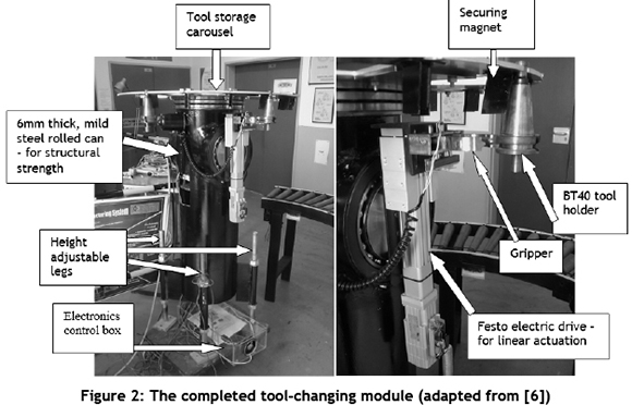
In the modular machine arena, the Mechatronics and Robotics Research Group (MR2G) of the University of KwaZulu-Natal has produced a 5-axis reconfigurable manufacturing machine prototype [3], along with a tool-changing unit that is able to interact with the machine tool [4]. The two units are shown in Figures 1 and 2 respectively.
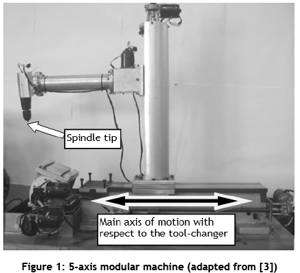
Tool-changing capabilities are normally designed as part of a manufacturing machine, and tool-changing facilities typically rely on the structure of the machine tool for stability. The developed tool-changer differed from this in that it was an independent module. It had to be structurally self-sufficient in order to allow the unit to service several machines. If it were designed to depend on structural support from the machine it was servicing, a different mechanical interface would be required for each machine it serviced. This would reduce its flexibility and increase downtime in the event of a re-configuration. With respect to the core values of reconfigurable systems, its integrability would be compromised. Integrability emphasises the ease with which different modules can be added to or taken from the manufacturing system [5].
Since the tool-changer was designed not to rely on a mechanical structure to acquire its position relative to the spindle, another method had to be used to determine its position. The unit also had to respond rapidly to any re-configurations of the system. A position-sensing system that allowed the tool-changer to adjust quickly to changes in the location of the spindle needed to be developed in order to maximise the advantages of reconfigurable systems.
A real-time 3D position-sensing system was developed using Nintendo Wii remotes. The system enabled the tool-changer consistently to detect the location of the spindle. This allowed the unit to calibrate itself automatically to variations in the position of the spindle, and to to adjust rapidly to any changes in configuration of the equipment. This paper presents the development of the positioning system, along with its testing and results.
2 THE NINTENDO WII POSITION-SENSING CONCEPT
In order to solve the problem of providing the tool-changer with an efficient and reliable method of determining the position of the spindle, a selection of commercially-available systems were researched. The evaluated commercial systems comprised measuring systems and visual recognition systems. The systems used technologies such as sonar, laser, and camera vision systems. The main drawback of the systems was their cost.
There were other reasons that contributed to the unsuitability of these systems for this project. The systems incorporated proprietary software that would hinder the integration of these devices into the broader reconfigurable control system. Several of the products provided more detail than was required for the tool-changer to interact successfully with the spindle. It was only necessary for the tool-changer to be able to establish the position of one feature; the spindle tip. The commercial systems were able to provide this, but some of the solutions were designed to provide a greater level of detail, detecting several features. The added functionality of the systems was part of what drove up their cost, and it was expensive to spend extra funds on unnecessary features.
One of the key ideas of modular reconfigurable systems is to provide designs that offer economical solutions to the unique requirements of these types of systems. It was imperative to find a solution that would allow the tool-changer to find the position of the spindle cheaply, so as not to overly increase the cost of the system. The technological advancements, along with the economic advantages of video gaming hardware, initiated the idea of researching these devices as a possible solution to the position determination requirements of the tool-changer.
The Nintendo Wii system was found to be a very economical option. It was able to provide the tool-changing unit with a real-time positioning system at a fraction of the cost of the commercially-available systems. The Wii system was able to deliver better positioning features at only 1 /50th of the price of some of the commercial systems. Another reason that the Wii system was used for this project was that it had been around for longer than some of the newer technologies. This meant that its technology was established, reliable, and well-tested. It also provided the advantage that use could be made of the second-hand market in order to reduce cost further. A final reason that the Wii system was chosen was that it offered wireless communication via Bluetooth. This capability would allow the Wii hardware to be attached to the tool-changer without the limitations imposed by power or communication cables.
The main component of the position-sensing system of the Wii gaming platform is the Wii remote or 'Wiimote'. The remote uses a 3-axis accelerometer along with an infrared (IR) camera to allow the console to 'read' the motions. A 'sensor bar' containing a 5-IR LED cluster at each end is mounted above or below the screen and is plugged into the console. As the remote is moved, the console picks up the motion of the camera in the remote relative to the stationary LEDs to determine the movement [7].
Although the Wii remote contains several sensors, the infrared camera was the primary one used in providing the tool-changer with its automatic calibration capability. The infrared camera is located on the front end of the Wii remote. The camera has an output resolution of 1024 x 768 pixels. It has a built-in image processing capability that allows it to track up to four infrared light sources simultaneously [8]. The camera tracks the sources at 100Hz, which allows it to provide a real-time tracking capability.
The Nintendo Wii offers a very versatile position-sensing system [9, 10], and several configurations could have been used. In the gaming arena the Nintendo system detects the movement of the Wii remotes relative to the stationary infrared 'blobs' on the sensor bar. In this research, the remotes remained fixed on the tool changer and detected the motion of an infrared LED mounted on the spindle of the machining tool. Two different configurations were used, which are presented next.
2.1 Dual remotes with a single LED
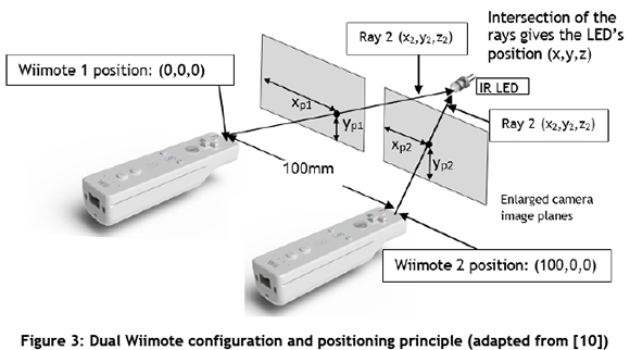
The first configuration that was used in determining the position of the spindle used two Wii remotes and a single infrared LED mounted at a suitable reference point on the spindle. This setup provides a stereoscopic 3D position system similar to that used by human eyes. Two Wii remotes were placed parallel to each other a known distance apart (100 mm). The infrared camera on each remote recorded the pixel x and y coordinates of the LED. The readings from the two cameras could then be combined to produce the 3D position of the LED relative to the cameras. The centre of the camera on the left was designated as the origin. The configuration is shown in Figure 3.
2.2 Single Wiimote with two LEDs
The next configuration used only one remote. Two infrared LEDs were used in order to enable the calculation of a position in three dimensions. The LEDs were mounted a fixed distance apart. The camera picked up the two pixel points (xp1, yp1) and (xp2, yp2). As the Wiimote moved away from the LEDs, the distance between the two points on the camera image plane decreased. This was a linear relationship if the effects of camera lens distortion were not considered. The positioning concept is shown in Figure 4.
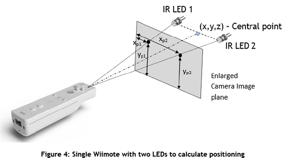
This configuration depended on the two LEDs being aligned to the camera image plane. If this was not the case, then accuracy would be compromised [11]. It should be noted that this system did not give the position of either of the LEDs but rather, the position of the midpoint between them.
The advantage of this system was that, since only one remote was used, setup was simpler. One did not have to be concerned with making sure that the two remotes in the previous concept were perfectly aligned and the correct distance apart. Another advantage was that it was more economical: only one remote had to be purchased,.The mathematics to work out the 3D position was also not as complicated as in the previous case. A significant advantage of this system was that it could also be used to determine the angle of the LEDs. This setup was particularly useful to the tool-changer, as it could be used to provide the angle of the spindle, and therefore take advantage of the specific feature of the tool-changer, which allowed for the presentation of tools at angles other than the vertical.
3 INITIAL TESTING OF THE WII POSITIONING SYSTEM
Nintendo has not released the technical details of the Wii system or remote, but its popularity and innovativeness has resulted in the successful reverse-engineering of the hardware by several online communities [12, 13]. The open source community has developed several software applications that allow the Wii remote to interact with computers using any of the major operating systems [8].
For this research, a computer running Windows XP was used as the host computer. Communication with the PC was achieved through the use of the Bluetooth capability of the Wii remotes interacting with Microsoft Bluetooth Stack on the computer.
3.1 Initial testing setup
For the initial testing and verification stage of the implementation, a light-weight application programming interface called GlovePIE was used. The application is a Programmable Input Emulator, which allows non-typical input devices to emulate computer commands. The application allowed readings to be taken from the Wii remotes, calculations to be performed, and outputs to be generated within the program. Although GlovePIE provided a good initial testing tool, it did have some difficulty in connecting with more than one Wiimote simultaneously.
In order to verify the accuracy of the Wii positioning system, use was made of a FANUC M-10iA robot. The robot's built-in position-measuring system was used to confirm the accuracy of the results obtained from the Wii remote and computer setup. An LED circuit was mounted to the end-effector of the robot. The LED could then be moved to the extremities of the view of the camera to determine the field of vision of the Wii remote camera. The field of vision was an essential characteristic, needed to convert the pixel value readings from the camera to a position in 3D space.
Once the field of vision of the Wii remote cameras was confirmed, the robot manipulator could be moved around its working space to determine the accuracy of the Wii position-sensing system at various locations. Figure 5 shows the arrangement of the robot testing setup with the stereo Wiimote configuration.

4 IMPLEMENTION OF THE WII POSITIONING SYSTEM ON THE TOOL-CHANGER
Once it had been verified that the Wii system provided an accurate 3D position, it could be tested on the tool-changer. Figure 6 shows the mounting of the dual Wii remotes on the tool-changer, as well as the location of the LED circuit on the spindle.

In order for the Wii remotes to be integrated into the control system of the tool-changer, a more robust software solution had to be developed. GlovePIE provided a good starting point for the testing of the Wiimote system, but a more user-friendly interface was required to ensure a practical and usable positioning system.
4.1 GUI development
The GUI was developed using Microsoft Visual Studio with Visual C# 2010 Express as the chosen programming language. There were several reasons for this choice. Visual Studio Express is a freely-available Integrated Development Environment (IDE), thus reducing development costs. C# is designed for developing a graphical interface. Visual C# offers a user-friendly graphical development environment, as well as some of the programming power available to a C or C++ programmer. Another reason that Visual C# was chosen was that a language was required in which libraries for accessing Wiimotes and their functions had been written. Developers have written libraries for interfacing a PC and a Wiimote for several programming languages [15]. Although there were other options, C# offered a quicker learning-curve for the intended application.
The managed library developed by Brian Peek [16] was selected as the basis for reading data from the Wiimotes in the GUI. Version 1.7 of the WiimotLib was used. Aspects of the Wii Device Library v 1.2 [17] were also used in the GUI development.
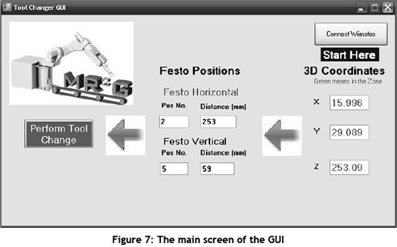
The developed GUI is shown in Figure 7. The 'Connect Wiimotes' button, which is located in the top right corner, was used to connect to any available Wii remotes. This opened up a Wii remote information panel for each of the available Wii remotes (Figure 8). Once the Wiimotes were connected, the GUI could output the 3D coordinates of the LED located on the spindle. These coordinates were mapped to the position settings of the FESTO drives to position the gripper in the required location. The 'Perform Tool Change' button then activated the motion of the tool-changer to implement the tool-change. The GUI indicated if the spindle was out of range or if there was no LED present.
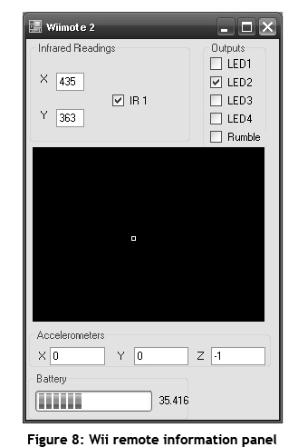
The Wii remote information panel shown in Figure 8 indicates the data read from each Wiimote. The black square represented the camera image plane of the Wiimote, and the small white square was a graphical representation of the position of the infrared LED. The 'Infrared Readings' section would output the pixel values of the LED location, and the check-box confirmed the presence of an IR source. Each Wii remote was able to sense up to four infrared sources.
The accelerometers were helpful in setting up the Wiimotes, since they gave an indication of the angle of the Wii remote. The values shown in Figure 8 (0, 0, -1) were the values given when the remote was horizontal, such as resting on a table. The battery level of the remote was shown as a percentage at the bottom of the panel.
The GUI provided a user-friendly method of implementing the Wii remote positioning system on the tool-changing unit.
5 EXPERIMENTAL RESULTS AND DISCUSSION
The initial testing setup was used to validate the concept of using Wii remotes to provide the tool-changer with an automatic position-sensing system. Once the concept had been verified, it was implemented on the tool-changing unit in two ways:
1. The stereo Wiimote configuration using one LED; and
2. The single Wiimote and dual LED setup.
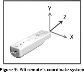
The coordinate system used in the testing is shown in Figure 9.
5.1 Initial testing of the stereo Wiimote concept
As described earlier in Section 3.1, a FANUC robot was used to validate the accuracy of the Wiimote positioning system. More than 200 readings were taken during the test. Previous research [7, 11] indicated that the stereo Wiimote system would only be accurate to 20 mm or 25 mm. The results recorded in this research established that the Wiimote system could perform more accurately. Table 1 shows the error distribution achieved over the entire range of readings. Readings were taken at various locations on the x-y plane between distances of 130 mm to 785 mm along the z-axis. Each axis is presented in Table 1, as well as the absolute distance error, which is the 3D distance between the target point and the Wii measurement.
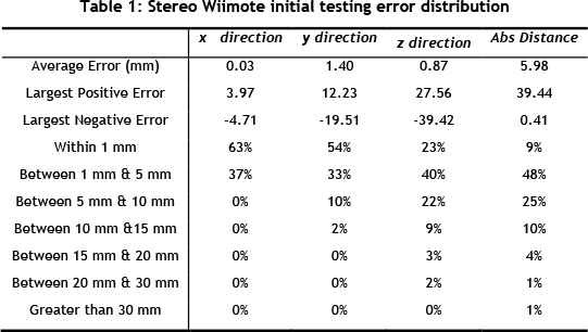
Due to the tapered design of the BT-40 tool, holder errors of 10 mm or 15 mm could be tolerated. It can be seen from Table 1 that over 90 per cent of the results had an absolute distance error of less than 15mm, and over 80 per cent fell within 10mm of the target.
For the tool-changing unit, the main region of interest would be between 200 mm and 400 mm from the Wiimotes. It was in this region that some good results were achieved, with 75 per cent of the absolute distance errors being under 5 mm, and 96 per cent of the results in this zone falling within 10 mm of the target point. These results were quite convincing, especially since the Wii remotes had only been aligned manually with a ruler.
An increase in errors occurred with greater distances from the Wii remotes. This was to be expected, as the errors would be compounded as the LED moved further away from the remotes. In the zone between 500 mm to 750 mm from the Wiimotes, the performance of the system reduced significantly. In this zone only 53 per cent of the errors were within 10 mm.
Analysing the results per axis shows that the x(horizontal)-direction proved to be the most accurate.
5.2 Tests on the tool-changing unit
The successful initial testing of the Wii remote positioning system allowed testing to be conducted using the Wii remotes on the tool-changer. The results of the two configurations used on the unit are discussed below.
5.2.1 The stereo Wiimote configuration
The stereo Wiimote configuration setup (shown in Figure 6) used two Wiimotes and one LED. Although the reconfigurable axis (see Figure 1) had a range of 400 mm, the Festo arm on the tool-changer could only reach out to 140 mm. The first set of tests on the tool-changing unit was conducted out to 140 mm along the machine axis. The differences between the Wii system and machine axis values were noted. Figure 10 summarises the results graphically.
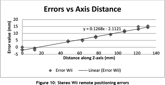
The linear trend in the increase of the Wii error, as the distance along the z-axis increases, is evident from Figure 10. The offset between the Wii position and the axis starting-point was 216 mm; therefore at the 131.5 mm limit of the Festo actuator, the Wiimotes gave a reading of 362 mm. The maximum Wii error of 14 mm at the end-point compared favourably with the results achieved in the previous tests.
Since the Wii error showed a linear progression, the software could easily be programmed to account for this increase in error. This adjustment would enable the Wii positioning system to deliver more accurate results.
It should also be noted that the alignment of the Wiimotes could be improved. As shown in Figure 6, the Wiimotes were placed in plastic holders. Although these holders enabled easy access to the Wiimotes, they did allow for some play in the remote position. The built-in accelerometers were used to aid in the setup, but they did not always detect the physical error of the Wiimotes. The parallel alignment of the remotes was again done manually with rulers. The location of the remotes above the carousel made it a little more difficult to perform this alignment. A more rigid mounting for the Wiimotes could improve accuracy.
5.2.2 Single Wiimote configuration
In the single Wiimote setup, a single Wii remote was mounted above the carousel, and a second LED was added to the circuit board mounted on the spindle.
For this configuration, tests were carried out in the region where a tool-change was possible. This was a narrow zone extending from where the gripper arm could clear the carousel and deliver a tool, to the limit of its extension: from 252 mm to 294 mm of the Festo arm extension, and 83.5 mm to 125.5 mm along the machine axis.
The spindle was located at several positions along the z-axis, and moved vertically up and down to test the variation along the y-axis. At each point the Festo arms were manoeuvred such that the BT-40 tool-holder would touch the tip of the spindle. The Festo coordinates, along with manual measurements taken on the machine axes, verified the Wiimote readings.
Table 2 shows the error distribution for the various axes of the Wiimote, along with the absolute distance error. The results show that the maximum error was just over 10 mm, and 95 per cent of the results along the tested machine axis were within 10 mm. These figures verify that the single Wiimote system provided a very acceptable solution for the tool-changer to make effective tool changes.
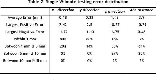
Comparing the single Wiimote system with the stereo one, it was observed that the single system provided more accurate results in the tool-changing zone. In the single Wiimote system, the greatest error along the axis in this zone was just over 10 mm, whereas in the stereo system the maximum error was almost 15 mm. The single Wiimote system was also significantly easier to set up, and provided the added advantage of giving the angle of the spindle.
6 CONCLUSION
Modular machines have unique requirements due to their modular structure. This paper presented a novel position-sensing system for a tool-changing unit within the modular-machine paradigm. Nintendo Wii remotes were used to provide the foundation of the positioning system.
Two configurations of the Wiimote system were tested. The first configuration involved using two Wiimotes in a stereo vision arrangement. A single IR LED was used as the reference point on the spindle of the test machine. The second configuration used a single Wii remote and two reference LEDs. This configuration was cheaper and simpler to set up than the stereo Wiimote one. It also provided the extra feature of being able to sense the angle of the spindle.
Both configurations were found to offer successful positioning systems for the tool-changing unit, with 95 per cent of the measurement errors being less than 10 mm in the tool changing zone. The configurations were both manually-aligned, and with this rudimentary setup the single Wiimote system was slightly more accurate. A more rigid setup procedure would be likely to produce even better results.
Using the Wiimote system, the unit was able to calibrate itself automatically with respect to the spindle position. It was able to determine the position of the spindle at all times, and adjust the parameters of its motion actuators when a tool change was required. The developed GUI provided a user-friendly environment for the positioning system to interact with the spindle. It provided feedback about whether the tool-changer was within the 'tool-changing zone', and automatically selected the required Festo actuator parameters.
The Wiimote system also proved to be extremely economical compared with other positioning systems, and it offered capabilities that the other systems could not.
REFERENCES
[1] Koren, Y., Heisel, U., Jovane, F., Moriwaki, T., Pritschow, G., Ulsoy, G. & van Brussel, H. 1999. Reconfigurable manufacturing systems. Annals of the CIRP, 48(2), pp. 527-540. [ Links ]
[2] Padayachee, J., Masekamela, I., Bright, G., Tlale, N.S. & Kumile, C.M. 2008. Modular reconfigurable machines incorporating modular open architecture control. 15th International Conference on Mechatronics and Machine Vision in Practice. Auckland, New Zealand, pp. 127132. [ Links ]
[3] Padayachee, J. 2010. Development of a modular reconfigurable machine for reconfigurable manufacturing systems. Masters thesis, UKZN internal publication: Durban, South Africa. [ Links ]
[4] Collins, J.E.T. & Bright, G. 2011. Automatic tool-changing within the reconfigurable manufacturing systems paradigm. South African Journal of Industrial Engineering, 22(2), pp. 6879. [ Links ]
[5] Katz, R. 2005. Design principles of reconfigurable machines. International Journal of Advanced Manufacturing Technology, 34(5), pp. 430-439. [ Links ]
[6] Collins, J. & Bright, G. 2010. A tool changing unit for modular reconfigurable manufacturing systems. 25th ISPE International Conference on CAD/CAM, Robotics and Factories of the Future. [ Links ]
[7] Wronski, M. 2008. Design and Implementation of a Hand Tracking Interface using the Nintendo Wii Remote. PhD dissertation, Department of Electrical Engineering, University of Cape Town. [ Links ]
[8] Lee, J.C. 2008. Hacking the Nintendo Wii remote. IEEE Pervasive Computing, 7(3), pp. 39-45. [ Links ]
[9] Nintendo Patent Application US 2007/0211027, 2007. Image processing apparatus and storage medium storing image processing program. Figures 16, 17 and p.10-11, Figures 20-23. [ Links ]
[10] Nintendo Patent Application, US 2007/0211026, 2007. Coordinate calculating apparatus and coordinate calculating program. Figure 16. [ Links ]
[11] Petric, T., Gams, A., Ude, A., & Zlajpah, L. 2010. Real-time 3D marker tracking with a WIIMOTE stereo vision system: Application to robotic throwing. Robotics in Alpe-Adria-Danube Region (RAAD), 2010 IEEE 19th International Workshop, pp. 357-362. [ Links ]
[12] Wii Homebrew. Available from: http://en.wikipedia.org/wiki/Wii_homebrew. Accessed on 1 May 2012. [ Links ]
[13] Wii Reverse Engineered. Available from: http://www.wiire.org/Main_Page. Accessed on 1 May 2012. [ Links ]
[14] Collins, J. & Bright, G. 2011. Automatic calibration of a tool-changing unit for reconfigurable manufacturing systems (RMS) using Nintendo Wii remotes. 26th ISPE International Conference on CAD/CAM, Robotics and Factories of the Future, Malaysia. [ Links ]
[15] Wiimote Libraries. Available from: http://sites.google.com/site/crayon3d/Home/wiimote- libraries. Accessed on 3 July 2012 [ Links ]
[16] Managed Library for Nintendo's Wiimote. Available from: http://channel9.msdn.com/coding4fun/articles/Managed-Library-for-Nintendos-Wiimote. Accessed on 3 July 2012. [ Links ]
[17] Wii Device Library. Available from: http://wiibrew.org/wiki/Wii_Device_Library. Accessed on 3 July 2012. [ Links ]
[18] Collins, J. 2012. Automatic calibration of a tool-changing unit for modular reconfigurable machines. Masters thesis, UKZN internal publication: Durban, South Africa. [ Links ]
* Corresponding author

