


Services on Demand
Article
 English (pdf)
 Article in xml format
 Article references
Indicators

Related links
-
 Cited by Google
 -
 Similars in Google
Share

 Permalink
South African Journal of Industrial Engineering
On-line version ISSN 2224-7890
Print version ISSN 1012-277X
S. Afr. J. Ind. Eng. vol.25 n.1 Pretoria Jan. 2014
GENERAL ARTICLES
Direct slicing approach for the production of perfused components by laser beam melting#
J.T. SehrtI, *; A. MarthaII; G. WittIII
IManufacturing Technology Department of Mechanical and Process Engineering Faculty of Engineering, University of Duisburg-Essen, Germany. jan.sehrt@uni-due.de
IIComputer Aided Engineering Department of Mechanical and Process Engineering Faculty of Engineering, University of Duisburg-Essen, Germany
IIIManufacturing Technology Department of Mechanical and Process Engineering Faculty of Engineering, University of Duisburg-Essen, Germany
ABSTRACT
In this paper, laser beam melting technology is applied to the manufacture of defined porous metal structures using the exposure strategies of the machine manufacturer. It turns out that specific filter characteristics such as density, permeability, pore size, porosity, and shear strength are comparable to conventionally-made porosities [1]. To overcome some restrictions imposed by the default settings of the machine manufacturer, and to manufacture ultra-lightweight products, our own investigations - such as direct slicing -lead to an alternative exposure strategy for the laser. Here unique exposure lines, with their corresponding start and end points, are individually designed according to their practical needs. Even though this procedure is very complex and time-consuming, it leads to new possibilities for the perfusion of liquid or gaseous fluids that run through metal walls.
In summary, the adjustment of the functional porosity of laser beam melted parts made of metal material is the focus of this investigation; and with it, the variation and determination of the proper process parameters is essential. With the easily adjustable porosities and pore sizes that are investigated, combined with the geometric freedom of laser beam melting, very complex elements can be integrated into one part; and this also leads to new fields of application.
OPSOMMING
Laserstraal smelttegnologie word toegepas op die vervaardiging van gedefinieerde poreuse metaalstrukture deur die gebruik van die blootstellingstrategieë van die toerustingvervaardiger. Die blyk dat spesifieke filtereienskappe soos digtheid, deurlaatbaarheid, poreusheid en skuifsterkte vergelykbaar is met konvensioneel vervaardigde poreushede. Om sommige beperkings as gevolg van die vervaardiger se verstekverstellings te oorkom en om ultraligte produkte te vervaardig is 'n alternatiewe blootstellingstrategie vir die laser ontwikkel. Unieke blootstellinglyne, met hulle ooreenstemmende begin- en eindpunte, is individueel ontwerp volgens hulle praktiese behoeftes. Al is hierdie prosedure ingewikkeld en tydrowend, lei dit tot nuwe moontlikhede vir die perfusie van vloeistof of gasagtige vloeiers wat deur metaalwande vloei.
Opsommend, die fokus van die ondersoek is die verstelling van die funksionele porositeit van laserstraal gesmelte metaal onderdele, en saam met dit, is die variasie en bepaling van die gepaste proses parameters noodsaaklik. Met die maklik verstelbare porositeit wat hier ondersoek word, tesame met die geometriese vryheid van laserstraal smelting, kan komplekse elemente in een onderdeel geïntegreer word, en dit gee aanleiding tot nuwe toepassings.
1 INTRODUCTION
With respect to the development of the market, there are some opportunities that can help to meet tomorrow's market demands. An opportunity is always created by seeking innovative and future-related ideas. However, sometimes these kinds of ideas cannot be implemented due to the lack of knowledge about the designing or manufacturing processes. In this case, additive manufacturing (AM) technologies such as laser beam melting may help - not least because they are becoming more and more important [2]. In general, AM differs from conventional technologies because it additively joins material to a physical part in layers instead of removing or forming material. For the manufacturing of metal parts with defined functional porosities, the manifold methods of powder metallurgy are usually used today [3]. However, some disadvantages of this method include the inefficiency of individual production owing to the high cost of pressing tools; the restrictions associated with undercuts; and the fairly high shrinkage in the sintering process [4]. This opens up an opportunity for AM processes. Here the characteristic additive build-up of laser beam melting provides the opportunity to manufacture porous and defined structures at specific areas in a single part. Furthermore, the process parameters are adjusted fully to combine dense areas and porous areas in a single part, depending on their needs, without any joining process afterwards. In addition, metal filters with very complex free-formed surfaces and inner geometries can be made. This again can be used for filter or cooling elements or for complex lightweight parts that cannot otherwise be processed for this purpose. In this paper, feasibility studies of producing defined porous metal structures using the laser beam melting technology are undertaken.
2 SPECIFIC OBJECTIVES
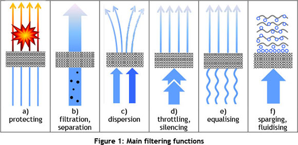
The focus of this investigation is to illustrate the new development and application potential of AM. One main objective is to investigate and develop specific scan strategies for the laser that can be applied in manufacturing open porosities. Open porosities are characterised by cavities and holes that are interconnected with each other and with their environment. These porosities can then be used for the perfusion of liquid or gaseous fluids, which is why they are often used as filter elements. The main filtering functions can be seen in Figure 1 [3][4]:
In this paper, the adjustment of the functional porosity of laser beam melted parts made of different materials such as stainless steel GP 1 and Hastelloy X is a focus of this investigation; and so the variation and determination of the preferred process parameters is essential. Another focus is the development of an approach for the direct slicing (DS) of CAD surface models in order to manufacture ultra-lightweight structures and alternative filter elements that cannot be processed in any other way.
3 BASICS ON POROUS STRUCTURES VIA LASER BEAM MELTING
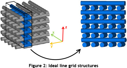
To manufacture porous structures via laser beam melting, different strategies can be considered. One possibility is the 3D design of porosities with a defined geometry, followed by the laser beam melting process itself. This is the common strategy for regular parts today. Nevertheless, for filter applications this strategy cannot be used because the pores inside are usually too big in this case. Another possibility for manufacturing porous structures is known from powder metallurgy, with its conventional sintering among individual particles (sinter neck formation). Using the laser beam melting technology, these structures are very difficult to manufacture, due to different particle sizes, the particle size distribution, and the bulk density of the base metal powder. In addition, the open porosity cannot be ensured. The investigated strategy in this work is a combination of a defined geometry and specific process parameters (cf. Figure 2). In this case, individual hatch lines (weld beads) in one plane do not touch one another laterally. Ideally, the weld beads only touch in height (z-direction), and in between very small and regularly-distributed holes remain in the system. However, in practice it is not possible to manufacture these ideal line grid structures. Due to the lack of heat dissipation to the underlying layer, the melt pool of each weld beads grows in height until it touches the one above it. Nevertheless, small holes remain in these areas through adjusting the process parameters. Generating the individual hatch lines is indeed defined; but the exact pore size and the pore size distribution are statistical.
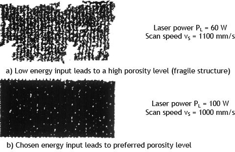
The interaction between the laser beam and the powder bed is dependent on various influencing parameters such as the laser power, the hatch distance, the layer thickness, and the scan speed [5]. For this investigation the layer thickness is set to 20 urn, which also corresponds to the standard layer thickness of the material. Since one single weld bead of stainless steel (GP 1) material is approximately 150 µm in width, the hatch distance is initially set to 300 µm in order to achieve equal spaces between the grid structures. For the investigation of the last two parameters, laser power and scan speed, a regular wall structure must be found with many small and regularly-distributed holes for the air or gas to perfuse. As a test for the first investigations, one single wall of the ideal line grid structures is used (cf. Figure 2). Because of the alternating xy-scan direction of the laser and the selected hatch distance, only one single weld bead is molten in the x-direction, whereas the y-direction shows about 30 short weld beads. In a matrix trial, the laser power is increased incrementally between 60 and 195 W in 20 W-intervals, while the scan speeds are varied between 500 and 1200 mm/s in 100 mm/s-intervals. After being separated from the building platform, all single walls are investigated. The lateral view of each single wall enables one to visualise the number, size, and distribution of the resulting holes. For that reason, single walls with only a few or with no holes are not considered. Here the energy input into the powder bed is too high for the manufacturing of porous walls, or even too high to manufacture parts at all (Figure 3c). Also, test walls with large or irregularly-distributed holes are not considered, due to their instability. Here the energy input of the laser into the powder bed is too low (Figure 3a). However, the best result - many small holes evenly distributed - can be achieved at a laser power of 100 W and a scan speed of 1000 mm/s. These parameters are selected for further investigation.
In order to change the porosity afterwards, the hatch distance is varied between 300 and 150 µm.
5 RESULTS AND DISCUSSIONS: SPECIFIC FILTER CHARACTERISTICS
Now the process parameters are validated by test procedures that are used to examine specific filter characteristics according to existing standards.
5.1 Specific permeability according to DIN EN ISO 4022
The DIN EN ISO 4022 [6] describes the determination of the fluid permeability of sintered metal materials made by conventional methods. However, the specific permeability is expressed as a friction-dependent permeability coefficient a (laminar flow) and an inertia-dependent permeability coefficient ß (turbulent flow). These two coefficients need to be calculated. The following equation shows the relation between all variables being used for this purpose.
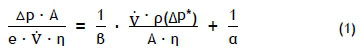
with α = viscosity coefficient; β = inertia coefficient;  = flow rate; e = filter thickness; η = dynamic viscosity air; A = filter surface; Δρ = revised pressure drop at the filter; Δρ* = differential pressure; and ρ(Δρ*) = fluid density dependent on differential pressure.
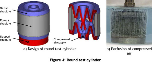
In order to determine the specific permeability, the round test cylinder below has been designed (cf. Figure 4a) and tested (cf. Figure 4b). The porous structure of the hollow test cylinder has an outer diameter of 30 mm, a height of 20 mm, and a thickness of 3 mm. It is intended that the compressed air runs through the inner geometry of the test cylinder, and then laterally through the porous structure of the cylinder. The porous structure of the hollow round test cylinder is laser beam melted with the four different hatch distances described above. Each cylinder is manufactured three times in order to ensure the results statistically. The perfusion of compressed air running through the porous structure can be seen in Figure 4b.
The calculated values for a and β in each group are shown in Table 1. The results for a are very similar to conventionally-manufactured metal filters. The negative values of β are striking. No value of conventionally-sintered metal filters is negative here. This difference can be explained by the fact that the pressure drop increases disproportionally to the flow rate at conventionally sintered filters. In contrast with this, the pressure drop of laser beam melted filters is not disproportional; on the contrary, the flow rates increase slightly disproportional to the pressure drop. The dynamic (turbulent) portion of laser beam melted filters is smaller compared with conventional sintered filters.
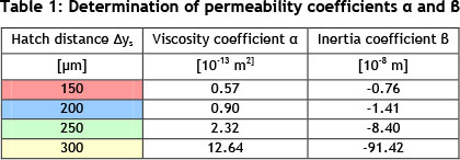
Despite these differences, the individual values of the flow rates and the pressure drops of laser beam melted filters are comparable with those that are conventionally manufactured. In addition, it can be expected that a further increase of the flow rates (higher speeds) lead to increased inertia effects of the particles, which counteract the flow direction.
5.2 Pore size according to DIN ISO 4003
According to DIN ISO 4003 [7], the so-called 'bubble-point' test is used to determine the size of the apparently largest pore of conventionally-sintered filters. Here the round test cylinder is immersed in isopropyl, which is characterised by low surface tension. This guarantees the saturation of all open porosities of the test cylinder. Now slowly increased compressed air is applied to the test specimen, and it presses the liquid out of the pores until the first bubble appears at the surface. According to DIN ISO 4003, the applied pressure at this point corresponds with the size of the capillary tension of the test liquid. Assuming a perfect circular pore shape, the apparently largest pore can then be calculated according to the following equation:

with d* = apparent pore diameter, y = surface tension isopropyl and Ap* = pressure drop at filter.
The results of this investigation can be seen in Figure 5. According to the graph, the desired pore diameters can be adjusted by varying the hatch distance.
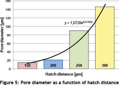
Compared with conventionally-made filters, here too the apparent pore diameter belongs to a circular pore whose circumference equals that of the real irregular-shaped pore. The real shape of the pores retains particles in the filter that are even smaller than the apparent pore diameter. For this reason, empirical values are given in DIN ISO 4003 that can be multiplied by the apparent pore diameter to get a hint of the smallest particle that actually remains in the filter element.
5.3 Porosity
The main feature of filter elements is their porosity, which significantly determines all the properties of a porous structure. Thus the porosity influences the mechanical properties of a part, the soaking grade (oil), the machinability, and the permeability for fluids [3][8]. Simply described, the porosity is the ratio of cavities (pore volume) to the total volume of a part. A simple method to determine the overall porosity of a part is the calculation of the ratio of the porous density to the theoretical density of the solid material (cf. Equation 3).
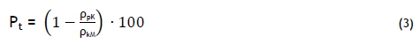
with Pt = total porosity; ρpK = density of porous part; and ρkM= density of solid material. For this investigation, porous cubes with an edge length of 15 mm serve as test specimens (cf. Figure 6 a). These cubes are laser beam melted, using the same parameters as for the porous structures described above.
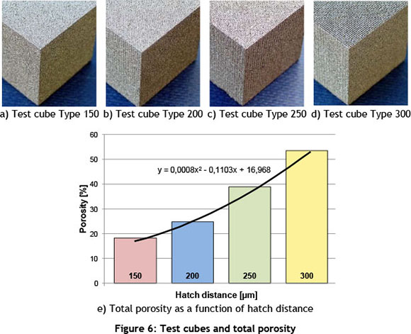
After being investigated, the following porosities can be calculated for the different parameters (cf. Figure 6b). As expected, the porosity increases with the hatch distance, from 17.2 % (hatch distance 150 µm) to 51.7 % (hatch distance 300 µm).
In addition, the shear strength according to DIN 30911 part 6 [9] has been investigated. Here the strength values of laser beam melted porous structures with 162 - 427 N/mm2 are far above the values of conventional sintered stainless steels (70 - 190 N/mm2).
6 DIRECT SLICING OF SURFACE MODELS IN COMMERCIAL CAD SYSTEMS
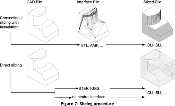
Since 3D Systems developed the STL (Surface Tessellation Language) data format in 1987, it has come to be the de facto standard for the data exchange and geometry representation in AM processes. Even though the requirements for AM interface formats are constantly being raised, there is no significant improvement in the STL data format [10, 11]. In addition, the algorithms for the conversion of CAD data into STL files still do not deliver high quality. Depending on the CAD system used, conversion errors and syntactic representation errors such as gaps, overlapping triangles, and incorrect orientation of normal vectors habitually occur [11, 12]. The disadvantages of the STL format have led to several attempts to improve it. For example, Wu and Cheung [13] presented an enhanced STL format that is able to store additional information with improved accuracy. In 2012 the ASTM specified the AMF format (Additive Manufacturing File Format). This XML-based format is an open standard for AM, and can store additional information such as colours, materials, and constellations [14]. However, these improved formats still have to convert the native CAD data before it can be processed. Subsequently these files are sliced. This complex procedure of data preparation is accepted as the working solution for most AM applications. However, as soon as it comes to highly specialised products with freeform surfaces, these file formats limit the geometrical design of AM parts. STL files always need so-called 'waterproof' volume models. Surface models cannot be processed. To overcome current restraints on data preparation [10], an approach for the direct slicing (DS) of CAD surface models is developed here. The Ds technique is able to process the native CAD data (see e.g. [15-18]) or neutral formats such as STEP or IGES (see e.g. [19]) which represent the original geometry (cf. Figure 7). Since direct slicing offers many opportunities without the tessellation of the 3D geometry, several DS procedures have been examined. Pendey, Reddy and Dhande reviewed various techniques in 2003 [20].
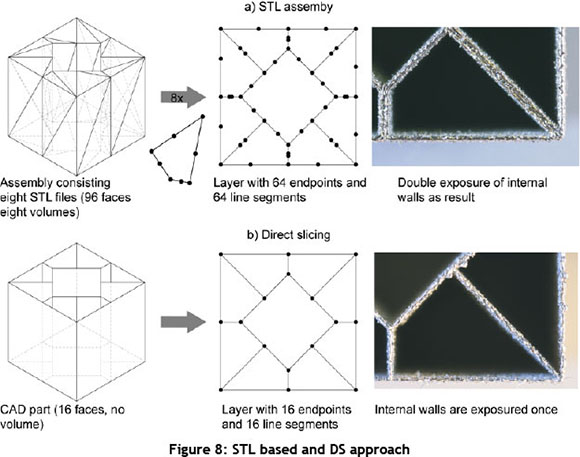
In this paper, the main reason for the DS approach is the limitation of the existing data preparation - and with it the limitation of the laser's desired scan strategy. The desired geometry for filter elements or turbo machinery parts cannot be tessellated for the STL export, because the geometry is represented as surfaces. However, increasing accuracy and part quality are good reasons to undertake these investigations. Nevertheless, one chosen geometry is manufactured conventionally by assembling several STL files and via the investigated DS approach (cf. Figure 8), explained below.
The main goal of the CAD-based DS approach is a graphical user interface (GUI) supported CAD application that transfers the requested AM functionalities to the CAD user. The application is integrated with the CAD system by the use of provided API functions. After the user has defined the build direction, the DS procedure directly generates the slice data as a CLI file. Additional file formats could also be used; but CLI files are proven to be stable for subsequent pre-process steps.
With DS, the geometry is sliced in the CAD system, and the necessary polygons are only generated in each layer. In this step, the number of necessary points in each layer can also be reduced, because straight lines only require one start- and endpoint instead of mid-line points in the STL-file. Thus the number of points in one layer is reduced, and they can be used to create more accurate polygons of curved segments. However, the CAD user has first to set the definition or the part orientation in the CAD environment. Today the machine operator usually applies this important step during work preparation. This knowledge must, therefore, be provided to the CAD user. Knowledge-based engineering (KBE) strategies deliver solutions to this problem. State-of-the-art pre-process software delivers good results for AM based on STL files. Useful functionalities of these products must be integrated into CAD systems, when the user should accept the DS approach. Feature-based support generation in the CAD environment is another possible extension.
7 DIRECT SLICING FOR FILTER APPLICATIONS
Here the new DS approach is applied to the manufacturing of porous structures such as filter elements. One of the biggest advantages here is the freedom of the design of each scan line. In addition, thinner and even more complex walls can be manufactured. In Figure 9 one 'old' lateral view of a single wall structure made of stainless steel (cf. Figure 9a) is compared with two 'new' lateral views of a single wall made of Hastelloy X, a high-temperature-resistant metal material usually used for parts and products that are exposed to heat (gas turbines, ovens etc.).
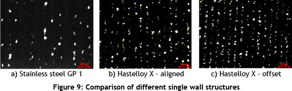
As Figure 9 shows, the distribution of pores inside the single wall structure is even better in the middle and on the right-hand side than on the left. In the middle and right-hand side pictures the DS approach is applied, which also corresponds to different exposure strategies of the laser. The left wall structure was utilised for the investigated filter elements (filter characteristics) described above. These structures are manufactured with the common xy-hatch exposure strategy of the machine manufacturer. Therefore the scan lines in the first layer are oriented in y direction, whereas the second layer represents scan lines in x direction. In this case all y-scan-lines are straight-aligned above each other. In the middle picture the scan directions are the same, but here the smallest possible laser diameter of the machine, which is usually only applied for support and contour structures, can be utilised. In contrast to this, the right wall structure is manufactured with three different layer exposure strategies than can only be done using the DS approach. In the first layer the scan lines are again oriented in y-direction. In the second layer the scan lines are oriented in x-direction. The difference now is in the third layer. Here the y-scan-lines have an offset of ¼ the distance, compared with the y-scan-lines of the first layer. This ensures a better and uniform heat transfer into the build platform and into the underlying layers, which in turn leads to uniform and regularly-distributed pores. Furthermore, the freedom of design, combined with the very thin wall structure, can be used to manufacture ultra-lightweight parts. However, tests still need to be carried out according to specific filter characteristics.
8 CONCLUSIONS
In this paper, investigations have been made into metal filters made via laser beam melting, with the adjustment of the functional porosity of laser beam melted parts made of stainless steel and Hastelloy X as their focus. It turns out that the process parameters can be adjusted in a way that combines fully dense areas and porous areas in individual parts, depending on what is needed, without any joining process afterwards. With the good adjustable porosities and pore sizes investigated here, combined with the geometric freedom of the technology, very complex filters can be integrated in parts. The results in section 5 also show that specific filter characteristics are comparable with conventionally-made sintered metal materials (cf. DIN 30910 part 2 [21]). According to this, the viscosity coefficients a of type 150 and type 200 are very similar when compared with the sintered stainless steel named Sint-AF 40-3 (cf. section 5.1). Also, the good adjustable pore sizes of the porous structure are a consequence of the geometrical freedom in laser beam melting (cf. section 5.2). In addition, the filter porosity of type 150 corresponds with the Sint-AF 40-3 structure, and the shear strengths of laser beam melted porous structures even show higher values compared with the values of sintered stainless steels (cf. section 5.3). These positive results, combined with the advantages of this layerwise technology, can lead to new fields of application in the future.
In summary, a number of advantages of the DS approach can be identified. The main reason for this approach is that the STL format is not able to export surface models. For this reason especially, this way of directly exporting slice data as CLI files was developed. First examinations of this approach were very successful. Beside this main reason for the DS approach, additional advantages can be identified. With DS, the number of generated process files is reduced because STL files are not required. This reduction simplifies the state-of-the-art PDM/PLM process, because fewer files and versions have to be handled. In addition, part quality can be enhanced. Furthermore, the native CAD geometry must not be tessellated before slicing; and even adaptive slicing can be considered and implemented in this approach in future.
REFERENCES
[1] Sehrt, J.T. & Witt, G. 2011. Manufacturing of defined porous metal structures using the beam melting technology, in Bártolo, P.J. (Hrsg.), Proceedings of the 5th International Conference on Advanced Research in Virtual and Rapid Prototyping, Leiria, Portugal, 2011, S. 639-644. [ Links ]
[2] Wohlers, T. 2011. Wohlers Report: Additive manufacturing and 3D printing state of the industry. Fort Collins, Col: Wohlers Associates. [ Links ]
[3] Schatt, W., Wieters, K.-P. & Kieback, B. 2007. Pulvermetallurgie - Technologien und Werkstoffe. Berlin Heidelberg : Springer-Verlag, 2007. [ Links ]
[4] Sehrt, J.T. 2010. Möglichkeiten und Grenzen bei der generativen Herstellung metallischer Bauteile durch das Strahlschmelzverfahren. Dissertation, Universität Duisburg-Essen. [ Links ]
[5] Meiners, W. 1999. Direktes Selektives Laser Sintern ein komponentiger metallischer Werkstoffe. Aachen: Shaker Verlag. [ Links ]
[6] DIN EN ISO 4022. 2006. Permeable sintered metal material - Determination of fluid permeability. [ Links ]
[7] DIN ISO 4003. 1990. Permeable sintered metal materials - Determination of bubble test pore size. [ Links ]
[8] Esper, F.J. 1996. Pulvermetallurgie - Das flexible und fortschrittliche Verfahren für wirtschaftliche und zuverlässige Bauteile. Renningen-Malmsheim: Expert-Verlag. [ Links ]
[9] DIN 30911 Part 6. 1990. Sintered metal materials - Sinter-testing procedures, Part 6: Determination of filter properties. [ Links ]
[10] Jurrens, K.K. 1999. Standards for the rapid prototyping industry. [ Links ]
[11] Danjou, S. & Köhler, P. 2008. Bridging the gap between CAD and rapid technologies. Exigency of Standardized Data Exchange. [ Links ]
[12] Szilvsi-Nagy, M. & Mátyási, G. 2003. Analysis of STL files. Mathematical and Computer Modelling 38.7, 945-960. [ Links ]
[13] Wu, T. & Cheung, E.H.M. 2006. Enhanced STL. The International Journal of Advanced Manufacturing Technology 29, no. 11-12. [ Links ]
[14] ASTM. Specification for Additive Manufacturing File Format (AMF). ASTM International: West Conshohocken, PA. [ Links ]
[15] Mohammad, B.A. & Hayasi, T. 2008. Machine path generation using direct slicing from design-by- feature solid model for rapid prototyping. Publisher? [ Links ]
[16] Jamieson, R. & Hacker, H. 1995. Direct slicing of CAD models for rapid prototyping. Publisher? [ Links ]
[17] Chen X., Wang C., Ye X., Xiao Y. & Huang, S. 2001. Direct slicing from PowerSHAPE models for rapid prototyping. Publisher? [ Links ]
[18] Sun, S.H., Chiang, H.W. & Lee, M.I. 2007. Adaptive direct slicing of a commercial CAD model for use in rapid prototyping. Publisher? [ Links ]
[19] Starly, B., Lau, A., Sun, W., Lau, W. & Bradbury, T. 2005. Direct slicing of STEP based NURBS models for layered manufacturing. Publisher? [ Links ]
[20] Pandey, P.M., Reddy, N.V. & Dhande, S.G. 2003. Slicing procedures in layered manufacturing: a review. Publisher? [ Links ]
[21] DIN 30910 Part 2. 1990. Sintered metal materials - Werkstoff-Leistungsblätter (WLB) Sint-material specifications - Part 2: Materials for filters. Publisher? [ Links ]
# This article is an extended version of an article presented at the 2012 RAPDASA conference
* Corresponding author

