


Servicios Personalizados
Articulo
 Inglés (pdf)
 Articulo en XML
 Referencias del artículo
Indicadores

Links relacionados
-
 Citado por Google
 -
 Similares en Google
Compartir

 Permalink
South African Journal of Industrial Engineering
versión On-line ISSN 2224-7890
versión impresa ISSN 1012-277X
S. Afr. J. Ind. Eng. vol.24 no.3 Pretoria nov. 2013
GENERAL ARTICLES
The design of reconfigurable assembly stations for high variety and mass customisation manufacturing
J. PadayacheeI, *; G. BrightII
IDiscipline of Mechanical Engineering. University of KwaZulu-Natal, South Africa.padayacheej@ukzn.ac.za
IIDiscipline of Mechanical Engineering. University of KwaZulu-Natal, South Africa.bright@ukzn.ac.za
ABSTRACT
The economical production of mass customised and high variety goods is a challenge facing modern manufacturers. This challenge is being addressed, in part, by the on-going development of technologies that facilitate the manufacturing of these goods. Existing technologies require either excessive inbuilt flexibility or frequent changes to the machine set up to provide the manufacturing functions required for the customisation process. This paper presents design principles for automated assembly stations within the scope of mass customisation. Design principles are presented that minimise the hardware and operating complexities of assembly stations, allowing stations to be easily automated for concurrent mixed model assembly with a First In First Out (FIFO) scheduling policy. A reconfigurable assembly station is developed to demonstrate how the proposed design methods simplify the creation and operation of an assembly station for a product family of flashlights.
OPSOMMING
Die ekonomiese vervaardiging van grootskaalse aangepaste en hoë verskeidenheid goedere is 'n uitdaging wat hedendaagse vervaardigers in die gesig staar. Die uitdaging word deels geadresseer deur die ontwikkel van tegnologieë wat die vervaardiging van hierdie goedere fasiliteer. Bestaande tegnologieë vereis egter uitgebreide ingeboude aanpasbaarheid of gereelde veranderinge aan die masjienopstelling, om die vervaardigingvermoë deur die aanpassings proses vereis, te verskaf. Hierdie artikel hou ontwerpbeginsels voor vir geoutomatiseerde monteerstasies binne die bestek van massa aanpasbaarheid. Die ontwerpbeginsels minimeer die hardeware- en bedryfkompleksiteit van monteerstasies. Hierdie benadering vergemaklik dit om stasies te outomatiseer vir gelyklopende gemengde model montering met 'n Eerste-In-Eerste-Uit (FIFO) skeduleringsbeleid. 'n Herkonfigureerbare monteerstasie is ontwikkel om te demonstreer hoe die voorgestelde ontwerpbeginsels die skep en bedryf van 'n monteerstasie vir 'n produk-familie van flitsligte vereenvoudig.
1 INTRODUCTION
Mass customisation manufacturing (MCM), a paradigm that emerged in the 1980s, relates to the production of customised goods in high volumes and at rates and prices comparable to mass produced items [1, 2]. Research performed by MacDuffie et al. [3] has demonstrated that an increase in product variety has a significantly negative impact on manufacturing system productivity. In order to satisfy the increasing demand for product variety and customisation, existing production systems must be improved [4]. Revisions to current manufacturing technologies are necessary, as simply adding highly flexible equipment or building high levels of functionality into manufacturing systems does not provide an economical solution.
Hu et al. [2] identified the importance of the product assembly stage in offering an economical solution to providing high product variety. Significant product diversification and customisation can be provided by the development of product modules with multiple variants that are assembled in different configurations [5]. The development of modular product families for mass customisation is discussed by Elgárd and Miller [6]. The number of assembly combinations increases factorially with an increase in module variants; this presents significant challenges in the design and operation of assembly systems [7]. Related challenges become more prevalent when there is a need to automate assembly processes in order to increase productivity.
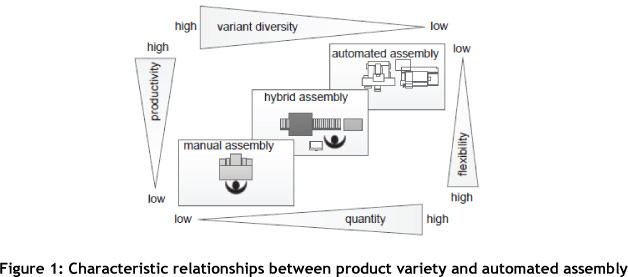
Gyulai et al. [8] presented the characteristic relationship exhibited between product variety and automated assembly using existing manufacturing technologies and techniques. The relationship illustrated in Figure 1 shows a reduction in product diversity as the level of automation increases. This is primarily due to a reduction in the flexibility of assembly processes as automation is added. The automation of an assembly process for MCM and high product variety is complicated by the necessity to provide multiple tools, fixtures, and machine programmes for different product variants. At a system level the design of the assembly station influences how product batches are scheduled. The trade-off is an increase in product tardiness in an effort to minimise how often the set-up of an assembly station is changed.
The aim of this research was to develop and test design principles for reconfigurable assembly stations that will simplify their automation and eliminate the necessity for set-up changes when used for MCM. Design principles were also formulated for assembly stations that promote a First In First Out (FIFO) work flow, thereby negating the tardiness and manufacturing control complexity introduced by batch scheduling.
The paper proceeds as follows: Section 2 reviews relevant literature on the design of reconfigurable assembly systems. Section 3 presents complexity models for mass customisation by assembly. Section 4 presents principles for the design of reconfigurable assembly stations for MCM. Section 5 presents a practical application of the proposed design principles through the construction and operation of a reconfigurable assembly station. Section 6 discusses matters arising in product design, and the feasibility of pellet-based assembly in RMS.
2 RECONFIGURABLE ASSEMBLY SYSTEMS
2.1 Definition and characteristics of reconfigurable assembly systems
The concepts of reconfigurable manufacturing systems (RMS) and reconfigurable assembly systems (RAS) were proposed by Koren et al. [9, 10] to facilitate the profitable production of high variety and customised goods. Koren and Shpitalni [10] defined a RAS as follows: "Reconfigurable assembly systems are those that can rapidly change their capacity (quantities assembled) and functionality (product type, within a product family) to adapt to market demand". Koren further stated that, in order to be reconfigurable, assembly systems should exhibit the following characteristics:
- Customisation: the design of assembly systems to produce a specific part family.
- Convertibility: the rapid conversion of assembly systems to produce a different part in the family.
- Scalability: the ability to adjust the throughput of a system quickly.
2.2 Modularity as a characteristic of RAS
Bi et al. [11] have emphasised modularity as an important characteristic of RAS technology. The ability to add, remove, or rearrange modular units such as tools, fixtures, and robotic manipulators enhances the capability of such a system to cater for product changes and variations. Modularity is also an enabler of customisation, convertibility, and scalability. Molfino et al. [12] defined four categories for modular reconfigurable assembly technologies:
- Process modules: machines used to perform assembly operations, such as welding machines and electric screwdrivers.
- Actuation modules: actuators used for material handling and positioning, such as pneumatic cylinders and electro-mechanical linear drives.
- Interfacing modules: clamps and grippers that come into direct contact with parts, providing the interface between actuation modules and parts.
- Control modules: electronic elements such as Programmable logic controller (PLC)s and data acquisition boxes that are integrated into a RAS when mechanical hardware is added to the system.
The relationship between customisable product modules and modular assembly technology must be considered as early as the product design phase, in order to reduce the complexity and cost of designing a RAS. Bi et al. [11] raise the concern that, although ample literature is available on product design for assembly (DFA), not much work has been done to relate product design decisions to reconfiguration requirements for assembly.
2.3 Reconfigurable fixtures for RAS
An important enabler for RAS is reconfigurable fixtures for work holding and accurate positioning of components during the assembly process. Sela et al. [13] developed a modular reconfigurable fixture system for thin-walled flexible objects. The modularity of the system enabled the physical reconfiguration of clamps and locators to provide adequate support to thin-walled objects during processing. Kong and Cegiarek [4, 14] developed an approach for rapid reconfigurable fixture deployment based on work space synthesis. The approach used fixture visibility analysis with the aim of reducing the calibration time after fixtures have been reconfigured. Izquierdo et al. [15] proposed a methodology for optimal fixture layout design in a reconfigurable assembly line, using a sequential quadratic programming approach. The method was applied to a case study on the assembly of automotive side frames for small, medium, and large vehicles.
2.4 Fixtureless assembly for RAS
Fixtureless assembly has been of interest in the development of RAS due to its advanced flexibility. A fixtureless reconfigurable spot welding system was designed by Dymond et al. [16] for the automated assembly of circuit breakers. The design used two robotic manipulation systems to secure and position components for welding. Bone and Capson [17] investigated the use of sensor-guided robots for fixtureless assembly of automotive components. The robots were equipped with programmable grippers for holing a wide range of components without tool changing. A 3D computer vision system was used to obtain the correct pose of parts prior to joining. This system also deployed two robots to complete the assembly operation.
2.5 Industrial robotics and robotic cells
Industrial robots have become popular in fixture-based and fixtureless reconfigurable assembly operations. The flexibility of a robot allows it to be used for part manipulation and the application of joining techniques such as welding. Asada and By [18] introduced the concept of automatically reconfigured fixturing by using a robot to relocate fixtures. The authors presented tools for kinematic analysis and fixture layout design. The use of the tools was demonstrated on the fixturing of an electric drill's outer plastic cover.
The flexible automation available in robots further enhances their ability to be used in high variety manufacturing. Makris et al. [19] presented a case study from the automotive industry, where Radio-frequency identification (RFID) infrastructure was integrated with robots for assembly in random mix manufacturing. The RFID infrastructure enabled part identification, which was used to reconfigure the assembly process via an RFID event-handling software module. For each part variant, a file was uploaded to the robot's controller with information enabling the robot to perform the relevant operations.
The ability rapidly to add or remove a robot from an assembly system has also been identified as a feature of reconfigurable assembly systems. Sugi et al. [20] and Maeda et al. [21] proposed the concept of an holonic robotic system for obtaining high levels of reconfigurability. The holonic management system enabled a robot to be quickly added to an assembly cell, resolving workspace allocation and preventing physical conflict between the robot and other devices in the cell. A robot could also be quickly removed by redistributing work to other robots in the system and updating workspace information.
Chen [22] identified the importance of 'plug and play' component-based technology for rapidly reconfigurable and robotic work cells. This is an application of modularity to smaller, elementary units of hardware that are used to add functionality to larger assembly equipment such as robots. Chen demonstrated this concept through the creation of modular building blocks for parallel robots. The building blocks consisted of modular actuators, joints, and links such as those illustrated in Figure 2.a. These modular building blocks could be arranged in varying numbers and configurations to create different robots, such as the 3-DOF and 6-DOF parallel robots shown in Figures 2.b and 2.c respectively. Modular and reconfigurable robots of this nature have the potential to be a significant technology for highly reconfigurable assembly systems.
2.6 Control of reconfigurable systems
The creation of RAS requires the development of control infrastructure and software that can enable the rapid reconfiguration of, addition to, or removal of hardware from a RAS. A significant component of the control challenge relates to the logical reconfiguration of control programs. Lejri and Tagina [23], Li et al. [24] and Zhang and Rodrigues [25] used Petri nets to model manufacturing processes. The authors demonstrated how Petri nets could be reconfigured to alter the sequential control of a process in conjunction with the physical reconfiguration of the system. Modular finite state machines (MFSM) were proposed by Endsley et al. [26] as a logic framework for the control of RMSs. The MSFM technique developed by Endsly et al. was used to develop a controller for the reconfigurable factory testbed (RFT) at the University of Michigan's Engineering Research Center. The identification of appropriate software techniques is also necessary for the successful implementation of the reconfigurable control logic provided by Petri nets and MFSM. Bruccoleri [27] developed a software framework for reconfigurable manufacturing cells. The research demonstrated how object orientated (OO) techniques facilitated the easy reconfiguration of the control software, while providing real-time process monitoring, network integration, and exception handling.
3 COMPLEXITY IN RAS
3.1 Product induced complexity
Product modularization and customisation through module assembly is a prominent technique in mass customisation [2, 7]. Increasing the module mix increases the complexity of assembly processes. Hu et al. [7] developed a station level complexity model for the assembly of customised products. The authors describe complexity as the average uncertainty in a process i, and used Shannon's entropy function to define it:

where pij is the occurrence probability of state j, j Є {1,2 ...Mi}, in assembly process i due to the assembly of customised modules associated with that state. An example of states in an assembly process is the tooling state - i.e. selection of a particular tool in a fastening process. C is a constant depending on the units of Shannon's entropy function; if the unit of complexity is bit, then log2 is used and C =1. For an assembly station p with K assembly processes (activities), the assembly complexity at that station is:

System level complexity and assembly supply chain complexity models are also presented by Hu et al. [7]. These models will not be presented here; however, the basis for these models is the station level model presented in equation (2). For product-induced complexity to be mitigated at a station and ultimately at a system level, the product must be designed with the following objectives: reduce the number of potential states for each assembly process i, and reduce the number of assembly activities K required. The design of a RAS must also be considered as early as the product design phase to obtain the most economical compromise between product diversification, product modularity, and ease of assembly. Wang et al. [28] proposed a similar viewpoint, stating that the product and the manufacturing system should be designed concurrently to mitigate complexity.
3.2 Complexity of RAS Technology
Feldmann and Slama [29] state that highly modular and reconfigurable systems display the greatest adaptability to assembly tasks. However, because of their complexity they require the greatest planning and effort to implement. Mechanical or hardware changes to a RAS usually necessitate additional changes to the electronic and software control systems. Advanced work cell controllers such as the one developed by Sugi et al. [20] and Maeda et al. [21] are required for rapid reconfiguration. The complexity of RAS will cause a manufacturer additional cost through the need for recalibration, troubleshooting and debugging activities on a system after reconfiguration, lost productivity due to time spent on reconfiguration, and the necessity to employ highly skilled technical staff. System reconfigurability is a tool to manage product variations; but if the complexity of a RAS is not adequately constrained, the solution becomes unprofitable.
4 DESIGN PRINCIPLES FOR ASSEMBLY STATIONS
4.1 Design objectives
Design principles are presented here for a single robotic assembly station. The design principles are specified to mitigate the following types of complexities:
1. Scheduling complexity: promote concurrent mixed model assembly and FIFO flow.
2. Load balancing complexity: eliminate positive and negative drift in assembly cycle times, which may create bottle necks or buffer starvation at other stations/cells.
3. Reconfiguration complexity: minimise the need to add or remove processes, actuators, and interface or control modules; avoid reconfigurations that require the station to be recalibrated.
4. Automation complexity: minimise the number of different control routines that the station will have to execute for different product variations.
4.2 Principles for the addition of flexibility and reconfigurability
The decision to add flexibility and reconfigurability to various subsystems of an assembly station will determine the complexity of designing and operating the station. In the context of a single assembly station and its subsystems, the following definitions of flexibility and reconfigurability are relevant:
Flexibility: refers to the ability of an assembly station to cater for product variety through dynamically adjustable mechanisms, such that the station can continue operation without a change to the setup of its subsystems.
Reconfigurability: refers to the ability of an assembly station to cater for product variety through the addition, removal, or rearrangement of process, actuation, interface, and control modules.
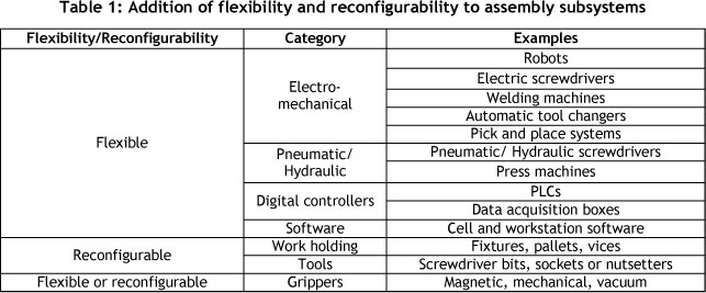
Table 1 provides a brief guide to where flexibility or reconfigurability should be added, based on the complexity of making changes to those modules or subsystems. The table was populated on the basis of the following rules for adding flexibility and reconfigurability to assembly station subsystems:
1. Reconfigurability should only be added to those subsystems that do not require the assembly station to be taken offline or recalibrated as a result of product variation. The assembly station should only be taken offline for reconfiguration at the end of a product's lifecycle, or when drastic revisions are made to the product.
2. Flexibility must be added to those subsystems to which reconfigurability cannot be added without requiring the station to be taken offline or recalibrated frequently.
4.3 The principle of pallet-based assembly
The potential for pallet-based assembly to be used in reconfigurable systems was highlighted by Heilala and Voho [30]. Traditionally, pallets have been used for work holding during transportation. However, in more advanced pallets, fixtures may be added to position the work piece accurately and firmly. Figure 3 illustrates an example from Ohashi [31] where fixtures were added to a pallet to clamp work on to the pallet for processing.
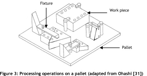
If fixtures are added to a pallet, the advantage is that the part or subassembly orientation is known when it enters the station. Knowing the orientation of components simplifies the automation of the assembly process by eliminating the need for additional sensors, robot vision, and software routines to determine the correct orientation. The addition of fixtures further enhances the ability of the pallet to be used on the assembly station. If a large component or a subassembly is appropriately fixed on a pallet, the pallet itself may be clamped on to the station. The accurate positioning of the pallet in the assembly station will then enable other components to be added, and the product can be constructed on the pallet, eliminating the need to transfer a larger component or subassembly to/from the pallet. Additional material handling complexity is also eliminated, as a system will have to handle a pallet with standard gripping points rather than with a variety of components.
4.4 The principle of transferred reconfigurability
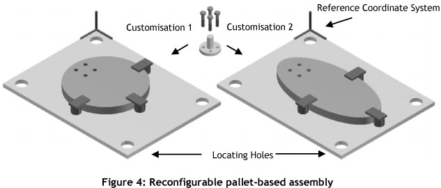
'The principle of transferred reconfigurability' in this context refers to the transfer of reconfiguration activities away from the assembly station to other entities in the manufacturing system. This principle is easily applied to work transportation pallets that are separate entities from the work station, yet could simplify assembly activities. In addition to the advantages presented in Section 4.3: if reconfigurability is transferred to the pallet and its fixtures, this can minimise variations in tool or gripper position points for customised products. Consider the example illustrated in Figure 4, where an additional part is to be bolted on to a customisable base. The fixing of the bases on to a pallet can be configured such that the bolt pattern is always spatially positioned at the same point relative to a coordinate system placed on the pallet. A robotic manipulator would therefore have to position the additional part at exactly the same spatial point, irrespective of the customisation of the base in each cycle. The pallet itself may have locating holes or pins, as illustrated in Figure 4, that assist with the accurate and repeatable positioning of it on the assembly station. Vallance et al. [32] have presented a methodology for the exact positioning of pallets in multi-station assembly using split-groove kinematic coupling.
4.5 Regulating and minimising assembly cycle times
The challenge in designing a reconfigurable assembly station is to maintain a constant assembly cycle time for concurrent mixed model assembly. The techniques of pallet-based assembly assist with minimising and maintaining a constant assembly cycle time in the following ways:
- material handling of pallet rather than of customised components that may require gripper changes;
- transferring reconfigurability to the pallet, and reconfiguring the pallet as a separate activity, offline from assembly activities;
- minimising variations in tool paths by manipulating pallet fixture configurations.
If the variation in assembly cycle time for various customised products is minimised, it is possible to use a constant timing mechanism as a driver for the activities on the assembly station. Such mechanisms may be either mechanical or electronic; examples include toothed timing belts, Geneva wheels, cam shafts, or the timers and counters available in PLCs and microcontrollers.
An additional strategy for minimising cycle times is to load components on to the station while assembly activities occur on other products. This will, to an extent, eliminate material handling time from the total assembly time.
5 PRACTICAL APPLICATION: AN ASSEMBLY STATION FOR FLASHLIGHTS
5.1 Assembling a part family of flash lights
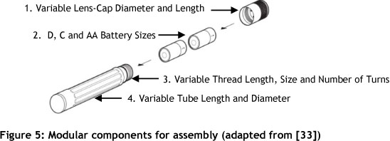
A robotic assembly station was constructed using the design principles and recommendations presented in Section 4. The station was developed to assemble a family of flashlights that consisted of three modules: the tube, the lens-cap, and the batteries. The customisations and modules for assembly are shown in Figure 5; mechanisms of flexibility and reconfigurability were added to the station for each of the four customisations shown in the figure.
5.2 Reconfigurable pallet design
The principle of pallet-based assembly presented in Section 4.3 was applied to the design of the station. This implied that the assembly of the entire flashlight took place on the pallet. The advantages of a known part orientation and minimisation of material handling complexity were derived from this. The pallet was used to support the variable length and diameter flashlight tube. The tube was the component to which other parts were added. The principle of reconfigurability transferred to the pallet, presented in Section 4.4, was used to cater for the variation in tube length and diameter. Reconfigurability was added to the height adjustable support shown in Figure 6.a, which was used to support the base of a flashlight tube. The sliding adjustment mechanism shown in Figure 6.b manipulated the height of the support, such that the threaded section of the tube was always at the same point in space for the fastening operation, irrespective of the length of the tube. Reconfigurability was also added to the pallet by creating a modular cap. The cap was used to clamp tubes of various diameters and cross-sectional profiles. The modularity of the cap allowed it to be interchanged with other caps as the cross-sectional profile of a tube varied. Figure 6.c shows various flashlight tubes fixed on to the reconfigurable pallets. The pallets were then stored in an on-station rotary buffer, designed specifically for pallet storage, providing a consistent and easy point of access for the robotic manipulator. An advantage of the pallet is illustrated in Figure 6.c, where the rotary buffer was designed to store a standard pallet rather than a variety of flashlight tubes.
5.3 Flexible and reconfigurable gripping
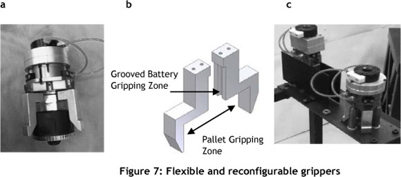
Flexibility and reconfigurability were added to the robotic gripping devices, according to the recommendation in Table 1. The three finger gripper illustrated in Figure 7.a was designed with the flexibility to hold all varieties of flashlight lens-caps. The two finger gripper, illustrated in Figure 7.b, was designed with the flexibility to grip pallets and all three varieties of batteries (D, C, and AA). To eliminate the need for three different grippers, the two finger gripper was designed with a pallet gripping zone and a grooved, battery gripping zone. This eliminated the cost of incorporating a third gripper, and reduced the assembly cycle time by eliminating one gripper change. The two and three finger grippers were connected to the robotic manipulator by a quick change pneumatic interface. The grippers were stored in a docking station, as illustrated in Figure 7.c; recalibration of the robot control system was therefore not necessary between gripper changes.
5.4 On-station buffering and cycle time regulation
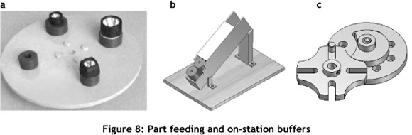
Three types of on-station buffers where added to the system. The purpose of adding on-station buffers was to allow parts to be loaded on to the station while other parts were being assembled by a robotic manipulator. This eliminated some of the component handling time from the total assembly cycle time. The pallet buffer is shown in Figure 7.c; the lens-cap buffer is shown in Figure 8.a. The lens-cap buffer was designed such that the centre of the cap is always at the same point in space for gripping. Three types of buffers were made available for each of the three sizes of batteries; an example of this type of buffer is shown in Figure 8.b.
The Geneva wheel mechanism shown in Figure 10.b was used to maintain a constant assembly cycle time on the station, according to the recommendation in Section 4.5. A Geneva wheel is used to convert a constant rotary motion from a driving motor into discrete incremental motion. The wheel was used to actuate the pallet and lens-cap rotary index buffers. All other activities in the station, including the activation of the robotic manipulator, were timed according to the rotation of the Geneva wheel. The timing of the wheel was regulated by a PID controller, and the complete assembly routine was executed for each 90o indexation of the wheel.
5.5 Flexible actuation
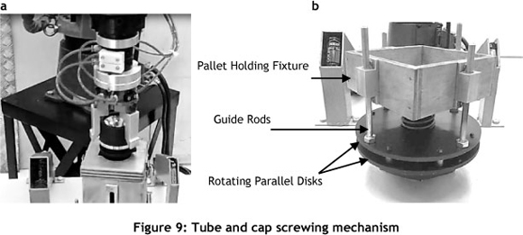
The assembly process began by picking up a pallet from the pallet buffer and placing it into the pallet holding fixture shown in Figure 9.b. A robotic arm loaded the flashlight tube with the correct batteries, and then picked a matching lens from the lens buffer. Since the reconfigurable pallet repeatedly positioned the thread of the tube at the same point in space, the robot would then place the lens at the same point in space in each cycle. This significantly simplified path planning for the robotic manipulator. Figure 9.a illustrates the robotic manipulator placing the lens at the point of thread engagement with the tube. Once the tube and lens-cap are at the point of thread engagement, a 12 V DC servo-motor begins to rotate the parallel discs shown in Figure 9.b, and the components are tightened.
The entire mechanism illustrated in Figure 9.b is the fastening/tightening mechanism. Because the thread size and number of threads were variable on the flashlights, either flexibility or reconfigurability was necessary in this mechanism. Based on the guidelines in Table 1, flexibility was added to this system, as it is an electromechanical system. Flexibility was added in two ways. The first was to suspend the pallet holding fixture above the rotating disks by a central spring and guide rods; this allowed the pallet holder to move vertically. This degree of freedom allowed the robotic manipulator to push the lens down on to the torch tube, compensating for any vertical misalignment of tube and lens thread due to product variation.
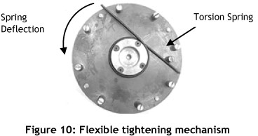
Flexibility was also necessary to allow for different torque settings and a variable number of turns for different flashlight assemblies. This flexibility was added through the inclusion of the parallel disks shown in Figure 9.b. The disks rotate continuously and synchronously until all the threads of tube and lens-cap are engaged, irrespective of the number of threads. Once all the threads are engaged, any additional rotation of the lower disk will cause asynchronous rotation of the upper disk due to the activation of the torsion spring shown in Figure 10, which was placed between both disks. Thereafter the correct torque setting is obtained by the angular deflection of the spring. This angular deflection was measured using a HEDS-5540 optical encoder and controlled by an ATmega32L microcontroller.
5.6 Cycle time performance
The complete reconfigurable robotic assembly station is shown in Figure 11. The design guidelines presented in Section 4 allowed the station to perform a concurrent mixed model assembly of a variety of flashlights. The station did not have to be taken offline to be reconfigured, and no recalibration of the station was necessary for different product variants.
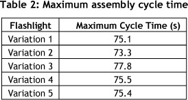
The technique of reconfigurable pallet-based assembly led to minimal variations in assembly cycle times. Table 2 presents the maximum cycle time for five different varieties of flashlight. The cycle time of the Geneva wheel was set to 80 seconds per 90o index to account for all varieties, and thus the cycle time of the station was constant at 80 seconds. The station was operated at a fraction of the speeds that the robotic manipulator and other actuators could manage for the purpose of laboratory testing; however, the tests do reveal that concurrent mixed model assembly and other previously listed benefits may be derived from the strategic application of reconfigurability and flexibility to various subsystems.
5.7 Analysing complexity
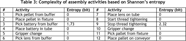
The complete assembly routine presented in Table 3 is listed in numerical sequence. This routine was applicable to all varieties of flashlights, and is completed in a cycle time of 80 seconds. Shannon's entropy, which is a measure of complexity calculated from equation (1), is listed for each activity with unit bit. The entropy for battery selection (activity 3) was calculated on the basis that all three types of batteries have an equal selection probability of 33.3%. Entropy for the gripper change (activities 5 and 10) was based on selection probability of 50% for the two grippers. The decision to stop the thread tightening (activity 9) was based on five different torque settings for five flashlight variants, each with an equal occurrence probability of 20%. The total complexity of the assembly activities calculated from equation (2) was therefore 6.05 bit. Complexity was reduced in activities 1, 2, 4, 7, 8, 11, and 12 through the reconfigurable pallet.
If the reconfigurable pallet were not used, a worst case complexity of 2.32 bit could have been introduced for each of these activities (based on five varieties, each with 20% probability of being requested by a customer). Note that the pallet is not reconfigured on the station, and does not contribute to the complexity of assembly activities.
6 CONCERNS RELATING TO PALLET-BASED ASSEMBLY
6.1 Pallet reconfigurability and product design
If reconfigurable pallet-based assembly is to be used by a manufacturer, the design of the pallet must be performed concurrently with product design. A customisable product will consist of both continuous and discrete variations. Discrete variations may be accommodated by modular fixtures such as the modular pallet cap, shown in Figure 6.b. Continuous variations are accommodated through continuously adjustable mechanisms such as the sliding height adjustment feature of the pallet, shown in Figure 6.b. Design for assembly (DFA) techniques that include concurrent product and pallet design are currently underdeveloped.
6.2 Transferred complexity
The use of a reconfigurable pallet helps to reduce complexity at an assembly station; however, this complexity is transferred elsewhere in the manufacturing system. A separate unit must be commissioned in the manufacturing system to change pallet configurations, and the complexity of the reconfiguration activities is dependent on the number of discrete and continuously adjustable mechanisms added to the pallet. The commissioning of systems for pallet recirculation will also become necessary. Researchers such as Yu et al. [34] have investigated scheduling in a RMS with a limited number of pallets. Such research is necessary, as the cost of a reconfigurable pallet may be significantly greater than a fixtureless pallet. The use of pallet-based assembly for MCM only becomes feasible, therefore, when the net complexity of activities is reduced and the cost of using pallet-based assembly is lower than the cost of commissioning assembly systems that do not use this technique. This warrants further feasibility investigations for different types of products.
7 CONCLUSION
Design principles and recommendations were presented in this paper for reconfigurable assembly stations used in high variety and mass customisation manufacturing. The objective was to enable concurrent mixed model assembly with a constant assembly cycle time and FIFO work flow. The focus was to also reduce the cost and complexity of automating and operating a mixed model assembly station. The practical application of the design principles was demonstrated through the development and operation of a station for the assembly of a variety of flashlights. The most significant design principle was the use of reconfigurable pallet-based assembly, the advantages of which were a known part orientation, a reduction in material handling complexity, a reduction in tool/gripper path variation, and the use of simpler mechanisms for joining/fastening operations. The results showed that the station was capable of mixed model assembly, with FIFO flow and minimal cycle time variation for five different product variants. The complexity of activities on the station was calculated using Shannon's entropy function; this showed that complexity had been completely eliminated from many stages of the assembly process. This permitted the mixed model assembly station to be fully automated with no set-up changes or recalibration. Techniques for concurrent product and pallet design are necessary for the technique to become economically feasible; this requires further work. Additional investigations are also necessary to determine the feasibility of the technique from a system-wide perspective in RMS.
ACKNOWLEDGEMENTS
The authors would like to gratefully thank the Technology Innovation Agency (TIA), the Department of Science and Technology (DST) and the University of Kwa-Zulu-Natal (UKZN) for the provision of funding and resources during this research. The authors would also like to acknowledge the work done by Mr T. Ramnath, Mr R.B Pillay and Ms A. Naidoo during the construction of the assembly station.
REFERENCES
[1] Da Silveira, G., Borenstein, D. & Fogliatto, S. 2001. Mass customisation: Literature review and research directions, International Journal of Production Economics, 72, pp 1-13. [ Links ]
[2] Hu, S.J., Ko, J., Weyand, L., ElMaraghy, H.A., Lien, T.K., Koren, Y., Bley, H., Chryssolouris, G., Nasr, N. & Shpitalni, M. 2011. Assembly system design and operations for product variety, CIRP Annals - Manufacturing Technology, 60, pp 715-733. [ Links ]
[3] MacDuffie, J.P., Sethuraman, K. & Fisher, M.L. 1996. Product variety and manufacturing performance: Evidence from the international automotive assembly plant study, Management Science, 42, pp 350-369. [ Links ]
[4] Kong, Z. & Cegiarek D. 2003 Rapid deployment of reconfigurable assembly fixtures using workspace synthesis and visibility analysis, CIRP Annals - Manufacturing Technology, 52, pp 1316. [ Links ]
[5] Tseng, M.M. & Jiao, J. 1996. Design for mass customization, Annals of the ClRP, 45, pp 153-156. [ Links ]
[6] Elgård, P. & Miller, T. D. 1998. Designing product families, in Design for integration in manufacturing. Proceedings of the 13th IPS Research Seminar, Fuglsoe 1998. ISBN 87-89867-60-2. Aalborg University. [ Links ]
[7] Hu, S.J., Zhu, X., Wang, H. & Koren, Y. 2008. Product variety and manufacturing complexity in assembly systems and supply chains, CIRP Annals - Manufacturing Technology, 57, pp 45-48. [ Links ]
[8] Gyulaia, D., Véna, Z., Pfeiffera, A., Vánczaa, J. & Monostoria, L. 2012. Matching demand and system structure in reconfigurable assembly systems, in 45th CIRP Conference on Manufacturing Systems (CIRP CMS 2012), Athens, Greece, pp 579-584. [ Links ]
[9] Koren, Y., Heisel, U., Jovane, F., Moriwaki, T., Pritschow, G., Ulsoy, G. & Van Brussel, H. 1999. Reconfigurable manufacturing systems, Annals of the CIRP, 48, pp 527-540. [ Links ]
[10] Koren, Y. & Shpitalni, M. 2010. Design of reconfigurable manufacturing systems, Journal of Manufacturing Systems, 29, pp 130-141, 2010. [ Links ]
[11] Bi, Z.M., Wang, L. & Lang, S.Y.T. 2007. Current status of reconfigurable assembly systems, International Journal of Manufacturing Research, 2. [ Links ]
[12] Molfino, R.M., Bruzzone, L.E. & Razzoli, R.P. 2002. Modular assembly systems: The SPI 3 research programme, presented at the 33rd International Symposium on Robotics, Stockholm, Sweden. [ Links ]
[13] Sela, M.N., Gaudry, O., Dombre, E. & Benhabib, B. 1997. A reconfigurable modular fixturing system for thin-walled flexible objects, The International Journal of Advanced Manufacturing Technology, 13, pp 611-617. [ Links ]
[14] Kong, Z. & Ceglarek, D. 2006. Fixture workspace synthesis for reconfigurable assembly using procrustes-based pairwise configuration optimization, Journal of Manufacturing Systems, 25, pp 25-36. [ Links ]
[15] Izquierdo, L.E., Hu, S.J., Du, H., Jin, R., Jee, H. & Shi, J. 2006. Robust fixture layout design for a product family assembled in a multistage reconfigurable line, presented at the ASME 2006 International Manufacturing Science and Engineering Conference (MSEC2006), Michigan, USA. [ Links ]
[16] Dymond, F.S.D., Basson, A.H. & Kim, Y. 2008. Design of a fixtureless reconfigurable automated spot welding assembly system, presented at the 2nd Robotics and Mechatronics Symposium, Bloemfontein, South Africa. [ Links ]
[17] Bone, G.M. & Capson, D. 2003. Vision-guided fixtureless assembly of automotive components, Robotics and Computer-Integrated Manufacturing, 19, pp 79-87. [ Links ]
[18] Asada, H. & By, A.B. 1985. Kinematic analysis of workpart fixturing for flexible assembly with automatically reconfigurable fixtures, IEEE Journal of Robotics and Automation, 1, pp 86-94. [ Links ]
[19] Makris, S., Michalos, G. & Chryssolouris, G. 2012. RFID driven robotic assembly for random mix manufacturing, Robotics and Computer-Integrated Manufacturing, 28, pp 359-365. [ Links ]
[20] Sugi, M., Maeda, Y., Aiyama, Y. & Arai, T. 2001. Holonic robot system: A flexible assembly system with high reconfigurability, in 2001 IEEE International Conference on Robotics & Automation, Seoul, Korea, pp 799-805. [ Links ]
[21] Maeda, Y., Kikuchi, H., Izawa, H., Ogawa, H., Sugi, M. & Ami, T. 2003. An easily reconfigurable robotic assembly system, presented at the 2003 IEEE International Conference on Robotics and Automation, Taipei, Taiwan. [ Links ]
[22] Chen, I. 2001. Rapid response manufacturing through a rapidly reconfigurable robotic workcell, Robotics and Computer Integrated Manufacturing 17 (2001), 17, pp 199-213. [ Links ]
[23] Chase, R.B. & Aquilano, N.J. 2001. Production and operations management, 10th ed. Boston, USA: McGraw-Hill-Irwin. [ Links ]
[24] Li, J., Dai, X., Meng, Z., Dou, J. & Guan, X. 2009. Rapid design and reconfiguration of Petri net models for reconfigurable manufacturing cells with improved net rewriting systems and activity diagrams, Computers & Industrial Engineering, 57, pp 1431-1451. [ Links ]
[25] Zhang, L.L. & Rodrigues, B. 2009. A Petri net-based approach to reconfigurable manufacturing systems modeling, Journal of Systemics, Cybernetics and Informatics, 7, pp 18-24. [ Links ]
[26] Endsley, E., Almeida, E. & Tilbury, D. 2006. Modular finite state machines: Development and application to reconfigurable manufacturing cell controller generation, Control Engineering Practice, 14, pp 1127-1142. [ Links ]
[27] Bruccoleri, M. 2007. Reconfigurable control of robotized manufacturing cells," Robotics and Computer-Integrated Manufacturing, 23, pp 94-106. [ Links ]
[28] Wang, H., Zhu, X., Wang, H., Hu, S.J., Lin, Z. & Chen, G. 2011. Multi-objective optimization of product variety and manufacturing complexity in mixed-model assembly systems, Journal of Manufacturing Systems, 30, pp 16-27. [ Links ]
[29] Feldmann, K. & Slama, S. 2001. Highly flexible assembly - Scope and justification, CIRP Annals -Manufacturing Technology, 50, pp 489-498. [ Links ]
[30] Heilala, J. & Voho, P. 2001. Modular reconfigurable flexible final assembly systems, Assembly and Automation, 21, pp 20-28. [ Links ]
[31] Ohashi, K. 1999. Dynamic process planning system for a machining center in an FMS environment, International Journal of Production Economics, 60-61, pp 457-464. [ Links ]
[32] Vallance, R.R., Morgan, C. & Slocum, A.H. 2004. "Precisely positioning pallets in multi-station assembly systems, Precision Engineering, 28, pp 218-231. [ Links ]
[33] Roper, J. 2012. Flashlight assembly technical drawing. Available: http://creativeape.biz/images/tech3.jpg [accessed 20 November 2012]. [ Links ]
[34] Yu, J., Doh, H., Kim, J., Lee, D. & Nam, S. 2012. Scheduling for a reconfigurable manufacturing system with multiple process plans and limited pallets/fixtures, World Academy of Science, Engineering and Technology, 62, pp 232-237. [ Links ]
* Corresponding author

