


Servicios Personalizados
Articulo
 Inglés (pdf)
 Articulo en XML
 Referencias del artículo
Indicadores

Links relacionados
-
 Citado por Google
 -
 Similares en Google
Compartir

 Permalink
South African Journal of Industrial Engineering
versión On-line ISSN 2224-7890
versión impresa ISSN 1012-277X
S. Afr. J. Ind. Eng. vol.24 no.2 Pretoria ene. 2013
CASE STUDIES
An operations research and simulation-based study on improving the efficiency of a slurry drying tower
E. de JonghI, 1; G.J. BothaII, *
IDepartment of Industrial and Systems Engineering University of Pretoria, South Africa. eben240@gmail.com
IIDepartment of Industrial and Systems Engineering University of Pretoria, South Africa. jozine.botha@up.ac.za
ABSTRACT
This paper relates to a company that produces washing powders. The focus is on improving the efficiency of gas usage (per unit of powder produced) in the furnace that produces hot air. This hot air is an integral part of washing powder production: it dries the viscous slurry and transforms it into the base powder used in all washing powders. The cost of gas is the factory's largest expense. This paper attempts to increase the productivity and profitability of the operations by applying operations research using MATLAB and the non-linear optimiser called SNOpT (sparse non-linear optimiser). Using these techniques, a proposed solution that aims to balance the amount of open space between spraying slurry, as well as the overlap of spraying slurry within the furnace, is obtained. This is achieved by optimising the positioning of the top layer of 24 lances. The placement of the bottom layer of lances is done by positioning them in the areas of biggest overlap. These improvements result in a positive impact on the amount of gas burnt within the furnace to dry slurry to powder.
OPSOMMING
Hierdie navorsing handel oor 'n aangeleentheid wat verband hou met die aktiwiteite van 'n onderneming wat waspoeiers vervaardig. Daar word gepoog om die rendement van 'n verhittingsoond wat lug verhit vir die droging van poeier te verbeter. Die drogingsproses vind plaas deur viskeuse bry te droog tot poeier, wat gebruik kan word as bestanddeel van gewone waspoeier. Hierdie artikel beoog om produktiwiteit en wins van die proses te verhoog deur 'n operasionele navorsingsbenadering toe te pas wat gebruik maak van 'n boeket van toepaslike programmatuur soos o.a. SNOPT ("sparse non-linear optimizer") en Matlab. 'n voorgestelde oplossing is verkry deur van die bogenoemde metodes gebruik te maak, die oplossing beoog om die hoeveelheid oop spasies tussen die viskeuse bry en ook die oorvleueling van die viskeuse bry in die verhittingsoond te balanseer. Dit word bereik deur die optimale posisies te verkry vir die boonste 24 lansiere. Die onderste laag lansiere word geposisioneer in die areas waar die grootste oorvleueling plaasvind. Hierdie verbeterings het 'n positiewe impak op die hoeveelheid gas wat in die verhittingsoond gebrand word.
1. INTRODUCTION AND BACKGROUND
1.1 Company ABC
To maintain confidentiality, the company will be referred to as Company ABC. Company ABC is a multi-national, multi-product corporation with over 400 brands produced and sold in Europe, Asia, Africa, the Middle East, and the Americas. Company ABC has a strong presence in the South African washing detergent sector.
To produce washing powder, slurry (high viscosity liquid) is produced by mixing a combination of solids and liquids. The slurry is then transported through two pumps: first a low pressure pump, and then a high pressure one. This slurry is then sprayed, at a high pressure of approximately 50 bars, into a drying tower through what is called a lance. There are 42 lances in the tower: 24 in the top layer and 18 in the bottom layer. In the tower, below the lances, are 18 vents symmetrically positioned to extract the hot air from the furnace into the drying tower. Thus, as the hot air rises and the slurry falls, a phase change takes place as the moisture from the slurry evaporates. In the process the slurry becomes powder. The powder falls onto a conveyor belt and the powder moisture content (PMC) is measured. This base powder is then altered by adding components in specified ratios, according to the product being made. (For example, Product A, Product B, and Product C all have exactly the same base powder. Differentiation occurs by adding different components.) The finished product is then packaged on-site, stacked on to palettes, and transported to customers.
1.2 Problem statement
The focus is on improving the efficiency of gas usage (per unit of powder produced) in the furnace that produces hot air. This hot air is an integral part of washing powder production: it dries the viscous slurry and transforms it into the base powder used in all washing powders. The cost of gas is the factory's largest expense, and - considering that for every 1GJ of gas burned, 55.8kg of CO2 is produced - it is a pollutant too. Improving furnace efficiency is thus of utmost importance in the successful operation of the factory and in reducing its impact on the environment.
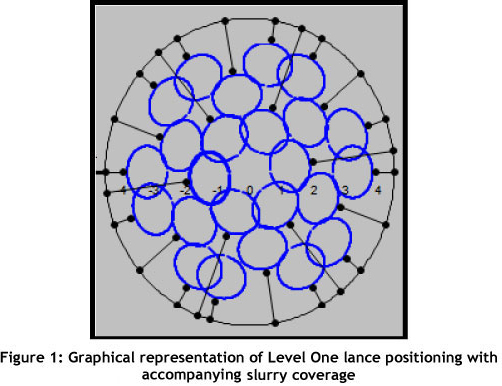
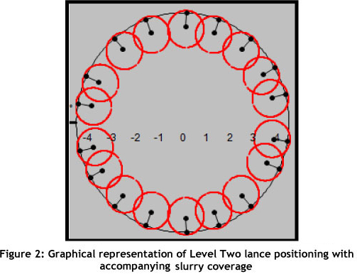
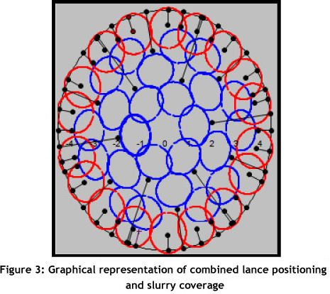
As mentioned previously, lances are nozzles that spray slurry into the drying tower; the spraying slurry forms a conical shape, represented by circles in a cross-sectional view. At present, individual operators select which lances should run, based on the required output; thus no standard operating procedure is followed. This leads to substantial variation in the coverage of slurry within the tower, as there are four shifts per day. Ultimately the efficiency of operations is negatively impacted, and more gas is burnt. Figures 1, 2, and 3 graphically represent the lance positioning in the tower.
1.3 Problem parameters
This paper aims to address the following problem parameters:
1.3.1 Too much overlap of slurry within the tower
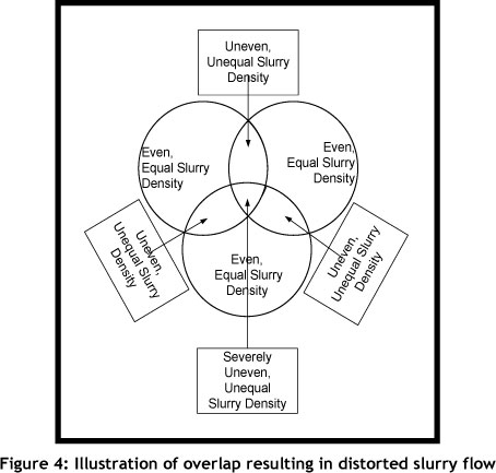
The drying ability of the slurry is inversely related to the slurry density, which is affected by slurry overlap within the tower. When the slurry overlap within the tower decreases, it dries more evenly and efficiently, leading to better powder quality by improving the consistency of the powder moisture content (PMC). As overlap occurs, the density of slurry within the overlapping space radically increases, impairing its drying ability. The more the overlap occurs, the more uneven and disrupted the flow and density of the slurry becomes. This trend is illustrated in Figure 4 below. If overlap within the tower is minimised, the slurry density will remain more constant. This has positive implications for the powder quality, and in particular for the PMC. The PMC is regulated through an automatic feedback loop, and is measured on a conveyor as it falls out of the drying tower. If the powder is too dry, less air and gas is used by the furnace; conversely, more air and gas is used if the PMC is too high. This causes oscillations in the use of air and gas. The optimum placement of lances will provide a better coverage of slurry in the drying tower, resulting in improved use of the superheated air to dry the slurry to powder.
1.3.2 Size and number of gaps in slurry
Gaps in the slurry within the drying tower create areas of 'no resistance'. As the slurry falls and the hot air rises, the hot air passes through these areas of least resistance. When this happens, the energy used to heat the air by burning gas is wasted - because the energy heats the top of the tower instead of directly drying the slurry.
1.3.3 Lack in operational uniformity
At present there is a large variation in the operation of the drying tower. With 24 operators and four shifts a day, the selection of lances operating within the tower varies greatly. This, along with the occurrence of overlap (especially overlap between the top-layered lances), gives rise to a high variation in the slurry coverage between shifts and operators. So, ideally, all overlap should be minimised: within a level it is not necessary, it impacts negatively on the efficiency of the tower, and it can easily be avoided.
The aim of this paper is to improve the efficiency of the tower through the best configuration of the lances, reducing the amount of gas used per time period to produce the desired amount of powder. To achieve this aim, a solution must be provided that eliminates all intra-layer overlap. This is especially helpful when between one and 24 lances are operating in the tower because, as long as only the top layered lances are spraying, there will be no overlap. The only variable that must be considered by the operators is the symmetrical opening of the lances. This is important because the superheated air from the furnace is pumped into the tower symmetrically. If lances operate in only one half of the tower, the hot air entering the opposite side of the tower will not directly dry out the slurry, and will thus be wasted.
As mentioned earlier, the spraying slurry forms a conical shape, represented by circles in a cross-sectional view. As discussed in Section 1.3.1, the open gaps and circle overlap must be decreased; it is thus important to position or pack the circles so that gaps and overlap are minimised. The problem described above encapsulates two distinct sub-problems: assigning the lance configuration and positioning within the drying tower, and determining a standard operating procedure that may be used to operate the furnace so that gas is used more efficiently. The top layer lance assignment problem within the drying tower has been identified as a variation of the circle packing problem.
2. LITERATURE STUDY
2.1 Introduction to the circle packing problem
The circle packing problem (CPP) is described by Lopez & Beasley [5]: "Finding the maximum radius of a specified number of circles that can be fitted, without any overlaps, into a two dimensional container of fixed size". Circle packing problems can be solved by using two distinct objective functions. First, one can aim to maximise the radius of a given number of circles within the containing shape of fixed size. Second, one can aim to minimise the size of the containing shape for a fixed number and radius of contained circles. The CPP has been used to solve problems of two and three dimensions; since the lance assignment problem is a two dimensional problem, a two dimensional version of the CPP will suffice.
The circle packing problem has been applied to a wide variety of industries and practical problems. According to Hifi & M'Hallah [3], the CPP has been found to be applicable to an array of real-world problems including the textile, manufacturing, automobile, aerospace, forestry, logistics, and food industries. For example, solutions to CPP have been successfully used in logistics, where cylindrical shapes have to be packaged optimally into a container of fixed size. The CPP has also proven to be applicable to the manufacturing industry, specifically the automotive manufacturing industry, where the smallest possible hole needs to be drilled through which to squeeze a fixed number of identical wires. This is done to keep as much structural integrity as possible without harming the wires.
Hifi & M'Hallah [3] have classified CPPs as 'NP hard' optimisation problems. An NP hard problem is defined by Mathworld as follows: "A problem is NP-hard if an algorithm for solving it can be translated into one for solving any NP-problem (nondeterministic polynomial time). NP-hard therefore means 'at least as hard as any NP-problem', although it might, in fact, be harder."
CPPs have been solved using a wide variety of algorithms, including computer-aided optimality proofs, branch and bound procedures, simulations, physical trial and error approaches, heuristics, and metaheuristics. The CPP is especially difficult to solve as the number of circles increases and when the container is circular. This is because the optimal solution may be unaffected by moving one or several of the contained circles, and is especially prevalent when a 'rattler' is present. Rattlers are defined as circles that are not fully constrained by other circles or the container, leaving them free to move within that space without affecting the optimality of the solution. Furthermore, it should be noted that (especially when the container is circular) the optimal solution can be rotated without affecting the optimality of the solution. This provides an infinite number of optimal solutions.
According to Hifi & M'Hallah [3], the CPP can be classified as a mixture of a continuous and a discrete optimisation problem. This unusual phenomenon occurs because the positions of circles within the container are continuous owing to the possible presence of rattlers, as well as rotation, reflexion, and reordering of the optimal solution. However, the structure of circles within the container is considered to be discrete.
This has led to the use of algorithms that combine local, exact optimisation searches with heuristics. Cassioli, Locatelli & Schoen [2] explore this idea in their paper, "Dissimilarity measures for population-based global optimisation algorithms".
This review will identify, discuss, analyse, and evaluate successful recent approaches to solving this problem.
2.2 Formulation space search
The formulation space search (FSS) was initially applied to the circle packing problem by Mladenovic et al. [7]. They later improved on the initial heuristic by using both Cartesian and Polar coordinates to identify the positioning of the packing circles. The number of constraints was also reduced, making the solution more efficient.
Lopez & Beasley [5] developed an altered and improved heuristic algorithm that was also based on FSS. The FSS uses different formulations of the same problem to obtain improved solutions compared with singular formulation algorithms. FSS-based algorithms are especially suited to non-linear optimisation problems. This is because a change in the formulation of the problem will change the properties of the problem. This ultimately improves the solution, because as a stationary point of one formulation is reached and the formulation of the problem is changed, the stationary point may be moved and improved on. Mladenovic et al. [7] and Lopez & Beasley [5] exploited this characteristic of optimisation by defining the positions of some circles in Cartesian and of others in Polar coordinates. Their algorithm then changes the circles that are expressed in Polar coordinates to Cartesian coordinates, and vice versa, with each iteration of the algorithm. By using this technique, Lopez & Beasley's heuristic improved on a number of previous 'optimal solutions' for certain containers. It should also be noted that they focused their efforts on developing a solution for two dimensional containers - especially circular containers. Lopez & Beasley [5] formulated the solution as follows:
Let
- C be the set of circles whose centres are expressed as Cartesian coordinates, so for circle i Є C its centre is at (xi, yi) in Cartesian coordinates.
- P be the set of circles whose centres are expressed as Polar coordinates, so for circle i Є P its centre is at (ri, θi) in polar coordinates (where C ∩ P =0; and C u P = {1, . . . ,n}).
- Q be the set of all pairs {(i, j) | i = 1,. . . ,n; j = 1,. . . ,n; i * j}.
- R be the radius associated with each of the n circles.
- Roverlap be an upper bound on R. Formally Roverlap is the maximum radius that the circles can have before they must overlap due to area considerations, defined here by equating the area of the containing unit circle (π12) to the total area of the n circles
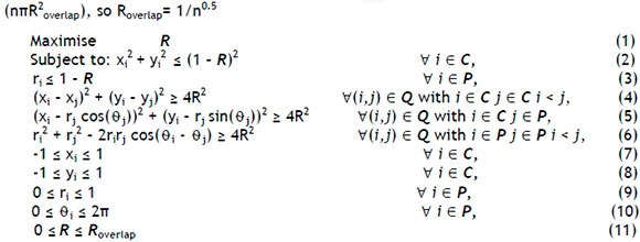
(1) The objective function of the problem
(2) Constraint ensuring that every circle is fully contained by the container circle. (Cartesian coordinate system - non-linear)
(3) Constraint ensuring that every circle is fully contained by the container circle. (Polar coordinate system - linear)
(4) Constraint ensuring that no overlap occurs between packing circles. (Cartesian coordinate system - non-linear)
(5) Constraint ensuring that no overlap occurs between packing circles. (Cartesian and Polar coordinate systems - non-linear)
(6) Constraint ensuring that no overlap occurs between packing circles. (Polar coordinate system - non-linear)
(7) Limit the variable of the x coordinate of Cartesian coordinate system
(8) Limit the variable of the y coordinate of Cartesian coordinate system
(9) Limit the variable of the radius of the packing circles
(10) Limit the variable of the angle of the packing circles; this stops equivalent solutions. (e.g.θ + k(2n) = θ)
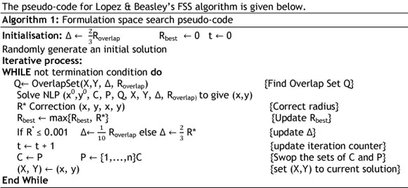
The pseudo-code provides a condensed yet simple explanation of an algorithm. The pseudocode still makes use of conventional programming language; however, its purpose is to inform readers of the operation of the algorithm. The pseudo-code is not intended for computational reading.
From this pseudo-code, the initial step is to generate a random solution for the circle packing problem. One notices that various items within the 'While' loop have not been defined in the pseudo-code.
- OverlapSet (Q): The overlap set refers to a procedure that reduces the number of nonlinear constraints that need to be performed to ensure that overlap does not occur between packing circles. This involves performing calculations that determine whether certain packing circles could overlap. This is accomplished by allowing the circles to move within a defined area to establish whether overlap is possible.
- NLP: Non-linear optimisation problem describes the following constraints: {Xi - Δ <xi> Xi + Δ} & {Yi - Δ <yi> Yi + Δ}. Delta has been defined in the initialisation phase.
- Correction: The correction step of the algorithm has a dual purpose. First, it ensures that all packing circle centres are fully contained. Second, a constant radius is established for all packing circles so that no overlap occurs between packing circles and between the -packing circles and the containing circle.
- Rbest: This step chooses the maximum radius when comparing the radius obtained from the current iteration with the radius from the previous iteration. Thus, when numerous iterations of the algorithm are completed, the optimum solution will eventually be reached and thus will not change.
The FSS of Lopez & Beasley provides the best solutions for two-dimensional containers in a time efficient manner. It should also be noted that Lopez & Beasley's [5] paper on circle packing is the most recent study done on the subject.
2.3 TomSym modelling
The circle packing problem is explored by TomSym modelling [8]. TomSym is a TOMLAB class used to model optimisation and constraint problems in MATLAB. According to the TomSym website [8], this class has the ability to solve linear, non-linear, and mixed-integer problems. The non-linear problem-solving ability is of particular interest, due to the nonlinear nature of circle equations, which is key to finding the solution to the CPP. TomSym explores the circle packing problem by inscribing a polygon within a circle. TomSym uses the logic that, by making the number of sides of the inscribed polygon arbitrarily large, this shape will represent the perfect inscribing circle. The pseudo-code for the TomSym solution is given below.
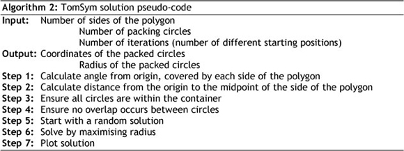
By increasing the number of sides of the polygon, its shape changes, becoming more circular. The more circular the polygon's shape, the more accurate the solution becomes. There is a relationship between the number of iterations performed and the accuracy of the solution. However, as one increases the number of sides of the polygon and the number of iterations performed, the running time of the program might be increased drastically.
The TomSym example provides an efficient, simple, easily-understood solution.
2.4 Excel simulation of Lance positioning
Microsoft Excel has long been successfully used as a tool to simulate Monte Carlo experiments. Monte Carlo simulations are defined by Investopedia as "a problem solving technique used to approximate the probability of certain outcomes by running multiple trial runs (simulations) using random variables".
Brown [1] developed a method of simulating biological systems using Excel. In-cell formulae were used, into which data could be put to provide a required output. The outputs from the formulae were then available for use as inputs in other sections of the simulation. According to Brown [1], Excel is an effective tool for simple simulations because one does not need to learn a programming language nor the specialised skills that are required to use other simulation programs. Because it is widely available and user-friendly, Microsoft Excel has been used in a wide range of study disciplines, from medicine to engineering, to simulate scenarios. Excel was used by Meineke & Brockmöller [6] to simulate pharmacokinetic models; they commented on Excel's versatility and simplicity. Brown used Excel to simulate biological systems. Lambert et al. [4] used Excel for a Monte Carlo nonlinear regression analysis by incorporating the Excel solver and various add-ins. A range of other studies have also made use of Excel as a simulation program.
2.5 Packomania website
The Packomania website was established in 1999. It contains all the best, known solutions to a wide variety of circle packing problems, and is updated whenever an improved solution is found. Packomania container shapes include circles, semicircles, squares, rectangles, and triangles. Solutions for circular shaped containers are given, from two packing circles to 1,100 packing circles. This site is widely considered to be the 'gold standard' for comparing solutions and for establishing the viability of a solution, and may be used to validate the solution proposed by this paper.
2.6 Summary
As stated in Section 2.2, the improved formulation space search by Lopez & Beasley [5] provides the best solutions for two-dimensional containers in a time efficient manner. The TomSym example may also be used as an efficient solution for the problem at hand. Both the improved formulation space search and TomSym require the use of MATLAB 7 and the add-in SNOPT (sparse nonlinear optimiser) developed by TOMLAB.
Excel has been identified as an appropriate and easy-to-use tool to simulate lance positioning within the tower. Its ease of use, availability, and ability to produce sufficient graphical simulation made it the obvious choice to illustrate the positioning of lances and slurry coverage within the tower.
3. LANCE ASSIGNMENT PROBLEM
Within the tower, each lance produces a cone of slurry as it sprays out of the nozzle. When viewed cross-sectionally, these cones take on circular shapes within the circular tower. The circle packing problem solves this problem by optimally arranging circles beginning with the top layer of lances. This ensures that in the top layer there is no overlap between cones from the top layer. Open spaces between the cones will also be minimised.
3.1 Classification of overlap
When it comes to overlapping slurry, not all overlap is considered equally detrimental to the drying of the slurry into powder. This is because some overlap is largely unavoidable, while other overlap can be easily avoided. Overlap that is easily avoided is considered to be more detrimental than unavoidable overlap. Three factors need to be taken into account when classifying the severity of the overlap:
1. Intra- / inter-layer overlap
Intra-layered overlap refers to overlap that occurs within a layer of lances - i.e. two top layered lances' slurry cones overlapping - while inter-layer overlap refers to overlap between the two layers of lances. Overlap between layers should be expected, especially in the proposed solution. This is because only the top layer lances will be optimised, and the bottom layer lances will be positioned in the gaps created by the top lances.
2. Area of overlap
The area of overlap refers to the extent of overlap between slurry cones. The greater the area of slurry cone overlap, the more detrimental the effect on the drying capability of the superheated air. Thus the area of overlap between cones should be minimised.
3. Number of overlapping cones (cross-sectionally represented as a circle)
The number of overlapping cones has an impact on the slurry density and thus the drying ability of the slurry.
The combination of these three factors has led to the decision that overlap should be classified. By classifying the types of overlap, a fair comparison can be made between the current and the proposed positioning of lances. Taking all three aspects into account produces the following classification system:
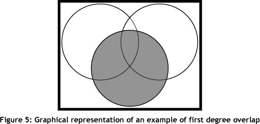
First degree overlap: First degree overlap (FDO) is defined as overlap that occurs between three slurry cones, including all bordering slurry between any two of the three cones. First degree overlap will always be a combination of intra- and inter-layered overlap. First degree overlap severely disrupts the flow and density of slurry within the tower, with a significant impact on the PMC and power quality. Figure 5 illustrates an example of FDO: the white circles represent slurry cones originating from top layered lances, while the grey circle represents cones originating from bottom layered lances. Because of the presence of a third overlapping circle, the overlap between any two of the three circles is considered to be FDO.
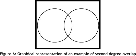
Second degree overlap: Second degree overlap (SDO) is defined as any intra-layered overlap, regardless of the size of overlap. This classification system does not take the size of this overlap into account, because all intra-layered overlap is avoidable. Figure 6 illustrates SDO.
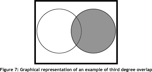
Third degree overlap: Third degree overlap (TDO) refers to any inter-layered overlap. The third degree overlap is ranked according to the area of the overlap. Figure 7 shows an example of TDO; this is overlap between cones originating from different layered lances.
3.2 Classification of open spaces
As with overlap, not all open spaces within the drying tower are considered equally detrimental to the slurry drying process. There are only two factors to consider when classifying the severity of open spaces:
- Size
The larger the size of the open space, the more superheated air 'escapes' through space. This leads to inefficiency within the tower.
- Shape
The more circular the shape of the open space, the easier it is to remedy the predicament by simply positioning another lance at the centre of the opening.
Combining these factors leads to the following classification of open spaces within the tower:
First degree spaces: First degree spaces (FDS) are defined as circular-shaped spaces that can accommodate at least 80 per cent of a lance cone. FDS should not be present, as the amount of neglected coverage has too severe an impact on the amount of escaped air.
Second degree spaces: Second degree spaces (SDS) are classified by their irregular shapes and relatively small surface area. Gaps occurring directly next to the drying tower are considered unavoidable and negligible.
Third degree spaces: Third degree spaces (TDS) are defined as small spaces that are unavoidable when packing circles. These spaces are generally convexly triangular-shaped, and form when three circles are tightly packed. TDS also occur adjacent to the tower wall. By having a classification system for the open spaces within the tower, the current system can easily be compared with the proposed lance configuration.
4. SOLUTION APPROACH
The initial step in solving the lance positioning problem is to choose the correct algorithm. The improved formulation space search by Lopez & Beasley [5] was found to provide the best theoretical solution to the lance positioning problem. The TomSym example of the circle packing problem was also identified as a high-quality solution to the problem. It was decided that these two methods were the best to use, given the software they use and the results they obtain. As mentioned in Section 2.6, both the above-mentioned solutions require the use of MATLAB 7 and the add-in SNOPT (sparse nonlinear optimiser) developed by TOMLAB.
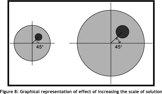
Once the solution is found, it is important to recognise that the solution is given for a unit circle - i.e. a circle with a radius of one. All results should then be transformed to apply to a nine metre diameter circle. Even though the size will be different, the position of the contained circles will remain unchanged. For the conversion from the unit circle to the nine metre diameter circle, either Polar or Cartesian coordinates may be used. In Polar coordinates, the conversion of the container circle size will have an impact on the radius, but not on the angle. This concept is illustrated in Figure 8 below. Alternatively, when using Cartesian coordinates, the circle centre and the radius of each circle are altered by simply multiplying by the increase in radius - in this case, 4.5.
Once the positioning of the lances has been completed for the circle with a radius of 4.5 metres, a comparison of the differing configurations will be done.
The radius of the slurry circles within the tower will provide the necessary information to calculate the vertical distance from the lance. If this distance is too great, tapering of slurry comes into play, thus rendering the solution inaccurate. It has been established that the maximum radius attained by falling slurry after tapering is equivalent to the radius at a vertical distance of 1.35m below the lance when tapering is not taken into account. This will be the reference point for all calculations of overlap within the tower.
The number of top lances is restricted to 24 for a number of reasons. Increasing the number of top lances beyond 24 makes maintainability problematic; and Company ABC have stated that, for operational reasons, the number of lances per layer should not be altered.
The results are simulated in Microsoft Excel and MATLAB, providing a clear view of where the remaining open spaces within the tower are. As a total of 42 lances must be positioned within the tower, the remaining lances (42-24=18) will then be positioned as the bottom layer of lances in the largest of the open spaces within the tower. Following the positioning of the bottom layered lances, the solution, and the current lance positioning, are simulated. Overlap and open space are then measured according to the classifications mentioned above.
5. PROPOSED CONFIGURATION
Both the FSS algorithm and the TomSym model were constructed in an attempt to find an efficient solution to the problem at hand. The two models were then compared to identify which provided the better solution.
The FSS developed by Lopez & Beasley (2011) is constructed using MATLAB and the add-in SNOPT developed by TOMLAB. Initialisation is the first step of the FSS algorithm. This step requires a random generation of the positions of the circles. This randomly-generated solution is then improved during subsequent iterations. Information obtained from the Packomania website will be used as a starting point in the search for a solution to the lance assignment problem. The position of the current best, known solution for circles will be adopted as the random starting point when using the heuristic developed by Lopez & Beasley.
The solution obtained by the TomSym model, however, was identified as the better solution, and is thus the proposed solution. The TomSym solution proved to be much more time efficient, providing a better solution in a shorter time. The TomSym model was run for a polygon with 1,500 sides; this provides the optimal positioning for the top lance layer, as seen by the white circles in Figure 6.
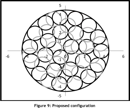
The proposed solution aims to balance the amount of open space and overlap. This is achieved by optimising the positioning of the top layer of 24 lances. The placement of the bottom layer of lances is then done by positioning the lances in the areas of biggest overlap. It is obvious that a solution without overlap or open spaces is impossible when packing circles into any container; but by using this technique, a very good solution is attained.
Figure 9 below illustrates the proposed configuration to be analysed. The black and grey circles represent the slurry coverage originating from the top and bottom layers of lances respectively.
6. ANALYSIS OF PROPOSED CONFIGURATION
6.1 Overlap analysis
The calculation of overlap within the proposed solution is based on the rules of trigonometry and geometry.
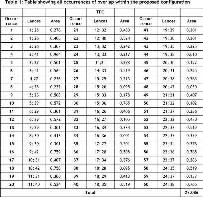
Table 1 illustrates all the occurrences of overlap within the proposed solution. When examining the proposed configuration, notice that no intra-layered slurry overlap occurs. The absence of intra-layered overlap means that all overlap within the tower will be classified as TDO. The lack of intra-layered overlap is intentional, and leads to a more even drying of the slurry within the tower. There are 68 instances of overlap (all TDO), with a total of 23.086m2 of overlapping area.
6.2 Open space analysis
Using an Excel simulation of the positioning of lances and the accompanying slurry overlap, the position and relative size of the open spaces between the circles is easily identified. Figure 6 shows the positions and sizes of all the open spaces within the tower. These spaces are small, and are generally directly adjacent to the container wall, which makes them largely unavoidable without severely impacting on the amount of overlap within the tower. All the open spaces fall into the TDS classification owing to their size and roughly triangular shape.
Since the positioning of the top layer of lances is optimal and is done before the positioning of the second layer, these positions are fixed. Thus the positioning of the bottom layer of lances has a significant impact on the number and size of open spaces within the configuration. The objective of the bottom layer is to maximise the coverage of slurry within the tower while minimising the overlap between lances. This objective is attained by positioning the second layer of lances in the gaps between the top layer of lances.
The positioning of the bottom layer of lances is calculated using Polar or Cartesian coordinates, depending on the positioning of each lance relative to the others. Figure 6 illustrates the positioning of the bottom layer of lances within the proposed configuration, represented by grey circles.
6.3 Configuration comparison
When comparing the current and proposed configurations, one must ensure that the radii of the packing circles are equal. An equal radius of packing circles for each configuration indicates that the vertical distances from the lance to the point of measurement are equal. The initial radius of the proposed configuration was 0.0015m (1.5mm) larger than that of the current positioning, which means that the vertical distance is slightly more than for the current configuration. This difference would not have had a significant impact on the measurements. It was decided, however, that the radii should be exactly the same, allowing an unbiased comparison, and that the circle sizes should be equivalent. Thus 3mm was subtracted from the diameter of each circle in the proposed solution.
Figure 10 below shows the positioning of lances and slurry coverage of the top layer of lances for the current and the proposed positioning of lances within the tower. This diagram shows that there is top layer overlap in the current positioning, but not in the proposed positioning. The proposed positioning of the top layered lances also has fewer and smaller open spaces than the current positioning. These improvements will have a positive impact on the amount of gas burnt within the furnace to dry slurry to powder.
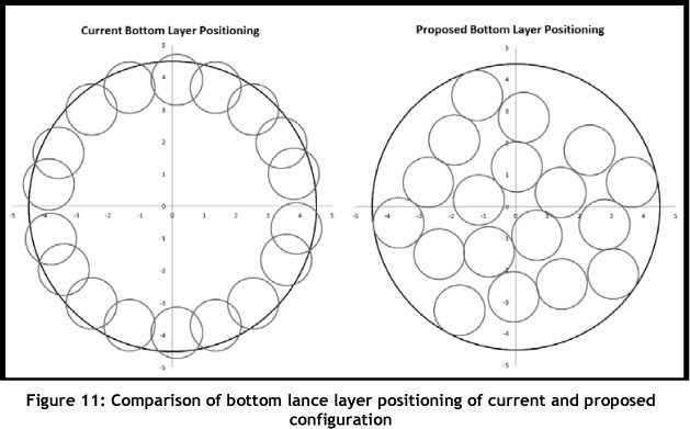
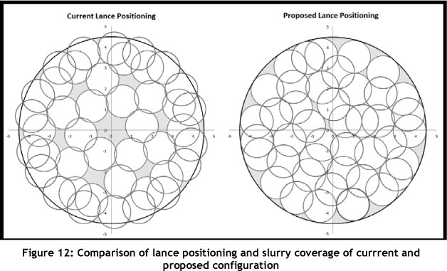
Figure 11, shown below, is used to compare the current and the proposed positioning of the bottom layer. The current positioning of the bottom layer of lances causes slurry to strike the side of the tower. This causes a mixture of slurry to 'bounce' off the side of the tower. This leads to an uneven density of slurry, ultimately causing uneven drying. In addition, the current positioning of the bottom layered lances allows an intra-layered overlap of the bottom layer. This overlap negatively impacts on the drying ability of the affected areas of overlap. And the more overlap (especially intra-layered overlap) that occurs, the more open spaces result from the inefficient use of slurry coverage. The proposed solution, however, does not have any instances of intra-layered overlap. This feature of the proposed configuration makes it possible to deal with, and reduce, the open spaces within the tower. Figure 12 illustrates the complete configuration for the current and the proposed lance positioning. The current configuration of lances produces 26.033m2 of overlap, while the proposed solution produces only 23.086m2 of overlap. The difference is 2.947m2. This may seem rather small, but, when calculating the area of one slurry circle (A = πr2 = π * 4.52= 1.976m2), this difference appears more significant. The proposed solution also shows distinctly fewer open spaces than does the current slurry coverage. In effect, by reducing the number of open spaces within the tower, less superheated air will escape through the gaps in the slurry.
In Figure 12, open spaces are highlighted for ease of comparison. From the diagram, one notices that the current positioning has a larger total of overlap than the proposed solution. It is also apparent that the majority of the open spaces in the proposed solution are located around the outside of the tower. This would also be the case in the current solution if the slurry originating from the bottom layer of lances were not 'overlapping' with the tower wall.
The proposed solution provides better slurry coverage than does the current configuration: it reduces both the amount of overlap within the tower and the area of the open spaces within the tower, and it does not spray slurry against the side of the tower.
7. CONCLUSION
The proposed solution aims to improve the efficiency of the tower's operations by reducing the amount of gas burnt to convert slurry into base powder within the required PMC. The problem has been solved by applying operations research techniques to solve a variation of the circle packing problem, using Microsoft Excel simulations to gain insight into the current and proposed configurations, and employing mathematical formulae for the placement of the bottom layered lances. The aim of decreasing the amount of slurry overlap and the number of open spaces within the tower is sufficiently solved, providing Company ABC with the following benefits:
- Decreased overlap of slurry within the tower: Company ABC will experience a decrease in the consumption, and more even usage, of natural gas within the furnace. Gas is Company ABC's biggest expense in producing washing powder; by reducing the amount of gas burned, Company ABC can expect some savings in expenses.
- Decreased size and number of gaps in slurry: The size and number of gaps is decreased by changing the positioning of the lances within the tower, once again saving an immense amount of gas. The factory runs almost continuously, day and night, almost all year round. A small hourly saving on gas will quickly become substantial when the tower runs 150 hours a week.
All the results were validated to ensure the correct positioning of the lances. For validation purposes, the solution is compared with the 'gold standard' set by the Packomania website. This comparison showed the TomSym solution to be valid. Although the positioning of the circle was not identical, the radius attained from this solution using a polygon with 1,000 sides and 50 different starting positions deviated by less than 0.000001m from the 'gold standard' - a discrepancy that is not problematic in the context of slurry coverage. In addition, the solution could be improved by increasing the number of iterations and sides of the inscribed polygon. The increased accuracy would not be significant, however, and the time needed to run the model would increase significantly.
Implementation of the project will reduce the amount of gas that has to be burnt to dry out the slurry. This will drastically reduce Company ABC's gas expenses and its impact on the environment.
REFERENCES
[1] Brown, A. 1997. A methodology for simulating biological systems using Microsoft Excel. Computer Methods and Programs in Biomedicine, 58, pp 181-190. [ Links ]
[2] Cassioli, A., Locatelli, M. & Schoen, F. 2010. Dissimilarity measures for population-based global optimisation algorithm. Computational Optimization and Applications, 45(2), pp 257-281. [ Links ]
[3] Hifi, M. & M'Hallah, R. 2009. A literature review on circle and sphere packing problems: Models and methodologies. Advances in Operations Research, pp 1-22. [ Links ]
[4] Lambert, R.J., Mytilinaios, I., Maitland, L. & Brown, A.M. 2011. Monte Carlo simulation of parameter confidence intervals for non-linear regression analysis of biological data using Mircosoft Excel. Computer Methods and Programs in Biomedicine, 107(2), pp 1-9. [ Links ]
[5] Lopez, C.O. & Beasley, J.B. 2011. A heuristic for the circle packing problem with a variety of containers. European Journal of Operations Research, 214(3), pp 512-525. [ Links ]
[6] Meineke, I. & Brockmoller, J. 2007. Simulation of complex pharmacokinetic models in Microsoft Excel. Computer Methods and Programs in Biomedicine 88(3), pp 239-245. [ Links ]
[7] Mladenovic, N.P. 2005. Reformulation descent applied to circle packing problems, Computers and Operations Research, 32(9), pp 2419-2434. [ Links ]
[8] Tomsym Modeling. 2008-2011. http://www.tomsym.com/matlab_model_library.html [accessed September 12, 2011]. [ Links ]
* Corresponding author
1 The author was enrolled for a B Eng (Industrial) degree in the Department of Industrial and Systems Engineering, University of Pretoria.

