


Serviços Personalizados
Artigo
 Inglês (pdf)
 Artigo em XML
 Referências do artigo
Indicadores

Links relacionados
-
 Citado por Google
 -
 Similares em Google
Compartilhar

 Permalink
South African Journal of Industrial Engineering
versão On-line ISSN 2224-7890
versão impressa ISSN 1012-277X
S. Afr. J. Ind. Eng. vol.24 no.1 Pretoria Jan. 2013
Robust localisation of automated guided vehicles for computer-integrated manufacturing environments
R.C. DixonI, 1, *; G.BrightII; R. HarleyIII
IDepartment of Mechanical Engineering University of KwaZulu-Natal, South Africa. 205504598@ukzn.ac.za
IIDepartment of Mechanical Engineering University of KwaZulu-Natal, South Africa. brightg@ukzn.ac.za
IIISchool of Electrical and Computer Engineering Georgia Institute of Technology, United States of America. Ronald.harley@ece.gatech.edu
ABSTRACT
As industry moves toward an era of complete automation and 'mass customisation', automated guided vehicles (AGVs) are used as material handling systems. However, the current techniques that provide navigation, control, and manoeuvrability of automated guided vehicles threaten to create bottlenecks and inefficiencies in manufacturing environments that strive towards the optimisation of part production.
This paper proposes a decentralised localisation technique for an automated guided vehicle without any non-holonomic constraints. Incorporation of these vehicles into the material handling system of a computer-integrated manufacturing environment would increase the characteristics of robustness, efficiency, flexibility, and advanced manoeuvrability.
OPSOMMING
Outomaties geleide voertuie (OGVs) word gebruik in materiaalhanteringstelsels soos wat industrie na 'n era van outomatisering en 'massa aanpassing' beweeg. Die huidige tegnieke wat sorg vir navigasie, beheer, en beweegbaarheid, hou die bedreiging van bottelnekke en ondoeltreffendheid in vir vervaardigingsomgewings wat streef na optimisering van onderdeelproduksie.
Hierdie artikel hou 'n gedesentraliseerde lokaliseringstegniek voor vir 'n OGV sonder enige nie-holonomiese beperkings. Implementering van dié voertuie in die materiaalhantering-stelsel van 'n rekenaar geïntegreerde vervaardigingsomgewing sal eienskappe soos robuustheid, doeltreffendheid, buigbaarheid, en gevorderde beweegbaarheid verbeter.
1. INTRODUCTION
In order to gain a competitive advantage in today's high-tech industries, part manufacturers have to take advantage of new technologies. These modern technologies attempt to combine the idea of flexible manufacturing systems (FMS) with well-known mass production manufacturing techniques. This combination has become known as 'mass customisation' manufacturing, and aims to achieve a vast variety of products at mass production rates.
The transportation of material and parts within a 'mass customisation' manufacturing environment plays a huge part in overall efficiency. A material handling system that provides flexibility, robustness, and high efficiency will have to be designed as 'mass customisation' becomes a reality of the future.
The use of mobile robots, known as automated guided vehicles (AGVs), is a well-known technique for material handling in manufacturing [1]. However, traditional techniques for the navigation and control of automated guided vehicles can cause bottlenecks in the manufacturing process. They add a level of flexibility to a manufacturing system, compared with conveying systems. By taking advantage of modern and well-known navigation techniques - thereby providing greatly improved flexibility, robustness, and efficiency -automated guided vehicles will become the popular choice in a 'mass customisation' manufacturing environment.
Localisation through the Kalman filter has become a research topic and a well-known solution to the navigation of mobile robots [2]. The Kalman filter allows for stochastic state estimation from multiple noisy sensor measurements in linear and nonlinear dynamic systems [3]. This paper aims to introduce a navigation technique for an omnidirectional robot using the discrete Kalman filter. It will greatly increase the efficiency, robustness, flexibility, and manoeuvrability of automated guided vehicles in a part manufacturing environment.
2. OMNIDIRECTIONAL MOBILE ROBOT PLATFORMS
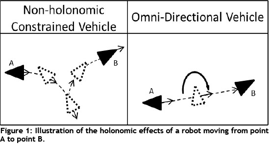
Non-holonomic constraints are those that prohibit a vehicle from having direct control over each of its degrees of freedom. For example, a car cannot simply move sideways into parallel parking: it has to go through a series of movements in order to achieve the desired result. An omnidirectional vehicle (or holonomic vehicle) can, however, move directly into parallel parking.
2.1 Omnidirectional vehicle
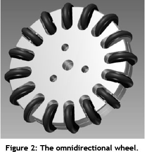
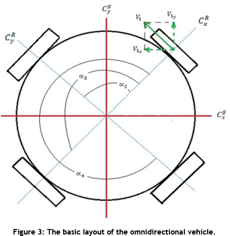
The mobile platform used for the purposes of this paper was designed with omnidirectional wheels (Figure 2 below). This allows the wheel to move in longitudinal and lateral directions. The four wheels are spaced 90 degrees apart, and perpendicular to each other around the periphery of the robot platform (Figure 3). This decreases the complexity of the kinematic model derivation due to the symmetry of the wheels across the robot's local coordinate axis. This design allows for direct control over all three degrees of freedom of the vehicle, and can therefore be considered completely omnidirectional.
3. PROBABILISTIC LOCALISATION
"Mobile robot localisation is the problem of determining the pose of a robot with respect to a given map." [4]
Probabilistic localisation techniques take into consideration the uncertainty with which a robot could be in a specific pose at a certain time. The general problem is described by a probability distribution of the robot being at pose at time step k=0, given the folllowing: all external measurements from the initial time step k = 0 to the current time step ;(z0.k) all control inputs until the current time step (u0:k); the map (m) of landmarks in the global coordinate system; and the pose of the robot one time step before (xk-1). The probability is represented by a multivariable normal distribution, shown in equation 1.

Modern probabilistic robot localisation techniques use kinematic models of the robot motion as opposed to dynamic models. Successful use of kinematic models in the real world implementation of probabilistic localisation techniques makes it unnecessary for the dynamics of the robots to be modelled. This, however, does not mean that the robot dynamics cannot be used for probabilistic localisation [4].
3.1 Kinematics
The system equations for the discrete Kalman filter can be implemented in two ways. The first technique uses the velocity inputs to the robot's wheel, and the second technique uses the wheel velocities read by the robot's odometry sensors [4]. For the purposes of this paper, quadrature encoders are attached to each wheel, and therefore the actual measured wheel velocity will be used as the inputs to the prediction phase of the Kalman filter.
Figure 3 below is a simple representation of the base of the robot and its omnidirectional wheels. ∞i; is the angle between the ith wheel and the x-axis of the robot's local coordinate system CR . Cg represents the global coordinate system within which the robot moves freely.
The kinematic equations of the vehicle map the relationship between the angular wheel velocities of the robot and the global velocities of the robot. A full derivation of a similar omnidirectional platform can be found in van Haendel [5].
3.1.1 Inverse kinematics
The inverse kinematics of the robot platform determine the wheel angular velocities, given the global velocities of the vehicle, in the form of equation 2 below, where A is the transformation matrix that maps the global velocities to the wheel angular velocities, and is the global velocity vector of the robot platform.

Equation 3 shows matrix A for a mobile robot platform with four omnidirectional wheels of radius r and three degrees of freedom; it is therefore a 4x3 matrix.
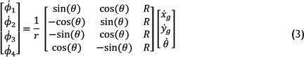
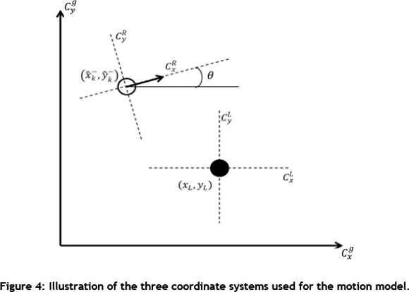
R is the distance between the centre of the mobile platform and the wheels, is the angular velocity of the ith wheel in radians per second, and θ is the angle between the robot's local x-axis and the x-axis of the global coordinate system, as shown in Figure 4.
3.1.2 Forward kinematics
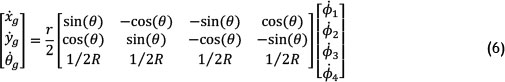
The forward kinematics equation is derived by inverting the matrix A from the inverse kinematics, and determines the global velocities of the mobile platform as a function of the wheel angular velocities, as shown in equation 4.

A is a 4x3 matrix, and therefore cannot be inverted directly; the Moore-Penrose pseudoinverse A+ needs to be obtained by using equation 5 [6]. The complexity of the pseudoinverse can be dramatically reduced by placing the wheels symmetrically across both the x- and the y-axis of the robot's local coordinate system. Therefore ∞c1=0°, ∞2= 90°, ∞3= 180°, and ∞4= 270°. The pseudoinverse A+ can now easily be determined.
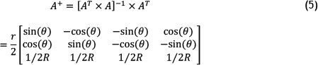
The forward kinematic equation is therefore:
3.2 The discrete Kalman filter
The Kalman filter is a recursive data processing algorithm that is able to estimate accurately the state of noisy linear dynamic systems in a way that minimises the mean squared error [7,3]. The filter was first introduced by Rudolf Kalman in 1960 [8], and has since been adapted for nonlinear systems and used in a great variety of applications.
A common adaption to the Kalman filter is the extended Kalman filter. It is suitable for nonlinear dynamic systems, as it creates a linearised estimate about the points of interest through Taylor series expansion [7].
The discrete linear Kalman filter and discrete extended Kalman filter are two part recursive algorithms. First, the state prediction or 'time update' is computed (this is discussed in section 3.2.1), and second, the state correction or 'measurement update' is computed (as discussed in section 3.2.2).
3.2.1 Kinematic system model and state prediction
The state prediction or time update determines the state mean  and priori state covariance over all possible states the robot could be in, relative to the posterior estimated state from one time step before
  , and the control input read from the odometry or internal sensors. This probability distribution is represented by a system model in the form of equation 7.

This mean state is known as the priori state estimation  and is determined by equation 8.

Therefore the state of the omnidirectional mobile robot system can be estimated. This is a nonlinear equation, and therefore has to be linearised in order to determine the priori state mean.
Due to random noise in the form of wheel slip, inaccurate odometry measurements, etc., the priori state estimation is given as:

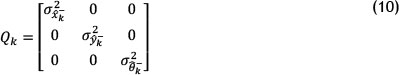
where wk is the modelled random white (zero mean) system noise with error covariance Qk, and represents the degree of uncertainty in the state prediction. The noise on each state variable is said to be independent of the noise on each of the other state variables. The off-diagonal elements of the error covariance matrix Qk are therefore zero, as shown in equation 10.
From equation 9 and equation 13 (backward Euler integration), it can be determined that the priori state estimation can be represented as:
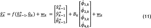
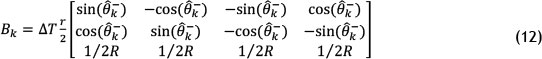
where Bk, adapted from equation 6, is:

The priori state error covariance is then calculated as:

where
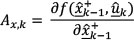
and
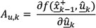
and where Uk is the control input error covariance, and represents the degree of uncertainty in the measurement received from the odometry sensors (quadrature encoders).
3.2.2 Measurement model and state correction
External measurements (known as absolute measurements) taken by the robot of the environment form the basis of the state correction stage of the discrete recursive Kalman filter. These measurements can be made by range sensors or visual sensors, and are considered to be subject to guassian distributed, zero mean, independent noise. For the purposes of this paper, the sensor is considered to be an 'all state' sensor, and can therefore determine the noisy state of the environment with one observation of one landmark from one sensor.
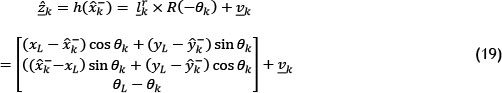
The measurement model given by the probability distribution in equation 15 determines the mean measurement observation and covariance over all possible observations, given priori state estimation and the position of all observable landmarks m.

This probability distribution is represented by the measurement model:

where h is a nonlinear equation that maps the priori state estimates of the robot and the known positions of the landmarks compared with what the robot should observe. is the modelled guassian distributed, zero mean, independent noise acting on the observation sensor, and is represented by the error covariance Rk.
Figure 4 shows the three coordinate systems: the robot's coordinate system CR, the landmark's coordinate system CL, and the global coordinate system Cg. For the purpose of this paper, the measurement model will determine the landmark's coordinates in the robot's coordinate system.
The difference in state between the robot and the known landmark is given as:
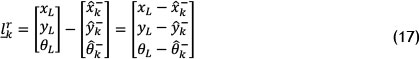
In order to obtain the coordinates of the landmark in the robot's coordinate system, we require a coordinate system transformation. This is easily done, assuming that a unit length in the landmark's coordinate frame is the same as a unit length in the robot's coordinate frame.
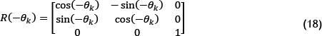
 is a rotation matrix about the vertical axis of the robot's platform over a rotation
  . By multiplying the rotation matrix by the difference in the landmark and robot state's
  we transform the landmark's coordinates into the robot's coordinate system.
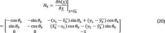
The extended Kalman filter is used for nonlinear type system and measurement models. The measurement model is clearly a nonlinear function, and therefore requires linearisation about the points of interest. Linearisation is calculated through a Taylor expansion approximation of the measurement model at the predicted priori state estimation or mean .
.
The Kalman gain Kk is computed, and determines the extent to which the measurement would be used in the update of the priori state estimation, based on the degree of uncertainty in the state prediction and external measurements. If the measurement error covariance Rk is relatively large, then the state update would be less noticeable. On the other hand, if the system error covariance Qk is large, then measurements taken by the sensors would be used to a greater extent, and the effect of the measurement on the posterior state estimation would be large.
The Kalman gain for the extended Kalman filter is calculated as follows:

The posterior state error covariance  used for the priori error covariance prediction in the next time step k + 1 is given by:

Finally, the posterior state estimation is determined, where zk is the actual, noisy measurement made by the all state sensor, and
  is the predicted measurement made by the measurement model.

The posterior state estimation is then carried over to the next time step and used for the system state prediction. In this way the recursive nature of the discrete Kalman filter is observed.
4. IMPLEMENTATION AND RESULTS
Implementation of the discrete Kalman filter requires a system model and a measurement model, as well as initial conditions for the robot state and error covariance. Once these have been determined, the recursive algorithm can easily be used.
A simulation of the Kalman filter working with the omnidirectional robot and its derived equations as above was carried out in Mathwork's SIMULINK. By empirically adjusting the values for the system error covariance Qk, measurement error covariance Rk, and control input error covariance Uk, a suitable Kalman estimation of the robot's pose can be determined.
The sources of noise affecting the robot as it moves are:
- Slippage of the wheels. This does not affect the estimated position of the robot, as the kinematic models do not take the slip into consideration. It does, however, affect the actual position of the robot, and will therefore affect the observations made by the sensors. The control input is therefore not an accurate estimate of the robot's actual position.
- The latency of the quadrature encoder interrupts routines, especially for high resolution encoders with slow microcontrollers. This does not affect the actual position of the robot, but does affect the predicted priori state estimate as well as the predicted measurement model.
- Observation sensor noise. This noise source only affects the actual observation made by the robot.
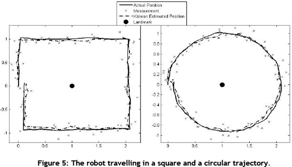
The simulation was run for a square control input and a circular control input. The robot travels around, but always facing the landmark situated at (1,0) in the global coordinate system. In each case the actual pose, the sensor observations (measurements), and the Kalman estimate were obtained. The effects of slip can be seen in the way that the robot does not travel in a perfect square or a perfect circle. Figure 5 below shows how the Kalman estimated pose of the robot tracks closely to the actual pose as it moves around the landmark, even with the relatively noisy sensor measurements.
5. FUTURE WORK
Localisation techniques can form the basis of mobile robot applications. Once accurate localisation has been achieved, it can be used as a platform for further research and development of motion planning and coordination. The decentralised nature of the probabilistic algorithms makes it suitable for applications in the emerging research of swarm robotics.
Simultaneous localisation and mapping (SLAM) would increase the flexibility of the navigational algorithms, but at the cost of computational power. A way forward would be:
- To move towards simultaneous localisation and mapping, not localisation alone.
- To allow for complete independence of the platform - i.e. no centralised control.
- To incorporate swarm intelligence algorithms for motion planning, multi-agent cooperation, and task allocation in the manufacturing environment.
This would produce a highly flexible, efficient, robust, and scalable material handling system that could be adapted to meet ever-changing product demands in a 'mass customisation' manufacturing environment.
6. CONCLUSION
The extended Kalman filter was implemented as the probabilistic localisation technique of an omnidirectional mobile robot. This technique showed encouraging results in a simulation. If incorporated into a suitable feedback control loop, the effects of slip noise and sensor noise could be eradicated.
Probabilistic localisation is still a new science in the mobile robot technology domain. Research has shown that successful implementation of these localisation techniques into automated guided vehicles in a manufacturing environment is an essential step towards full flexibility and high production rates. The Kalman filter provides a robust landmark navigation solution, while the omnidirectional platform supplies advanced manoeuvrability and simpler control. The system provides increased flexibility, robustness, manoeuvrability, and, ultimately, efficiency in a computer-integrated manufacturing environment.
REFERENCES
[1] Groover, M.P. 2008. Automation, production systems and computer-integrated manufacturing. Upper Saddle River: Pearson. [ Links ]
[2] Durrant-Whyte, H. & Bailey, T. 2006. Simultaneous localisation and mapping (SLAM): Part 1 The essential algorithm, IEEE Robotics and Automation Magazine, Vol. 2. Available at: http://citeseerx.ist.psu.edu/viewdoc/summary?doi=10.1.1.128.4195. [ Links ]
[3] Negenborn, R. 2003. Robot localization and Kalman filters. Institute of Information and Computer Science, Utrecht University. Copenhagen, Masters thesis. Available at: www.negenborn.net/kal_loc. [ Links ]
[4] Thrun, S., Burgard, W. & Fox, D. 2006. Probabilistic robotics. Massachusetts: MIT Press. [ Links ]
[5] van Haendel, R. 2005. Design of an omnidirectional universal mobile platform. Eindhoven, DCT traineeship report. [ Links ]
[6] Penrose, R. 1955. A generalized inverse for matrices. Cambridge: Cambridge University Press. [ Links ]
[7] Welch, G. & Bishop, G. 2006. An introduction to the Kalman filter. Department of Computer Science, University of North Carolina. Chapel Hill. [ Links ]
[8] Kalman, R. 1960. A new approach to linear filtering and prediction problems. Journal of Basic Engineering. [ Links ]
* Corresponding author
1 The author was enrolled for an MSc (Mechanical Engineering) in the Department of Mechanical Engineering, University of KwaZulu-Natal.

