


Servicios Personalizados
Articulo
 Inglés (pdf)
 Articulo en XML
 Referencias del artículo
Indicadores

Links relacionados
-
 Citado por Google
 -
 Similares en Google
Compartir

 Permalink
South African Journal of Industrial Engineering
versión On-line ISSN 2224-7890
versión impresa ISSN 1012-277X
S. Afr. J. Ind. Eng. vol.23 no.3 Pretoria ene. 2012
GENERAL ARTICLES
High-speed 5-axis machining for tooling applications#
M. SaxerI, *; N. de BeerII; D.M. DimitrovIII
IInstitute for Advanced Tooling, Department of Industrial Enginxeering, Stellenbosch University, South Africa. mikesaxer@sun.ac.za
IILaboratory for Rapid Product Development, Department of Industrial Engineering, Stellenbosch University, South Africa. ndebeer@sun.ac.za
IIIInstitute for Advanced Tooling, Department of Industrial Enginxeering, Stellenbosch University, South Africa. Laboratory for Rapid Product Development, Department of Industrial Engineering, Stellenbosch University, South Africa. dimitrov@sun.ac.za
ABSTRACT
In the modern metalworking industry, production moulds often have complex geometry, with undercut regions, small corner radii, sharp edges, deep cavities, or large cores. Conventional manufacturing process chains to machine these complex features are often lengthy and inefficient due to multiple steps. This article presents current results obtained through industry projects and experimental work using 5-axis high-speed machining with high-end CAD/CAM systems to improve process efficiency. Cost optimisation and lead time shortening can be clearly shown. This is of particular importance for South African manufacturing companies, where multi-axis HSC technology - although not totally unknown - is significantly under-used.
OPSOMMING
In die moderne metaalnywerheid word produksiegietvorms dikwels gekenmerk deur komplekse geometrië, bv. ondersny areas, klein hoek radiusse, skerp rante, diep holtes, en groot kerne. Konvensionele vervaardigingsproseskettings om hierdie komplekse kenmerke te masjieneer is dikwels langdurig en ondoeltreffend weens veelvuldige stappe. Hierdie artikel dui op resultate verkry vanaf industrie-verwante projekte, sowel as eksperimentele werk, waar 'n 5-as hoë spoed freesmasjien gebruik was tesame met top reeks CAD/CAM stelsels om prosesdoeltreffendheid te verbeter. Koste optimisering en verkorting van lei tye kan duidelik getoon word, wat van besondere belang is vir Suid-Afrikaanse vervaar-digingsmaatskappye wat van multi-as hoë spoed masjieneringstegnologië gebruik maak.
1. INTRODUCTION
The development of innovative products, and their realisation through advanced manufacturing methods and process combinations, is a key issue in international competitiveness [1]. In the field of the new rapid technologies, represented today mainly through various rapid prototyping and manufacturing methods, the progress of the highspeed cutting (HSC) technology is of distinct importance. It is often compared with the potential advantages arising from direct tool or component production by additive manufacturing methods such as SLS (selective laser sintering), SLM (selective laser melting), or 3DP (three dimensional printing). The major advantage of these methods is their unrestricted ability to produce shapes of almost any complexity. The most important advantage of the HSC technology, however, is that nearly all kinds of materials used in the manufacturing industry can be efficiently processed. The efficient production path of a tool direct from a CAD-file, in conjunction with simultaneous 5-axis machining, considerably reduces the complexity found in conventional manufacturing methods [2, 3]. These advantages have led to a broad variety of specific applications, especially in high-tech industries such as the aircraft (engines and bodies) and automotive industries [4, 5, 6].
In these industries, products are usually highly sophisticated in their geometry and material choice, to fulfil the high demands of their intended use. These demands regarding safety, quality, and weight reduction - as well as the use of materials that are difficult to machine - constrain the increase in efficiency of conventional production technologies. Production runs are therefore often characterised by long process chains and a variety of manufacturing methods. Substantial savings on operating time and costs can become possible only by shortening the process chain. This can be achieved by applying advanced and innovative manufacturing methods, such as simultaneous multi-axis material removal, which often allows the complete machining of a component in a single set-up. A further application of the multi-axis HSC technology is the manufacturing of moulds and dies, especially of complex cores and cavities. It has to be remembered that - being a cross sector industry - the machining operations of moulds and dies worldwide represent a great percentage of the total production time, thus impacting on efficiency [7, 8].
There is a drastic need for systematic research into improved and more efficient use of this technology, especially as it relates to the machining of some of the most important materials in the aerospace and automotive industries: composites and light metals -magnesium, titanium, aluminium - and their alloys, as well as resins and steel alloys applicable to the tooling industry. In this way, the targeted cost optimisation and lead time shortening could be modelled and practically achieved [9, 10, 11]. This is of particular importance for South African manufacturing companies involved in related industries, where the multi-axis HSC technology - although not totally unknown - is significantly underused due to there being not enough of the required technological and organisational knowledge.
The Rapid Product Development Laboratory (RPD Lab) of the Department of Industrial Engineering at Stellenbosch University, in cooperation with the Institute for Advanced Tooling, has accumulated substantial experience in computer modelling, rapid prototyping, and machining of complex geometries using state-of-the-art CAD/CAM packages, such as Pro/Engineer, Unigraphics, PowerShape, and PowerMill. This includes the use of sophisticated approaches for reverse engineering where required. With this experience, they have been able to undertake a variety of industry-related and research projects to make use of the advantages of 5-axis simultaneous HSC, and to transfer this knowledge to industry and interns.
The objective of this article, therefore, is to highlight (from this experience) new productivity potentials that simultaneous 5-axis high-speed machining can offer to various South African industries - i.e., increased quality, reduced lead times, and decreased- development and production costs. A set of case studies illustrates the gains that can be achieved by implementing this powerful technology.
2. CHARACTERISTICS OF 5-AXIS MACHINES
Less than 20 years ago, people wondered why 3-axis CNC machining should replace conventional machining. The same is now said about 5-axis machining. Most companies claim that the work they produce does not require 5-axis machining. But most parts need to be machined on all sides of the component. Thus not only is simultaneous 5-axis machining important; so too is 5-sided machining - i.e., the ability to access the part from all available sides.
The main building blocks of 5-axis machines can be broken down into three areas [12]:
- The physical properties of the machine describe the way the axes are stacked, the stiffness of the machine, the torque and maximum speed of the spindle motor, the quality and workmanship of the guides/slides, and the rotary bearings.
- The CNC drive system. The drive systems are the components that move the machine slides and spindles. These include the servo-motors, the drive system, ball screws, the way positioning is controlled and monitored, and the rapid-traverse and feed capabilities.
- CNC controller capabilities can be considered the brain of the machine. Some of the functions controlled here include data handling, available onboard memory size, and dynamic rotary synchronisation controls.
2.1 Machine configurations
In 5-axis machining there is no such thing as a standard 5-axis machine. The machine can have various configurations, depending on the parts being manufactured and the build of the machine.
The most common machine configurations (with examples shown in Figure 1) are divided into three groups:
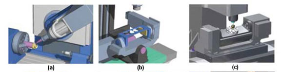
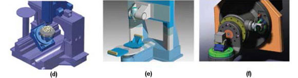
Figure 1: Typical arrangements of multi-axis CNC machines
- Head/Table: multi-axis machines execute the rotary motions with a table that carries the work piece. The spindle head articulates the tool with tilting motions (Figure 1(a), (f)).
- Table/Table: multi-axis machines execute the rotary motions with a dual rotary table. The primary rotary table carries the secondary rotary table, which in turn carries the fixture and the part (Figure 1(b), (c), (d)).
- Head/Head: multi-axis machines execute all rotary/pivoting motions by articulating the spindle head of the machine (Figure 1(e)).
Choosing a machine configuration depends on the type of product being manufactured. Important factors include the general work envelope needed, the spindle speed, and the weight of the parts being produced.
2.2 CAD/CAM systems
The applicable CAD/CAM systems are probably the most important aspect when considering 5-axis machining. The CAD (computer-aided design) and CAM (computer-aided manufacturing) modules are often referred to as a combined system, as many of these packages offer both CAD and CAM capabilities. However, it may be argued that very few systems excel equally in both.
Certain shops in the mould and die industry use CAM systems that have virtually no CAD capability, but they can import large, complex, multi-surface files quickly. It is then easy simply to choose the right cutting tools and select one of many automated cutting strategies. A tool path is generated and post-processed quickly, ready to use on the machine. However, when engineering changes need to be made, these changes often need to be made in a separate CAD package, and then imported back into the CAM software.
Another important feature of a high-end CAM system is to change the feed rate dynamically throughout the cutting process. This is very important in tool and die making where large amounts of material need to be removed. The topography of multi-surface moulds is often very complex, and it can be difficult to maintain a constant step-over, or even a constant depth of cut. Therefore the cutting forces on the tool vary greatly throughout the machining process. With a CAM system function such as feed rate optimisation, the software will vary the rate automatically. This takes place within the software before any cutting takes place, and is based on constants for volume removal rate, chip load, surface speed, and other factors. Feed rate optimisation produces constant cutting forces that lengthen tool life, increase accuracy, and dramatically shorten manufacturing costs.
Simulation is another important feature of a high-end CAM system when considering multi-axis work. This includes simulation of the cutting strategy, as well as simulation of the actual movements on the machine. The movements of the machine must be checked for possible collisions or gouging before any cutting takes place. The simulation should be able to show collisions between the machine, work piece, fixtures, cutting tools, and tool holders to ensure the safety of the process. A high-end CAM system should have the following tools to ensure this [12]:
- Cut pattern control
It is important to have more than one way to control the pattern that will be followed by a cutting tool. These patterns can be anything from a simple wireframe to complex surface patterns. Figure 2(a) shows how the cutting tool can conform to the irregular geometry of the part.
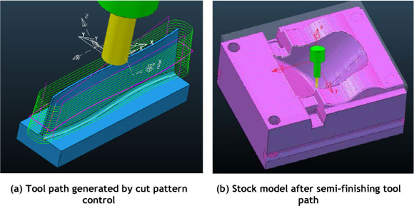
Figure 2: Typical high-end CAM system features
- Tool axis control
Through tool axis control, the centre axis alignment of the tool can be set and manipulated during the cutting process.
- Tool tip control
The tool tip control targets the precise area of the tool tip's engagement with the part.
- Collision avoidance
When 5-axis tool paths are being generated, special attention must be given to avoid any collisions, especially between the cutter, arbour, tool holder, and the work piece fixture assembly. Any collisions between moving components must be avoided when generating tool paths with 5-axis movements.
- Stock recognition
This feature will save a lot of time during 5-axis tool paths. This is the ability of the software to detect the initial stock size of a part or after a tool path has been cut. Figure 2(b) illustrates this.
- Post processor
Post processing is vital. It generates the code that drives the movements of the axes on the CNC machine so that the part can be machined. The native CAM language must be translated to match a machine's specifications. It is essential to know how the post processor works, especially when machining in 5 axes.
2.3 Tool holding systems and cutting tools
To achieve the desired results from 5-axis machining, the machine and CAM software are important, as are the actual cutting tools and holders. One would rarely see anything other than solid carbide being used as a cutting tool material on a 5-axis machine. Only with these tools can the possible high feed rates and spindle speeds be used. The tool must both withstand the high temperatures created during the milling process, and deliver the desired surface finish and accuracy that is vital in tool and die making. Cutting tools can have various types of coatings to support the process further. These coatings increase tool life, and allow for the machining of a wide range of materials such as tool steels, hardened tool steels, and titanium or nickel based super alloys.
Tool holding systems also play a huge role in 5-axis machining applications. Machines can achieve spindle speeds of up to 50,000 rpm, and require the tool holding system to be very accurate. This means tool holders must be precisely balanced to prevent any run-out accuracy of the cutting tool. This will directly influence the result of the 5-axis machining strategy. Of course, with 5-axis machining shorter tools can be used, as the part or the tool can be tilted into the right orientation to access certain features. However, there are sometimes limitations. Often one needs a slender tool extension to access deeper lying-features. Tool clamping systems - shrink fit and polygonal clamping - are some ways in which this can be solved (Figure 3). These types of tool holding systems provide the best possible accuracy with a deviation of only 0.003 mm.
Figure 3: Polygonal clamping system
3. CHALLENGES FOR THE SOUTH AFRICAN TOOLING INDUSTRY
In 2005, the results from a FRIDGE study confirmed the status of the South African tool and die manufacturing (TDM) industry as a key support component of the manufacturing sector. However, the research also found that the TDM industry is not currently well-positioned to take advantage of the growth opportunities available to it, but that it has the possibility of adapting efficiently and effectively if an industry master plan is adopted by all stakeholders and implemented thoroughly over the next ten years.
The SA manufacturing sector on average procures more than R6 billion of tooling annually. The SA TDM sector has declined over the last 20 years from a position of 80% to now less than 20% local supply [13]. The international consumption of tooling amounts to €64 billion per annum. Manufacturing represents 16-17% of SA's GDP, making it a key focus area of the Department of Trade and Industry's (DTI) industrial policy action plan (IPAP) to develop sustainable jobs through manufacturing localisation [13].
The national tooling initiative (NTI), a partnership between industry and government, is the turnaround intervention programme aimed at the rehabilitation and growth of the TDM sector, and has been identified by the DTI as a key programme to support the development of SA manufacturing competitiveness as the stimulus for sustainable economic growth and job creation. In this context, the Institute for Advanced Tooling (IAT) is involved in improving these conditions, and its main objective is to increase the competitiveness in the SA tooling industry by increasing the toolmakers' share in the total added value chain, measurable in added value per employee per hour. The aim is to change tool manufacturing from a resource-driven process to a knowledge-driven one, by offering a well-balanced combination of technology enablers for all steps of the extended life cycle to SMEs in the tooling sector. By facilitating the training of individuals through internships in the use of advanced technologies such as 5-axis high-speed machining, the IAT endeavours to help in the development of the SA tooling industry.
4. CASE STUDIES
In order to emphasise some of the benefits available in using 5-axis HSC, the following case studies from industry-related work are presented. In each case the Hermle C40U dynamic HSC milling centre was used. The CAM programming was done using Delcam's PowerMILL.
4.1 5-axis machining of deep cavity and tall core for injection mould
In this example, the final machining of a cavity, core, and core holder plate was done to produce a mould for a visor mask. Due to the large depth of the cavity and the required surface finish of the final moulded part, 5-axis cutting strategies were used. It would be possible to use a 3-axis CNC machine, but long small-diameter tools would then need to be used [14]. The depth of the cavity is almost 200 mm, and the shape within the cavity has small corner radius sections up to 3mm. To machine this using a 3-axis machine, a very long ball nose-type cutter would be needed to finish the radius sections. To use a 6mm diameter ball nose with a neck length of 200 mm would simply not work. The feed rate would be incredibly slow, and the tool would chatter so much that it would more than likely snap off [14]. Using a 5-axis cutting strategy from Delcam's PowerMILL software known as 'from point', the radius could be machined with a very short rigid tool. The machine axes simply tilt away to prevent any collision. High-feed rates could be used up to 3,000 mm/min and a spindle speed of 18,000 rpm. The result is an accurate radius area with a very smooth surface finish.
The same strategy was applied to the machining of the main cavity area. Again, a very long tool would be needed to machine the large depth of the cavity. The feed rate would have to be slowed down considerably to prevent tool chatter or breakage. Using a 'from point' strategy as before, a short series 10 mm ball nose-type cutter was used. A feed rate of 3,000 mm/min and a spindle speed of 16,000 rpm were used, which rendered a very smooth surface finish. Though some final polishing was still needed, the time required for this was drastically reduced due to the good post-machining surface finish obtained. If a 3-axis machine was used for this part, the operation time would be around three times longer, with a substantial reduction in surface finish quality that would make further polishing necessary. In addition, an electrode would be needed to finish the radius areas within the cavity. These additional steps would all add to the cost and time needed to produce the final part. Similar tools and strategies were used for the core section and core holder plate. Figure 4 below illustrates the 5-axis machining of (a) the CAM simulation strategy, and (b) the actual machining of the cavity section. Figure 5 shows the core holder plate, and reveals the quality of the surface finishes obtained.
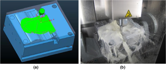
Figure 4: CAM simulation and 5-axis machining of visor mould cavity section
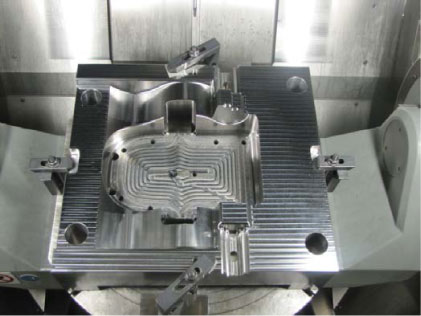
Figure 5: The core holder plate
4.2 5-axis machining of a routing fixture used in the aerospace industry
In this example, the client needed a fast turnaround on the routing fixtures. It consisted of a part and its mirror image. The part was already roughed-out using a 3-axis CNC machine. However, there were certain features such as grooves, profiles, and holes at various angles that could not be machined on a 3-axis machine. The grooves and profiles have undercut regions. The only way to machine this on a 3-axis machine would be to tilt the work piece into various orientations, requiring a fixture of some sort. This would add massive time to the production process and, of course, extra cost to manufacture the fixture. Even then a lot of the accuracy would be lost, and this could lead to mismatches between features. Another issue is the various holes along the whole shape of the top main surface. These holes are all at different angles and perpendicular to the shape of the surface at that point. To do this on a 3-axis machine would mean the part being oriented into various positions. With 35 holes altogether, the part would need to be rotated and orientated 35 times just to do each hole individually. This would be a very time-consuming process. Again, the accuracy could not be guaranteed. Figure 6 shows the 3D model with all the problematic features and holes at different angles.
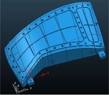
Figure 6: 3D CAD model of routing fixture
Using the Hermle 5-axis machining centre and Delcam's PowerMILL, the routing fixture could be machined in a single setup. Through an automatic recognition of a hole within the CAM software, all the holes were centre-drilled and drilled in one setup. All the different orientations of holes were referenced to a single work plane, which improved the overall machined accuracy. Furthermore, the grooves and undercut regions could be machined using an automatic swarf-milling strategy. This aligns the tool automatically to the selected geometry during the cutting process. Using the 5-axis machine, the routing fixtures were machine-finished within 3 days. Again this is a huge saving in time and cost. Figure 7 below shows (a) the detail of the actual routing fixture indicating an undercut region and the achieved surface finish, and (b) the part size in reference to the machine bed.
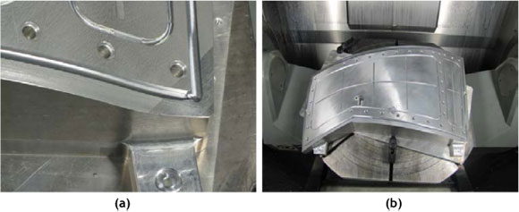
Figure 7: Routing fixture for an aerospace component
5. CONCLUSIONS AND RECOMMENDATIONS
The challenges that face the South African TDM industry are indeed many, especially in the context of growing international competition and a decline in skilled labour. However, with the increasing availability of advanced manufacturing technologies such as 5-axis simultaneous high-speed machining, in combination with initiatives to invest in human capital and training to re-establish a high level of skilled labour, these challenges can be overcome. This article highlights a number of these challenges, and attempts to emphasise some of the benefits that can be obtained from using 5-axis HSC strategies rather than conventional 3-axis machining. Though this technology may seem very expensive at first, the benefits in improving productivity would eventually far outweigh the current time-consuming conventional methods widely employed in the industry.
REFERENCES
[1] Bernard, A. & Fischer, A. 2002. New trends in rapid product development, Keynote Paper, CIRP-General Assembly, San Sebastian. [ Links ]
[2] Dietrich, J. & Kochan, D. 2004. Rapid manufacturing by HSC (High Speed Cutting), Proceedings, International Conference on Competitive Manufacturing, COMA '04, Stellenbosch, South Africa. [ Links ]
[3] Lauwers, B., Kswanto, G. & Kruth, J.-P. 2005. Development of a five-axis milling tool path generation algorithm based on faceted models, Annals of the CIRP, 54(2). [ Links ]
[4] Klocke, F., Markworth, L. & Borsdorf, B. 2001. High performance machining of aerospace components, Proceedings, International Conference on Competitive Manufacturing, COMA '01, Stellenbosch, South Africa. [ Links ]
[5] Altintas, Y. & Merdol, D.S. 2007. Virtual high performance milling, Annals of the CIRP, 56(2). [ Links ]
[6] Takino, H., Kawai, T. & Takeuchi, Y. 2007. 5-axis control ultra-precision machining of complex- shaped mirrors for extreme ultraviolet lithography system, Annals of the CIRP, 56(2). [ Links ]
[7] Garcia, J.P. & De Carvalho, J. 2005. Rapid manufacturing - An evaluation of rapid prototyping and HSC technologies in product development, Proceedings, 2nd International Conference on Advanced Research in Virtual and Rapid Prototyping, Leiria, Portugal. [ Links ]
[8] Bergs, T. 2004. Technology trends and perspectives in die and mould making, Proceedings, International Conference on Competitive Manufacturing, COMA '04, Stellenbosch, South Africa. [ Links ]
[9] Oosthuizen, G.A., Akdogan, G., Dimitrov, D.M. & Treunicht N.F. 2010. A review of the machinability of titanium alloys, R & D Journal of the SAIMechE, 26, 43-52. [ Links ]
[10] Dimitrov, D.M., Neugebauer, R., Oosthuizen, G., Schmidt, G., Treurnicht, N. & Blaine, D. 2010. High performance machining of selected titanium alloys for aerospace applications, Proceedings, ICMC, Sustainable Production for Resource Efficiency and Ecomobility, Chemnitz. [ Links ]
[11] Dimitrov, D.M., Saxer, M. & Treurnicht, N. 2010. Evaluation and selection of cutting strategies in high performance machining of titanium on the example of aerospace components, Proceedings, Light Metal Conference, Johannesburg. [ Links ]
[12] Apro, K. 2008, Secrets of 5-axis machining, Industrial Press, New York. [ Links ]
[13] National Tooling Initiative Programme, n.d. Overview, accessed 30 August 2011 at http://www.ntipweb.co.za/index_ntip.php. [ Links ]
[14] Hurco Companies, Inc. n.d. Five axis machining, accessed 20 August 2011 at http://www.fiveaxismachining.com/index.php/welcome/. [ Links ]
* Corresponding author
# This article is an extended version of a paper presented at the 2011 RAPDASA conference.

