Servicios Personalizados
Articulo
 Inglés (pdf)
 Articulo en XML
 Referencias del artículo
Indicadores

Links relacionados
-
 Citado por Google
 -
 Similares en Google
Compartir

 Permalink
South African Journal of Industrial Engineering
versión On-line ISSN 2224-7890
versión impresa ISSN 1012-277X
S. Afr. J. Ind. Eng. vol.23 no.3 Pretoria ene. 2012
GENERAL ARTICLES
Assessment of surface finish and dimensional accuracy of tools manufactured by metal casting in rapid prototyping sand moulds#
K. NyembweI, *, 1; D.J. de BeerII, 1; J.G. van der WaltIII, 1; S. BheroIV, 1
IDepartment of Metallurgy University of Johannesburg, South Africa. dnyembwe@uj.ac.za
IITechnology and Transfer Innovation Vaal University of Technology, South Africa. deond@vut.ac.za
IIIDepartment of Mechanical Engineering and Applied Mathematics Central University of Technology, South Africa. jgvdwalt@cut.ac.za
IVDepartment of Metallurgy University of Johannesburg, South Africa. bshepherd@uj.ac.za
ABSTRACT
In this paper, an initial assessment of the quality parameters of the surface finish and dimensional accuracy of tools made by metal casting in rapid prototyping (RP) sand moulds is undertaken. A case study from a local tool room, dealing with the manufacturing of an aluminium die for the lost wax process, is employed. Modern techniques, including surface roughness analysis and three dimensional scanning, are used to determine and understand how each manufacturing step influences the final quality of the cast tool. The best surface finish obtained for the cast die had arithmetic average roughness (Ra) and mean average roughness (Rz) respectively equal to 3.23µΓη and 11.38µΓη. In terms of dimensional accuracy, 82% of cast-die points coincided with the Computer Aided Design (CAD) data, which is within the typical tolerances of sand cast products. The investigation shows that mould coating contributes slightly to the improvement of the cast tool surface finish. The study also found that the additive manufacturing of the sand mould was the chief factor responsible for the loss of dimensional accuracy. These findings indicate that machining will always be required to improve the surface finish and the dimensional accuracy of cast tools in RP sand moulds.
OPSOMMING
In dié artikel word 'n aanvanklike beoordeling van kwaliteitsparameters in terme van oppervlak-afwerking en dimensionele akuraatheid van gietstukke vervaardig deur metaal gieting in snel-prototipering sand gietvorms gedoen. 'n Gevallestudie aangaande die vervaardiging van 'n aluminium gietstuk vir die verlore wasproses word gebruik. Moderne tegnieke, soos oppervlak-grofheidsanalise en drie-dimensionele skandering, word gebruik om te bepaal hoe elke vervaardigingstap die finale kwaliteit van die gietstuk beïnvloed. Die beste oppervlak afwerking verkry vir die gietstuk het Ra en Rz waardes van 3.23 µπι en 11.38 µΓη onderskeidelik gehad. In terme van dimensionele akkuraatheid, het 82% van die gietvormpunte ooreengestem met die rekenaarnumeriesbeheerde data wat binne tipiese toleransies is vir sandgegote produkte. Die ondersoek wys dat gietvorm oppervakbedekking effens bydra tot die verbetering van die gietstukafwerking. Ook is gevind dat die snel-prototiperingvervaardigingsproses van die sandgietvorm die hooffoorsaak is vir die verlies aan dimensionele akkuraatheid. Dié bevindings dui aan dat masjinering altyd nodig sal wees om die oppervlak-afwerking en dimensionele akkuraatheid te verbeter.
1. INTRODUCTION
Rapid prototyping (RP) or additive manufacturing processes for the fabrication of sand moulds include laser sintering (LS) and three dimensional printing (3DP) [1]. In LS, resin-coated sand grains are sintered together by the heat generated by a laser beam. 3DP technology, on the other hand, makes use of selective deposition of foundry resin on sand grains to achieve their agglomeration into solid parts. In both systems, post-treatment of the mould is required to obtain optimal strength of the parts. This is achieved by curing the mould in a furnace. The two RP systems locally available in South Africa are the Direct Croning Casting Process (DCCP) based on LS, and the Z-Cast process based on 3DP [2].
RP processes for sand moulds do not require time consuming and costly pattern making. They are therefore extensively employed, especially in the automotive foundry industry, to produce casting prototypes used for design and metallurgical evaluation prior to mass production. RP processes decrease the lead casting design time and accelerate the introduction of new components.
Recent technological developments of these RP processes include quick manufacturing time with the advent on the market of large machines capable of producing several moulds in a few hours. The S Max machine from ExOne Company is an example of such equipment based on 3DP [3]. Another modern trend is the use of RP sand moulds to manufacture aerospace components. This is already happening locally with the production of the Adept light craft engine block from laser sintered moulds [4]. Internationally, Prometal-RCT recently signed an agreement with Fonderie Messier, a French aluminium and magnesium foundry, to produce casting parts for aerospace applications in RP sand moulds [5].
Considering the above applications, some researchers have gone one step further and proposed the manufacturing of metallic tooling by casting in RP sand moulds. This alternative tool-making process is referred to as rapid casting for tooling (RCT) [6]. It is a contribution to the ongoing search for improved and innovative tool manufacturing processes to meet the stringent customer requirements of quality and economics [7, 8]. RCT is an addition to the plethora of indirect rapid tooling methods that have continued to be developed and diversified since their emergence in the last 15 to 20 years [9].
RCT essentially has five steps: computer assisted design (CAD), casting simulation, RP, casting, and finishing operations (Figure 1). The authors have claimed that, compared with traditional tool-making processes such as machining and existing rapid tooling, it offers potential advantages: near net shape, quick manufacturing time, and low production cost.
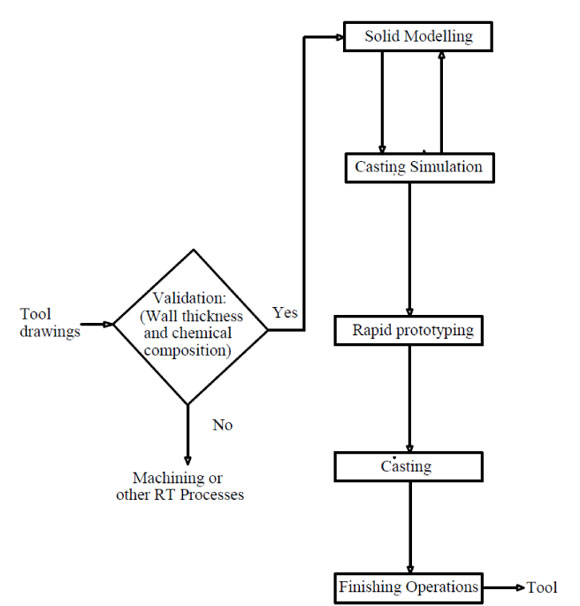
Figure 1: RCT process chain [3]
In a theoretical study comparing locally-available RP processes using the analytical hierarchy process (AHP) technique, it was found that DCCP is more suitable than the Z-Cast process when applied to RCT [10]. According to this study, tools obtained from DCCP moulds would have the best surface finish and dimensional accuracy. On the other hand, tools produced from the Z-Cast process would be cost-efficient and quick to produce. The study was based on the results of several benchmarking studies [11,12,13,14] in which parts from various RP processes were compared using characteristics such as surface finish, dimensional accuracy, manufacturing time, and cost.
However, at present it is not known how RCT tools will score in practice, based on these tool characteristics. It is also important to investigate the effects of the various RCT steps on these characteristics. In this paper, only the surface finish and dimensional accuracy of RCT tools are examined, using a case study. These tool characteristics are among the most crucial regarding tool usability.
2. METHODOLOGY
The study methodology consists of three elements:
- The manufacturing of tools by casting in RP sand moulds
- The measurement of the mould and tool surface finish
- The assessment of the mould and tool dimensional accuracy
2.1 Manufacturing of tools by casting in rapid prototyping sand moulds
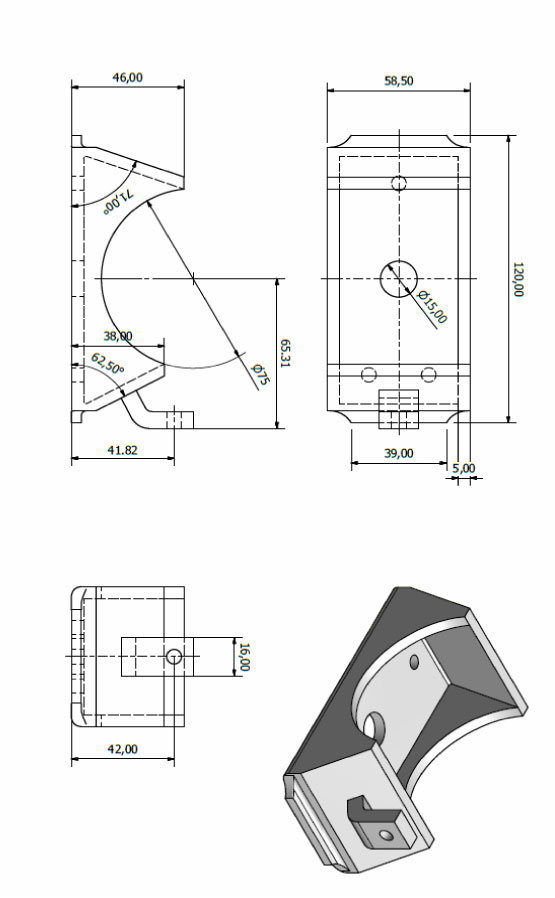
The tool manufactured in this investigation was an aluminium die for the production of wax patterns used in the investment casting of a steel bracket. The 2D drawings of this steel component are shown in Appendix 1. The die parts were produced following the RCT process chain, shown in Figure 1. The casting modelling of sand moulds was done using Pro-Engineering software. A snapshot of the 3D model of the bottom part of the die is shown in Figure 2(a). Casting simulation using Magmasoft software was conducted, ensuring that the mould would be filled without turbulence and the die would solidify without detrimental shrinkage porosity. A top gating system through a Foseco Kalpur device was used. An EOSINT S 700 RP machine was used to grow the sand mould for cast dies shown in Figure 2(b). This machine is based on LS of foundry sand. One of the sand moulds produced was brush coated with Foseco's ISOMOL 185. ISOMOL coatings are flammable, solvent-based mold and core coatings. The principle refractory medium contained in these coatings is a high-purity zircon. ISOMOL coatings are recommended for use in the casting of iron, steel, and non-ferrous alloys - including aluminium alloys. These coatings can be used through a wide range of metal casting sections. ISOMOL coatings provide excellent casting surface quality [15]. Gravity casting was used to produce the final tool. Aluminium silicon alloy (LM4) was melted in an electric furnace at 7500 C and the liquid metal degassed prior to casting. The final cast die components are shown in Figure 2(c).
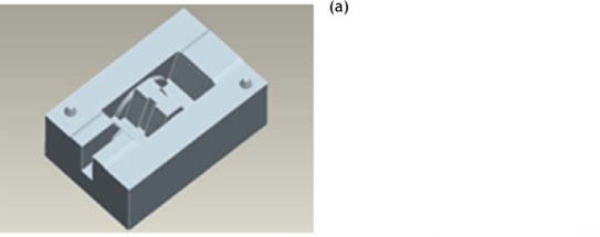
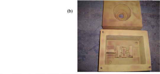
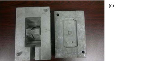
Figure 2: (a) CAD of the lower part of the die; (b) DCP mould; (c) RCT die - cast before finishing operations
2.2 Measurement of the mould and tool surface roughness
The surface finish or surface roughness was determined using a portable surface roughness tester (TIME model TR 110). This instrument provides two roughness parameters, the arithmetic average roughness (Ra) and the mean average roughness (Rz), that characterise the surface profile of the mould and casting. Ra reflects the average height of roughness component irregularities from a mean line. Rz, on the other hand, is the average distance between the highest peak and the deepest valley in five sampling lengths or cutoffs. Rz is generally more sensitive than Ra to changes in surface finish, because maximum profile heights, and not the averages, are examined. Schematic representations of Ra and Rz are shown in Figure 3. The mould surface roughness was obtained as the average of the surface roughness of 18 points, shown in Figure 4. Corresponding points on the cast die were considered to determine its overall surface finish.
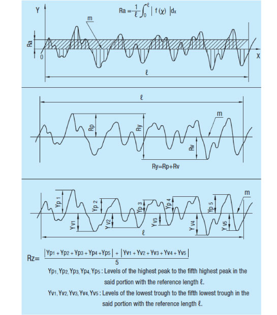
Figure 3: Variety of surface roughness indicators and typical calculations [16]
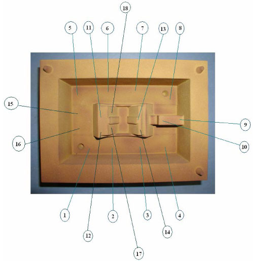
Figure 4: Points used to determine average surface roughness of the mould
Surface roughness was measured for the following objects:
- Uncoated RP mould
- Coated RP mould
- Casting produced from uncoated mould
- Casting produced from coated mould
2.3 Assessment of the mould and tool dimensional accuracy
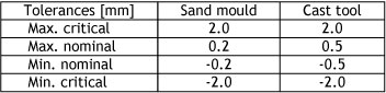
A two-step process, shown in Figure 5, was followed to measure and assess the dimensional accuracy of moulds and cast tools. A VIVID 910 3D non-contact digitizer from Konica Minolta was used to produce the 3D scanned data from the parts. The 3D scanned data were then compared to the original CAD data during the merging step using Geomagic Qualify software. Dimensional accuracy results consist of 3D comparison and deviation distribution of dimensions. Table 1 shows the dimensional tolerances used for the merging of sand moulds and castings. These tolerances have been informed by the literature that reports on the dimensional accuracy of LS and shell casting processes [11,17].
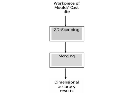
Figure 5: Process flow diagram for the assessment of dimensional accuracy
Table 1: Tolerances used in the merging process
The dimensional accuracy was determined for the following objects:
- Uncoated RP mould
- Coated RP mould
- Casting produced from uncoated mould
3. RESULTS
3.1 Surface roughness
Figure 6 shows the average values of surface roughness for the various parts. The coated mould has a better surface finish than the uncoated mould. The difference in roughness is important, as the Ra and Rz parameters of the uncoated mould are 2.5 and 1.8 times larger respectively than the same parameters for the coated mould. On the other hand, the RCT tool obtained from the coated mould has an overall smoother surface finish than the cast tool produced from the uncoated mould. The best surface finish obtained for the cast die had an Ra of 3.23µΓη and an Rz of 11.38µm.
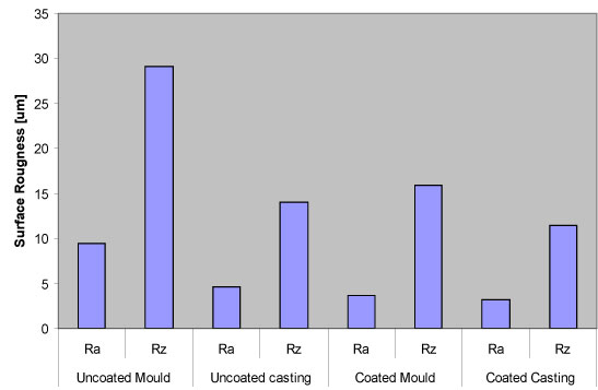
Figure 6: Average roughness for the RP moulds and the RCT tool
3.2 Dimensional accuracy
3.2.1 3D comparison
The 3D comparisons of the scanned data with the original reference CAD data are shown in Figure 7. The green areas represent points that have dimensions within the nominal tolerances defined in Table 2. The blue areas represent points that have dimensions below those of the reference part. The yellow and red areas represent points with dimensions above those of the reference part. It appears that the coated mould has a better overall accuracy than the uncoated mould, and than the cast die from the coated mould.
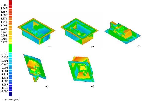
Figure 7: 3D comparison of scanned parts with original CAD data: (a) uncoated mould (b) coated mould (c) coated casting (d) coated casting vs coated mould (e) coated mould vs uncoated mould
Figure 8 represents the quantified geometric and dimensional accuracy obtained after merging. An accuracy of 82% was achieved for the cast die within the nominal tolerances of ±0.5mm. The coated mould appears to exhibit a better accuracy than the uncoated mould, with 90% point clouds coinciding with the original CAD data within an error range of ±0.2mm in the former case, compared with 82% in the latter case.
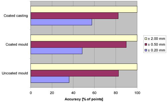
Figure 8: Geometric and dimensional accuracy of RP moulds and cast die
3.2.2 Deviation distribution of dimensions
The deviation distribution graphs from the comparison of scanned data with the reference CAD data are shown in Figures 9(a), 9(b), and 9(c). On the other hand, Figure 10(a) and 10(b) reveal the comparison of the coated mould scanned data with the cast die, and with the uncoated mould. The following general observations can be made from these graphs:
- Data are missing in the central part of the graphs;
- 70% to 80% of the points lie on the right hand side of the graphs; and
- a pattern emerges as one progresses from Figure 9(a) to Figure 9(c). The left-hand side bars are continuously truncated, while the right-hand bars increase in height.
4. DISCUSSION
4.1 Surface finish
The coated mould exhibits a better surface finish than the uncoated mould (Figure 6). This is due to the coating product that was applied before casting, filling the interstices of the uncoated mould's surface created by the granular structure of the sand grains, and the layer-by-layer manufacturing of the mould. This improvement in surface finish due to the coating is transferred to the cast tool. The RCT tool produced from the coated mould has an overall better surface finish than the one produced from an uncoated mould. However, the difference of tool surface roughness between the casting from the uncoated mould and the one from the coated mould is not very significant - the Ra and Rz parameters are close. Possible reasons include the particle size of the moulding sand, the pouring temperature of the cast alloy, and the wetting properties of the aluminium silicon alloy.
The LS process for the sand mould is similar to the Shell sand process, characterised by the use of very fine sand with an AFS number higher than 60 in order to improve the surface finish of a casting [18]. It appears that in this instance, the application of a coating has a reduced effect in improving the casting surface finish. The other possible reason is the relatively low pouring temperature (7500C) of the cast alloy in this investigation, compared with the sintering temperature of silica sand (14500C) [19]. At this temperature, it is unlikely that any sand burn defect can occur, which explains the limited effect of the coating in improving the surface finish. Finally, if the alloy does not wet the mould surface sufficiently, its irregularities will not be transmitted to the casting.
The average Ra and Rz for the cast tool produced from the coated mould were 3.23 and 11.38µΓη respectively. These values are still much higher than a machined part, with values of Ra between 1.6 and Ο.ΙµΓη [20]. This confirms the need to include additional machining in the final operational steps of the RCT diagram, so that the RCT tools meet the standard specification of tools for surface finish.
4.2 Dimensional accuracy
The application of a coating layer to the sand mould cavity seemed to have compensated for the errors of the uncoated mould, thus making the coated mould appear to have a better overall geometric and dimensional accuracy. Considering the RCT steps, the most probable source of the dimensional errors in the uncoated mould would be the AM step by laser sintering. This step involves the layer-by-layer growing of the mould, followed by its strengthening by curing in an oven at 2200C for 200 minutes. It is possible that mould expansion and deformation occur during curing. This phenomenon, evident with the larger RP mould, still has be fully investigated.
On the other hand, the cast die seemed to have lost the dimensional accuracy of the coated sand mould, as shown in Figure 8. Figures 7(c) and 9(c) suggest that the cast die has expanded in terms of dimensions. This expansion could be attributed to mould wall movement during the casting step. The displacement of sand mould walls is generally caused by the metallo-static pressure on those walls by the molten metal entering the mould cavity. Factors such as the low strength of the mould, or the loose closing of the mould, accentuate the mould wall movements such that the expansion of the casting might possibly surpasses the contraction associated with the casting solidification, resulting in a loss of dimensional accuracy. Figures 7(e) and 10(b) corroborate the explanation of possible mould wall movement during casting.
Two phenomena - sagging during mould curing, and mould wall movement during casting -could be determining the final dimensional accuracy of the RCT tools. It appears that the most important factor in the loss of dimensional accuracy was the RP step.
5. CONCLUSION
In this study, an initial assessment of the surface finish and dimensional accuracy of RCT tools was conducted. The investigation showed that mould coating contributes slightly to the improvement of the cast tool surface finish. With the dimensional accuracy of the cast tool, incremental contribution of the RP step and metal casting led to the final cast die being larger than that aimed for during the casting modelling. The biggest contributor to the loss of dimensional accuracy was the RP stage, possibly during the post treatment of the mould by curing in a furnace. Because of this, machining will always be required to improve the quality of RCT tools, particularly if they are to be used for mass production processes, for which there are stringent standards for the surface finish and the dimensional accuracy.
REFERENCES
[1] Lerner, Y., Rao, P.N. & Kouznetsov, V. 2002. Rapid tooling applications in metal casting, Foundry Management and Technology, pp. 47-55. [ Links ]
[2] Chua, C.K., Leong, K.F. & Lim, C.S. 2003. Rapid prototyping: Principle and applications, 2nd ed. Singapore: World Scientific Publishing. [ Links ]
[3] ExOne. 2012. S-Max. The ultimate in production flexibility and efficiency. http://www.exone.com/materialization/systems/S-Max (Accessed 22 July 2012). [ Links ]
[4] Adept. 2011. Rapid prototyping. http://www.adeptairmotive.com (Accessed 31 March 2011). [ Links ]
[5] Fonderie Messier. 2011. Fonderie Messier et Prometal RCT Signent un Accord de Partenariat Technologique. http://www.ventana-aerospace.com/upload/documentation/fichier/12-129-communique_de_presse_fm_prometal_rct.pdf (Accessed 22 July 2012). [ Links ]
[6] Nyembwe, K., De Beer, D. & Bhero, S. 2010. A conceptual framework for the manufacturing of tooling by metal casting in refractory moulds and shells produced by rapid prototyping, Proceedings of 24th Annual SAIIE Conference, Gauteng, pp. 160-171. [ Links ]
[7] Peres, F. & Mafokhami, A. 2001. Validation of product and process design by the use of a new rapid tooling process, Transactions of the SDPS, 5(2), pp. 23-37. [ Links ]
[8] Jiang, X., Liu, X. & Zhang, C. 2005. Feasibility study of a new rapid tooling process, International Journal of Advanced Manufacturing Technology, 27, pp. 296-304. [ Links ]
[9] Wholers, T. 2009. Wholers Report 2009. State of the industry worldwide progress report. Wholers Associates. [ Links ]
[10] Nyembwe, K., De Beer, D., Van Der Walt, J. & Bhero, S. 2011. A case study of additive manufacturing process selection for a casting application using the analytic hierarchy process, 115th MetalCasting Congress, Chicago, 11-019, pp. 1-8. [ Links ]
[11] Kim, G.D. & Oh, Y.T. 2008. A benchmark study on the rapid prototyping processes and machines: Quantitative comparisons of mechanical properties, accuracy, roughness, speed and material cost, Proc. IMechE, 222(B). [ Links ]
[12] Dimitrov, D., Van Wijck, W., Schereve, K. & De Beer, N. 2003. On the achievable accuracy of the three dimensional printing process for rapid prototyping, Proceedings of the 1st International Conference on the Advanced Research in Virtual and Rapid Prototyping, pp. 575-582. [ Links ]
[13] Dimitrov, D., De Beer, N., De Beer, D. & Erfort, E. 2005. A comparative study between capability profiles of RP processes with a focus on 3D-printing, Metalworking News, 4(1), pp. 5766. [ Links ]
[14] Pham, D.T. & Gault, R.S. 1998. A comparison of rapid prototyping technologies, International Journal of Machine Tools & Manufacture, 38, pp. 1257-1287. [ Links ]
[15] Foseco. 2005. Sand Mold and Core Coatings. http://www.fosecomet.com/index.php?option=com_content&task=view&id=107&Itemid=15 (Accessed 23 October 2011). [ Links ]
[16] JISB0031. 1994. Technical Data Surface Roughness. http://www.misumiusa.com/CategoryImages/Metric_2009_pdf/p2839.pdf (Accessed 16 August 2011). [ Links ]
[17] Groover, M.P. 2006. Fundamentals of modern manufacturing: Materials, processes, and systems, 3rd ed., Wiley. [ Links ] nd
[18] Beeley, P. 2001. Foundry technsology, 2nd ed. Butterworth-Heinemann. [ Links ]
[19] Brown, J.R. 1999. Foseco Non-ferrous Foundryman's Handbook, 11th ed., Oxford, Butterworth-Heinemann. [ Links ]
[20] Degarmo, E.P., Black, J.T. & Kohser, R.A. 2003. Materials and processes in manufacturing , 9th ed., Wiley. [ Links ]
* Corresponding author.
# This article is an extended version of a paper presented at the 2011 RAPDASA conference
1 The author is enrolled for a D Tech: Engineering: Mechanical degree in the Department of Mechanical Engineering and Applied Mathematics, Central University of Technology.
Appendix 1: 2D drawings of steel bracket