


Servicios Personalizados
Articulo
 Inglés (pdf)
 Articulo en XML
 Referencias del artículo
Indicadores

Links relacionados
-
 Citado por Google
 -
 Similares en Google
Compartir

 Permalink
South African Journal of Industrial Engineering
versión On-line ISSN 2224-7890
versión impresa ISSN 1012-277X
S. Afr. J. Ind. Eng. vol.23 no.3 Pretoria ene. 2012
GENERAL ARTICLES
Residual stress measurements and structural integrity implications for selective laser melted Ti-6Al-4V#
C.R. KnowlesI, *, 1; T.H. BeckerII, 1; R.B. TaitIII, 1
IDepartment of Mechanical Engineering University of Cape Town, South Africa. craig.knowles@uct.ac.za
IIDepartment of Mechanical Engineering University of Cape Town, South Africa. thorsten.becker@uct.ac.za
IIIDepartment of Mechanical Engineering University of Cape Town, South Africa. robert.tait@uct.ac.za
ABSTRACT
Selective laser melting (SLM) of Ti-6Al-4V has significant potential in the aerospace and biotechnology industries. SLM employs a focused laser beam to melt successive layers of metallic powder into complex components. This process can result in the generation of high thermally-induced residual stresses. These residual stresses, together with micro-flaws/ pores from the inherent fabrication process, may lead to premature fatigue crack initiation and propagation at relatively low cyclic stresses. The hole-drilling strain gauge method was used to evaluate residual stresses within SLM Ti-6Al-4V specimens, with the intention of understanding the associated mechanisms for the successful application of SLM Ti-6Al-4V in industry.
OPSOMMING
'Selective laser melting' (SLM) van Ti-6Al-4V het aansienlike potentiaal in die lugvaart en biotegnologiese bedrywe. SLM maak gebruik van 'n gekonsentreerde laser straal om agtereenvolgende lae metaal poeier te smelt en sodoende intrieke metal komponente te vorm. Gedurende SLM kan hoë resterende spanning veroorsaak word as gevolg van hoë temperature. Hierdie spanning, asook mikrodefekte wat gedurende die vormingsproses ontstaan, mag lei tot voortydige materiaalverswakking deur spleet vorming en verspreiding gedurende betreklik lae sikliese spannings. Resterende spanning in Ti-6Al-4V eksemplare is bereken deur 'n boor-versonke rekstrokie metode om sodoende die meganismes verantwoordelik vir die suksessvolle toepassing van SLM in die Ti-6Al-4V bedryf te bepaal.
1. INTRODUCTION
The additive manufacturing technique known as selective laser sintering (SLS) was developed by Carl Deckard for the plastics industry in 1987 [1]. Since then it has been adapted for metallic materials, for which the term selective laser melting (SLM) has been derived. This is due to the relatively higher manufacturing temperatures required in SLM [2]. SLM allows for the manufacturing of geometrically complex components. It has the ability to produce an almost fully-dense material, with comparable properties to those of the bulk material, while avoiding lengthy machining times and post-processing cycles [3]. The technique is therefore very attractive for the aerospace, automotive, and electronics industries, as well as in prosthetic biotechnology in which intricate designs are often required [4].
Recently the material capability of SLM has been extended to the Ti-6Al-4V alloy. This alloy is the most common commercial titanium alloy in production, and has been much used in the biomedical and aerospace industries [5]. Ti-6Al-4V was first developed in 1954 at the Illinois Institute of Technology in the United States of America [6]. The popularity of Ti-6Al-4V is primarily due to its excellent balance of properties: it has high strength and good toughness properties, in addition to being heat treatable, where the mechanical properties are heavily dependent on their complete processing history [7].
The SLM manufacturing process is illustrated in Figure 1a. A high energy focused laser beam is used to melt powder completely (in a powder bed), which subsequently bonds the new layer with the previously built layer (as shown in Figure 1a)[1]. One major drawback, however, is the high temperature gradients introduced by the manufacturing process. The melting process (through the use of the high energy laser beam) can result in thermal residual stresses, produced by the expansion and contraction of the previously solidified layers [8]. These stresses can exceed the yield strength of the material [9], and have been reported to initiate premature fracture of the component [9].

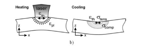
Figure 1: a) Transverse view of the selective laser melting process on both a rigid substrate base and loose powder [9]; b) temperature gradient mechanism (TGM) [8].
The mechanisms of residual stress in SLM-produced components are primarily due to the temperature gradient mechanism (TGM) and the cooling phase of the upper molten layers, as shown in Figure 1b. Previous studies of the residual stress profiles in SLM-produced components indicate that the stress gradients are dominated by two regions: one of a tensile stress in the upper portion of the part (with a maximum stress attained at the surface); and the other by an intermediate compressive stress in the region between the upper and lower surfaces (see Figure 1b) [8]. TGM occurs due to the underlying layers hindering the expansion of the upper layers (the material does not have to be molten for this to occur). In this event, the restriction of the expansion of the heated layer induces elastic compressive strain in the material. During the cooling mechanism, the upper molten layers shrink via thermal contraction (hindered by the lower solidified layers), resulting in a tensile stress in the upper layer and a compressive stress in the lower layer [8].
A major concern for SLM Ti-6Al-4V is the presence of residual stresses in components. These residual stresses, together with micro-flaws and pores from the inherent fabrication process, may lead to premature failure of components [10]. From a fracture mechanics perspective, residual stress may facilitate premature fatigue crack initiation sites and propagation at relatively low cyclic stresses [11]. The aim of this paper is to investigate such residual stresses and the consequent implications for material performance.
2. METHODOLOGY
The experimental procedures used to evaluate the residual stresses present in the SLM-manufactured Ti-6Al-4V and the investigation of the respective material performance used the following techniques: density measurements using the 'Archimedes-method' according to MPIF Standard 54, together with an optical verification process; the hole drilling method for determining residual stresses (ASTM standard test method E 837); and a microscopy evaluation of the microstructure.
2.1 Specimen details
The SLM Ti-6Al-4V specimens supplied by the Centre for Rapid Prototyping and Manufacturing (CRPM) at the Central University of Technology consisted of two tensile test specimens. These specimens, manufactured on an EOSINT M270 SLM machine, were initially intended for tensile testing. However, on removal from the manufacturing base plate, they presented excessive deformations, which initiated the need for residual stress investigations. This deformation was believed to have been caused by high residual stresses that were partially relaxed during removal of the component. These specimens are shown in Figure 2a below, with a CAD schematic illustrating the part detail in Figure 2b. The deformation observed during the component removal is shown in the plan view of the specimen base in Figure 2c.
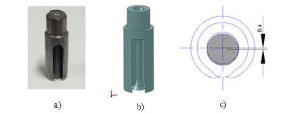
Figure 2: a) An SLM specimen received for residual stress testing; b) CAD schematic of the specimen detail; and c) a plan view of the specimen base and the observed deformation.
2.2 Density test
The density of the specimens was measured according to MPIF Standard 54 (for impermeable powder metallurgy materials), which is based on the principle of the 'Archimedes-method', i.e. water displacement [12]. To do this, longitudinal and cross-section pieces were cut from the specimens and polished so that no air bubbles would cling to the surface roughness. The sections were weighed in air, then weighed when immersed in distilled water. The specimen density ρ was calculated according to equation (1).

where A is the mass of the specimen in air, B is the apparent mass of the specimen and its support in water, C is the mass of the specimen support in water, and pw is the density of water.
The density results were verified using an optical methodology where high definition micrographs were analysed for their pixel intensity. In this method, the pixel intensity (i.e. grey level) is used to determine the porosity in a specimen section. The pixel range in a micrograph is between 0 (darkest) and 255 (lightest). The threshold for a void was set at a pixel value of 70, below which all pixel values were considered to be voids or pores. This threshold was tested for pixel values between 50 and 90, with negligible change in the result observed. It is worth noting that this methodology is limited, as it measures density from an area perspective. It does, however, provide a good verification tool.
2.3 Residual stress measurement
Measurements of the residual stress in an opaque material (such as a metal) require the locked-in stress to be relieved so that the sensor mechanism is able to register the strain change [13]. This is accomplished by the removal of material through a drilled hole. The hole is unable to carry any stress, so the strains around the hole must change to accommodate this change in the stress state. This strain-change is then related to the stress state through a series of equations. This hole drilling method for determining residual stresses is standardised in the ASTM standard test method E 837-08 [14].
The drilling rig used in this work was a micro-measurements RS-200 optical drilling system with an air-turbine high speed drill attachment for drilling accuracies to within 0.038mm [13]. The instrumentation consisted of a measurements group P-3500 strain indicator and an Sb-10 switch and balance unit. A fan is positioned to cool the specimen during the drilling process to ensure strain readings are not hampered by temperature fluctuations. The experimental rig is shown in Figure 3. The strain gauges used in this study were Micro-Measurements CEA-06-062UM-120 rosettes, as shown in Figure 4. On each specimen, two strain gauges were used, with one positioned on the outer support shell, and another on the small diameter end cap (Figure 4). An experimental overview of the method is given below:

Figure 3: Experimental setup for residual stress measurements

Figure 4: Position of strain gauge rosettes on the large diameter shell (sector B) and the small diameter end cap (sector A). Note that the strain gauges are orientated horizontally on the specimen as shown above.
- A strain gauge (three element) rosette is positioned and fixed to the specimen, then connected to a multi-channel static strain-measuring indicator.
- A precision drilling platform (RS-200 milling guide) is positioned around the specimen so that the drill piece is centred exactly on the strain gauge rosette centre.
- The strain is registered at incremental depths of the hole so that the residual stress change with depth can be determined.
- Data reduction relationships are used to determine the orientation and magnitude of the principal stresses.
2.4 Microstructure evaluation
Specimens were cut in the longitudinal and transverse directions so that the microstructure, porosity, or discontinuities could be observed in both the 'in build' direction and the 'in the plane' direction (perpendicular to the 'in build'). The specimens were polished and etched using a solution of hydrogen peroxide, hydrofluoric acid, and nitric acid to examine the grain structure [15].
3. EXPERIMENTAL RESULTS
The experimental tests were conducted on two large specimens (shown in Figure 2), machined and polished into the dimensions specifically required by the test. All tests were conducted in ambient conditions in the materials laboratory at the University of Cape Town.
3.1. Density measurements
In a theoretically-100% dense wrought Ti-6-Al-4V, the 'Archimedes-method' density tests on the SLM Ti-6Al-4V yielded an average density of 99.75%, and the optical density verification (through pixel analysis) yielded an average density of 99.7%. These density tests demonstrate the capability of SLM to produce nearly fully-dense components. The-micrographs of the polished, unetched specimens revealed several micro-flaws and voids in the material, in addition to surface roughness defects. The shape and size of these flaws vary between sharp-edged defects (Figure 5a) and near circular voids (Figure 5b). The micro-flaws and defects near the surface of the specimen are shown in Figures 5c and d. These defects and pores are most likely attributable to incomplete powder melting or non-uniform powder distribution at the powder-laying stage during manufacture. The sharp-edged defects, such as the 50 Mm void in Figure 5a, could be significant stress concentrations that could lead to crack initiation and propagation under a tensile or cyclic load.


Figure 5: Types of micro-flaws present in the SLM Ti-6Al-4V: a) sharp-edged void ±50µπι in length (transverse section), b) circular pores ±20µπι in diameter (transverse section), c) surface micro-flaws ±100µιπ in length (longitudinal section), and d) surface roughness (longitudinal section).
3.2. Residual stress measurement
The residual stresses were measured using the hole drilling strain gauge method described in Section 2.3, and as standardised in ASTM E 837-08. The micro-strain data collected from the P-3500 strain indicator was checked for uniformity using the strain combination graphs shown in Figure 6 for each of the strain gauges. The combination strains p, q, and t are given by equations (2), (3), and (4) respectively. These strain combinations are used to determine the directions and magnitudes of the principal stresses relative to the strain gauge positions on the strain rosette, as shown in Figure 4. These strain combinations are sensitive to non-uniformity in the measured strains, and provide the check for uniformity as per ASTM E837-08. The strain rosettes were positioned on the specimens in the horizontal orientation, as shown in Figure 4.
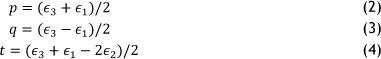

Figure 6: Percentage strain relieved as a function of the hole depth ratio for the combination strains p, q, and t. Note that Dsause is the strain gauge rosette diameter and d is the hole depth.
where ε1; and ε3 are the micro-strains recorded by gauge 1, 2, and 3 (see gauge numbering and gauge orientation in Figure 4).
It is worth noting here that the uniform stress procedure in the ASTM E837-08 test method is only valid for uniform residual stresses not exceeding 50% of the yield strength of the material. The slight irregular deviations observed in Figure 6 indicate the presence of non-uniform residual stresses (this observation was concurrent with the readings from the other strain gauge rosettes) [14,16]. In this case, ASTM E837-08 prescribes a procedure for the analysis of non-uniform stresses using the integral method [14,16]. In addition, since the residual stresses exceeded 50% yield, the correction by Moharami & Sattari-Far for residual stresses approaching the yield strength of the material was used. Equation (5) corrects the residual stresses approaching yield calculated from ASTM E837-08 [17].

where amaxASTM is the maximum principle stress calculated from ASTM E837, ay is the yield strength, and m is calculated from equation (6),

where Ep is the tangent modulus, E is the Young's modulus, and aminASTM is the minimum principle stress calculated from ASTM E837.
Table 1 reports the residual stresses and the confidence intervals using the integral method and the Moharami & Sattari-Far correction procedures on the results obtained from ASTM E837.
Table 1: Residual stress results as performed by ASTM E 837-08 (using the integral method for non-uniform residual stresses) and Moharami & Sattari-Far's correction procedure [17]. (The sector positions are shown in Figure 4.)

3.3. Microstructure evaluation
Etching of the SLM Ti-6Al-4V revealed a predominantly martensitic microstructure with very fine alpha prime (α') plates, shown in Figure 7. This needle-like pattern, which dominates the microstructure, is typical of rapidly-cooled Ti-6Al-4V from above the martensite start temperature (approximately 800°C) [18]. The production of martensitic Ti-6Al-4V is due to the extreme temperature changes as the laser traces across the powder bed. The melting and re-solidification stages as each layer is completed promote the α' structure observed in these specimens. A similar martensitic microstructure and transformation was observed in a previous study by Imam & Gilmore, and was found to increase the fatigue life of the material [19]. This microstructure resembles that found by Ramoseoeu & Chikwanda, for which a hardness of 345 HV10 was determined [20]. This hardness is comparable to that of conventional annealed Ti-6Al-4V, with a reported average hardness of 349 HV10 [18].
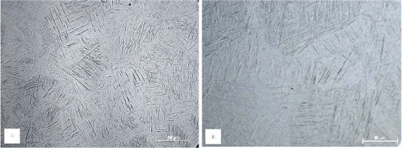
Figure 7: Micrograph of the etched SLM Ti-6Al-4V specimen in the A) longitudinal build direction, and B) the transverse direction.
4. DISCUSSION
The residual stress results shown in Table 1 illustrate high residual stresses present in SLM Ti-6Al-4V. The measurement of such high residual stresses, which approach and exceed the yield strength, suggests that the deformation observed during production may indeed be attributed to residual stresses. These residual stresses are most likely to have formed due to the temperature gradient mechanism (TGM). Mercelis & Kruth [8] have investigated this in stainless steel 316, and made several conclusions based on their residual stress testing, particularly in the region nearest the base plate [8]. Components that remained attached to the base plate contained stress levels near to that of the material yield strength, whereas components removed from the base plate had lower stress levels - and yet deformation was present [5]. One way to minimise the degree of temperature gradients (which seem to cause the high residual stresses) is to equip the sintering machine with a heated powder bed that reduces the severity of the temperature gradient around the laser spot [21].
The martensitic microstructure observed in the specimens in Figure 7 is similar to that found by Ramosoeu & Chikwanda [20]. The fine α' microstructure is produced by the SLM-process, in which rapid temperature changes are experienced together with re-solidification as the laser traces out the subsequent layers. Previous studies into the effect of a martensitic microstructure in Ti-6Al-4V have found it to increase the fatigue life of the material [19]. This was caused by a strain-induced martensitic transformation of retained β phase to martensite [19]. This microstructural characteristic may therefore be promising for the fatigue/fracture behaviour of SLM Ti-6Al-4V.
The density results demonstrate the capability of the SLM system when producing near fully-dense components. This is particularly useful for aerospace applications, in which components are designed near material limits and density considerations become important [22]. The microstructure evaluation did, however, reveal several micro-flaws of various geometries throughout the specimen. These pores may be the result of incomplete powder melting or irregularities in the powder layer [23]. The sharp voids can result in high stress concentrations which, combined with excessively high residual stresses, may pose a serious problem for crack initiation and propagation. Similarly, the high levels [23] of surface roughness and micro-defects near the surface may promote faster crack initiation, although this may be overcome by various post-processing techniques such as shot peening.
An important point worth exploring is the effect of residual stress on the fatigue life performance. High tensile residual stresses become particularly problematic, since these increase the cyclic stress state. An increased cyclic stress state impacts the load carrying capability, increasing the minimum and maximum cyclic stresses in the structure. This cyclic stress ratio is defined as the load ratio R [11]. An increase in the material mean stress due to the presence of residual stresses results in a greater load ratio. In conventional wrought Ti-6Al-4V, the fatigue crack threshold varies significantly between load ratios R = 0.1 and R = 0.9 [24]. Assuming two components, one without any significant residual stress, i.e., R = 0.1, and one with residual stress, i.e., R = 0.9, the fatigue implications would be such that crack initiation would occur for an inherent crack or material flaw that is approximately six times smaller. Keeping in mind the observed porosity of the sintered Ti-6Al-4V material in combination with the high residual stresses, a significant reduction in fatigue life is foreseen. Consequently, the presence of residual stresses has severe implications for the structural integrity of the material. Alleviation of these residual stresses is vital, therefore, in order to ensure the fatigue threshold remains as high as possible for a successful application of Ti-6Al-4V in the aerospace industry.
A complete material characterisation for SLM-produced Ti-6Al-4V is necessary before industry applications can be completed successfully. Some of the most pertinent behavioural characteristics that remain unknown are the creep and fatigue/fracture behaviours. The creep behaviour of this material has not yet been published in the literature; but this would be of great value to aircraft engine manufacturers such as Rolls Royce, since conventional cast and wrought Ti-6Al-4V is creep-limited to operational temperatures of 340°C [6]. The fatigue and fracture behaviour of selective laser melted Ti-6Al-4V needs to be determined; this too has not yet been published in the literature. These mechanisms have been very well researched for bulk Ti-6Al-4V, and similar research into the SLM-produced variant is necessary before this manufacturing technique is implemented in large-scale designs. SLM needs to have minimal post-processing to remain competitive in the rapid manufacture industry in which other processes, such as electron beam melting (EBM), have shown promising results [25]. Methods of residual stress relaxation are thus necessary to ensure that SLM remains a viable manufacturing technique for complex geometries.
5. CONCLUSIONS
- The density tests on the SLM-manufactured Ti-6Al-4V found an average relative density of 99.75%, which confirms the ability of SLM to produce near fully-dense components. The presence of voids and sharp discontinuities in the longitudinal and transverse sections poses a possible threat in the form of premature fatigue crack initiation sites.
- The microstructural evaluation revealed a martensitic microstructure in both the longitudinal (build direction) and the transverse sections. This more brittle microstructure agrees with the previously observed brittle material behaviour.
- The residual stresses were found to be exceedingly high in the specimens, and in some areas approached and exceeded the yield strength of the material. This confirms that the deformation observed in the specimens is due to residual stresses from the selective laser melting process.
6. FUTURE WORK
-
The high residual stresses present in the specimens are a concern for applications of SLM Ti-6Al-4V, especially in the aerospace industry. From a fracture mechanics perspective, high tensile residual stresses can be detrimental, as these may cause premature failure of the component during service. It is thus of particular interest to investigate stress alleviation techniques to reduce the high residual stresses caused by selective laser melting.
Surface roughness defects observed under an optical microscope, and a predominantly martensitic microstructure, have warranted further investigations using digital image correlation (DIC) to observe the possible opening of underlying micro-flaws. This is extended to examining the behaviour of the voids as possible crack initiation sites. - The creep behaviour of selective laser melted Ti-6Al-4V has not yet been published in the literature, and is of particular interest in the aerospace industry in which loads at elevated temperatures are common.
- The fatigue and fracture toughness of selective laser melted Ti-6Al-4V also remains unpublished in the literature. The fatigue and fracture behaviour of this alloy is of paramount importance in the aerospace industry, with particular emphasis on components produced for jet turbine engines, which are subject to high cyclic loading.
7. ACKNOWLEDGEMENTS
The authors would like to express their gratitude to the CSIR for funding this study. In addition we would like to thank the CRPM for providing specimens for this study.
REFERENCES
[1] Casavola, C., Campanelli, S.L. & Pappalettere, C. 2008. Experimental analysis of residual stresses in the selective laser melting process, Proccedings of the XIth International Congress and Exposition, Orlando, Florida, USA. [ Links ]
[2] Murr, L.E., Quinones, S.A., Gaytan, S.M., Lopez, M.I., Rodela, A., Martinez, E.Y., Hernandez, D.H., Martinez, E., Medina, F. & Wicker, R.B. 2009. Microstructure and mechanical behavior of Ti-6Al-4V produced by rapid-layer manufacturing, for biomedical applications, J. Mech. Behav. Biomed. Matter, 2(1), pp. 20-32. [ Links ]
[3] Hollister, S.J. & Bergman, T.L. Biomedical applications of integrated additive/ subtractive manufacturing, Additive/Subtractive Manufacturing Research and Development in Europe, 1001, p. 55. [ Links ]
[4] Vandenbroucke, B. & Kruth, J.-P. 2007. Selective laser melting of biocompatible metals for rapid manufacturing of medical parts, Rapid Prototyping Journal, 13(4), pp. 196-203. [ Links ]
[5] Ritchie, R.O., Boyce, B.L., Campbell, J.P., Roder, O., Thompson, A.W. & Milligan, W.W. 1999. Thresholds for high-cycle fatigue in a turbine engine Ti-6Al-4V alloy, International Journal of Fatigue, 21(7), pp. 653-662. [ Links ]
[6] Leyens, C. & Peters, M. 2003. Titanium and titanium alloys: fundamentals and applications. Wiley-VCH. [ Links ]
[7] Facchini, L., Magalini, E., Robotti, P., Molinari, A., Hòges, S. & Wissenbach, K. 2010. Ductility of a Ti-6Al-4V alloy produced by selective laser melting of prealloyed powders, Rapid Prototyping Journal, 16(6), pp. 450-459. [ Links ]
[8] Mercelis, P. & Kruth, J.P. 2006. Residual stresses in selective laser sintering and selective laser melting, Rapid Prototyping Journal, 12(5), pp. 254-265. [ Links ]
[9] Kruth, J.P., Badrossamay, M., Yasa, E., Deckers, J., Thijs, L. & van Humbeeck, J. 2010. Part and material properties in selective laser melting of metals, Proceedings of the 16th International Symposium on Electromachining. [ Links ]
[10] Matsumoto, M., Shiomi, M., Osakada, K. & Abe, F. 2002. Finite element analysis of single layer forming on metallic powder bed in rapid prototyping by selective laser processing, International Journal of Machine Tools and Manufacture, 42(1), pp. 61-67. [ Links ]
[11] Anderson, T.L. 2005. Fracture mechanics: Fundamentals and applications. Taylor & Francis. [ Links ]
[12] Standard 54 - Determination of Density of impermeable Powder Metallurgy (PM) Materials. Metal Powder Industries Federation, Revision 2010. [ Links ]
[13] Measurement of residual stresses by the hole drilling strain gage method," Technical Note TN- 503-6, Revision: 01-Nov-2010, Vishay Micro Measurements, Pennsylvania. [ Links ]
[14] Schajer, G.S. 1988. Measurement of non-uniform residual stresses using the hole-drilling method. Part I - Stress calculation procedures, J. Eng. Mater. Technol., 110(4), pp. 338-343. [ Links ]
[15] Say, W.C. & Tsai, Y.Y. 2004. Surface characterization of cast Ti-6Al-4V in hydrofluoric-nitric pickling solutions, Surface and Coatings Technology, 176(3), pp. 337-343. [ Links ]
[16] Schajer, G.S. 1988. Measurement of non-uniform residual stresses using the hole-drilling method. Part II - Practical application of the integral method, J. Eng. Mater. Technol., 110(4), pp. 344349. [ Links ]
[17] Moharami, R. & Sattari-Far, I. 2008 Experimental and numerical study of measuring high welding residual stresses by using the blind-hole-drilling technique, The Journal of Strain Analysis for Engineering Design, 43(3), pp. 141-148. [ Links ]
[18] Donachie, M.J. 2000. Titanium: a technical guide. ASM International. [ Links ]
[19] Imam, M.A. & Gilmore, C.M. 1983. Fatigue and microstructural properties of quenched Ti-6Al- 4V, Metallurgical and Materials Transactions A, 14(1), pp. 233-240. [ Links ]
[20] Ramosoeu, M.E., Chikwanda, H.K., Bolokang, A.S., Booysen, G. & Ngonda, T.N. 2010. Additive manufacturing: Characterization of TI-6AI-4V alloy intended for biomedical application, Proceedings from the Light Metals Conference 2010, pp. 337-344. [ Links ]
[21] Zhang, D.Q., Cai, Q.Z., Liu, J.H., Zhang, L. & Li, R.D. 2010. Select laser melting of W-Ni-Fe powders: Simulation and experimental study, Int. J. Adv. Manuf. Technol., 51(5-8), pp. 649-658. [ Links ]
[22] Flower, H.M. 1995. High performance materials in aerospace. Chapman & Hall. [ Links ]
[23] Kruth, J.P., Froyen, L., van Vaerenbergh, J., Mercelis, P., Rombouts, M. & Lauwers, B. 2004. Selective laser melting of iron-based powder, Journal of Materials Processing Technology, 149(1 - 3), pp. 616-622. [ Links ]
[24] Sadananda, K. & Vasudevan, A.K. 2005. Fatigue crack growth behavior of titanium alloys, International Journal of Fatigue, 27(10-12), pp. 1255-1266. [ Links ]
[25] Murr, L.E., Esquivel, E.V., Quinones, S.A., Gaytan, S.M., Lopez, M.I., Martinez, E.Y., Medina, F., Hernandez, D.H., Martinez, E., Martinez, J.L., Stafford, S.W., Brown, D.K., Hoppe, T., Meyers, W., Lindhe, U. & Wicker, R.B. 2009. Microstructures and mechanical properties of electron beam-rapid manufactured Ti-6Al-4V biomedical prototypes compared to wrought Ti-6Al-4V, Materials Characterization, 60(2), pp. 96-105. [ Links ]
* Corresponding author
# This article is an extended version of a paper presented at the 2011 RAPDASA conference.
1 The author is enrolled for an MSc in the Mechanical Engineering Department, University of Cape Town.

