


Services on Demand
Article
 English (pdf)
 Article in xml format
 Article references
Indicators

Related links
-
 Cited by Google
 -
 Similars in Google
Share

 Permalink
South African Journal of Industrial Engineering
On-line version ISSN 2224-7890
Print version ISSN 1012-277X
S. Afr. J. Ind. Eng. vol.23 n.3 Pretoria Jan. 2012
GENERAL ARTICLES
Modular research equipment for on-line inspection in advanced manufacturing systems
S. DavrajhI, *, 1; G. BrightII; R. StopforthIII
IDepartment of Mechanical Engineering University of KwaZulu-Natal, South Africa. sdavrajh@ukzn.ac.za
IIDepartment of Mechanical Engineering University of KwaZulu-Natal, South Africa
IIIDepartment of Mechanical Engineering University of KwaZulu-Natal, South Africa
ABSTRACT
The significance of inspection processes increases when producing parts with high levels of customer input. These processes must adapt to variations in significant product characteristics. Mass customisation and reconfigurable manufacturing are currently being researched as ways to respond to high levels of customer input. This paper presents the research and development of modular inspection equipment that was designed to meet the on-line quality requirements of mass customisation and reconfigurable manufacturing environments. Simulated results were analysed for application in an industrial environment. The implementation of the equipment in South Africa is briefly discussed. The research indicates that manufacturers need only invest in the required equipment configurations when they are needed for on-line inspection.
OPSOMMING
Die belangrikheid van inspeksieprosesse verhoog wannneer onderdele met hoë vlakke van kliëntinsette vervaardig word. Hierdie prosesse moet aanpas by variasies in belangrike produkeienskappe. Massadoelmaking en herkonfigureerbare vervaardinging word tans nagevors as 'n moontlike manier om hoë vlakke van kliëntinsette te hanteer. Hierdie artikel hou die navorsing en ontwikkeling van modulêre inspeksietoerusting voor wat ontwikkel is om aan die "op-die-lyn"-gehaltevereistes van massadoelmaking en herkonfigureerbarre vervaardigingsomgewings te voldoen. Gesimuleerde resultate is geanaliseer vir toepassing in 'n industriële omgewing. Die implementering van die toerusting in Suid-Afrika word kortliks bespreek. Die navorsing toon dat vervaardigers slegs hoef te belê in die nodige toerusting-konfigurasies wanneer dit benodig word vir "op-die-lyn"-inspeksie.
1. INTRODUCTION
Manufacturing systems have evolved over time, from early low-production approaches that satisfy one customer at a time, to achieving economies of scale through mass production technology in the twentieth century [1, 2]. This evolution was made possible by increasing the efficiency and reliability of the relevant dedicated systems used in mass production [2, 3]. Statistical Process Control (SPC), check sheets, control charts, and sampling are some of the quality tools used in predictable manufacturing environments such as dedicated manufacturing systems (DMSs). The current trend in consumer markets is that customers are becoming more diversified and more difficult to satisfy [4-7]. Customers now expect to become more involved in the various stages of product design without having to pay the high price associated with customisation [5, 6]. The diversification of consumer markets increases the difficulty for manufacturers of exploiting niche markets [1, 8]. Modern manufacturers must employ methods of coping with manufacturing requirements, such as the accommodation of frequent product changeover, and variations in products and processes. Changes in government regulations and process technologies can also challenge manufacturers [6]. Mass customisation (MC) and reconfigurable manufacturing systems (RMSs) are modern manufacturing approaches that accommodate high levels of customer input through the implementation of product family architectures (PFAs) [9]. These approaches are still being researched, and are not widely implemented in many countries, including South Africa.
Quality control associated with MC and RMSs has a greater significance than with DMSs, due to wide product varieties and highly uncertain markets. Traditional quality tools are insufficient to cope with modern quality requirements characterised by variations in significant quality characteristics, low-volume production, high levels of automation, and often unique inspection requirements [4, 10-12]. Coordinate measuring machines (CMMs) are not suitable for high volume production, and inspection equipment used in DMSs is often too rigid for modern inspection requirements [13]. Quality control for manufacturing environments that perform mass production with high levels of customisation needs to be researched further [5, 6, 12]. Da Silveira et al. [5] stated that the success of a quality control system depended on the definition of significant quality characteristics, and the availability of data on those characteristics. This statement implied that variations in the significant features of products would require variations in the sensing capabilities and configuration of the associated inspection equipment. Research into low-cost inspection equipment to perform quality control within these environments therefore also needs to be considered. This paper presents the development of research equipment aimed for use in a MC or RMS environment. Modular designs were conceptualised for quality control of parts that varied in inspection requirements, without significantly affecting the time and cost of a manufacturing process. Inspection of significant regions of interest (ROIs) on moving parts was performed in order to minimise the effect of the quality inspection routines on production throughputs. The use of modular inspection hardware allowed for only the required inspection equipment to be used in an inspection routine. The implementation of a minimal amount of inspection equipment implied that manufacturers would be able to invest only in relevant mechanical, electrical, electronic, and software modules. The industrial implications within a South African manufacturing context are also considered.
2. INSPECTION EQUIPMENT REQUIREMENTS
The disadvantages of existing inspection systems include high set-up costs of equipment that is not designed to accommodate new applications easily [14]. The costs of investing in new quality inspection equipment can deter manufacturing organisations from implementing stringent quality control throughout the manufacturing lifecycle of their products. This lack of quality control throughout numerous processes can lead to excessive wastage and possibly to the production of defective products, thus decreasing customer satisfaction and loyalty.
RMSs are designed to produce a great variety of products within a part family at high volume and economically [6, 15]. The modular design of RMSs allows for a process to be reconfigured by rearranging process modules. This reconfiguration implies that RMSs are more flexible and responsive to market changes than DMSs - and more cost-effective and less complex than flexible manufacturing systems (FMSs) [6, 16]. RMS configurations are aimed at providing a DMS that is customised around the target product [17], thereby providing customised flexibility through reconfiguration, as opposed to general flexibility through a variety of dedicated equipment with built-in high functionality, as in FMSs [18]. PFAs are therefore crucial to the implementation of an RMS [19].
According to Da Silveira et al. [5], MC is defined as "a system using information technology, flexible processes, and organizational structures to deliver a wide range of products and services that meet specific needs of individual customers at a cost near that of mass-produced items". PFAs are a key method to optimise external variety with internal complexity in an MC environment. MC aims to satisfy a wide spectrum of customer requirements from standardised products to purely customised products. The agility and flexibility of a manufacturing system are considered crucial MC implementation enablers. Zhao et al. [20] argue that more research needs to be conducted into the implementation of quality systems for implementation in MC environments. According to Joergson et al. [9], the modular approach of RMSs corresponds to the assembly and fabrication stages in the MC spectrum. Table 1 summarises the requirements of inspection equipment to control the quality for MC and RMSs, based on the characteristics of these environments.
Table 1: Inspection equipment requirements for MC and RMSs

It was suggested by Davrajh & Bright [13] that it was possible to defend a production rate while performing high frequencies of inspection by inspecting only significant regions of interest (ROIs) on moving parts. Parts were classified according to the shape of their volumes, and ROIs were predefined by the user. The disadvantages of the apparatus discussed were that the inspection routines were limited to the use of only one vision sensor, and the apparatus could not be easily implemented on an existing conveyor system. The equipment was also limited to degrees of freedom of the sensor articulation system. The University of Michigan developed the reconfigurable inspection machine, which focused on the inspection of cylinder heads [15]. This apparatus was able accurately to inspect cylinder heads without a significant impact on production rates. The disadvantages with this system were that the inspection routines were limited to the inspection of cylinder heads, and the high costs involved with the equipment made investment in this process less attractive. The relevance and advantages of using modular machines for reconfigurable manufacturing have been discussed by Padayachee [21].
A review of the literature concluded that the area of on-line quality control that required research was the implementation of low-cost modular inspection hardware in environments that experienced frequent product changeover. The concepts of classifying part families [19] into rectangular and cylindrical volumes, as well as the inspection of ROIs on moving parts, were adapted from previous research [13]. The implementation of modular hardware was identified as the best strategy for varying products.
3. METHODOLOGY
The apparatus was designed with concurrent consideration of the mechanical design, electrical and electronic components, and software used to control the equipment. The focus of the research was to incorporate low-cost modularity with respect to sensory systems, sensor articulation, drive systems, and software systems. The equipment had to be easily implemented over an existing conveyor system. Product architectures were divided into rectangular and cylindrical volumes. Users were allowed to select up to three and five ROIs for cylindrical and rectangular part families respectively. Significant ROIs were determined by an operator, based on customer requirements. Figure 1 shows the cycle of information from the customer to the inspection equipment, and the sequence of operation of the conceptualised equipment. The customer-manufacturer interface (block A) was the decoupling point of the customer input. The function of this interface was to convert customer functionality into features and ROIs on the specific part. The processes involved in mapping customer quality requirements on to process configurations are shown in block B. The inputs were brought to bear on the configuration of the processes by converting user-defined ROIs into specific sensor co-ordinates and orientation. Manufacturer feedback (block C) was responsible for indicating the location and nature of defects on inspected ROIs. Block D was the acceptable product delivered to the customer. Blocks A and D were the only stages of the product lifecycle visible to the customer. This limited interaction allowed for customers to dictate the design of the product without significantly dictating the dynamics of the inspection routines and process dynamics.
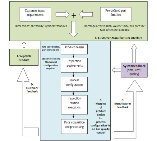
Figure 1: Representation of the information flow associated with the conceptualised system
3.1 Mechanical design
The mechanical design of the equipment involved the mechanical modules that provided the degrees of freedom (DOFs) for the required sensor articulation when inspecting a range of parts with various dimensions and ROIs. The structural and dynamic integrity of the different configurations of modules during operation of the equipment was also considered. Gantry architecture was considered for the layout of the mechanical modules. The reason for selecting this configuration of manipulator was that it was less complex and more dexterous than parallel architectures, while being easier to integrate into an existing conveyor system than a serial manipulator (with respect to collision avoidance). A library of mechanical modules was designed and divided into translational and rotational motions. The configuration of mechanical modules selected, and the DOFs, were both a function of the type of sensor, the ROIs, the part dimensions, and speed. Assembly of mechanical modules that matched the ROI locations on different parts are shown in Figures 2 (a)-(c). Figures 2 (a) and (b) display the concept of using the same mechanical modules in different configurations to inspect different ROIs within the same part family.


Figure 2 (a)-(c): Different configurations of modules based on ROIs
The structural integrity of the translational motion modules was determined by comparing the bending stress to the yield stress [22] of the support bars. The bending stress experienced by the support bars of a module, in a system with n modules, was calculated using equation (1):

where
σ 1 was the stress experienced by the ith member
M n-i was the moment experienced by the ith member as a result of the n-i members it supported
M i was the moment experienced by the ith member as a result of its own weight
y i was the distance from the neutral axis of the support bar to the point of loading on the ith member
Ii was the polar moment of the ith member
The deflection of the sensor during operation of the equipment was determined by accounting for the deflection of the module that the sensor was attached to, as well as the deflections of the other modules that connected the sensor to the ground (link 0). The equation used to simulate the vibration of the sensor was determined using energy methods, and was calculated using equation (2) [23]. This model was based only on the vertical deflection of the sensor, and did not accommodate rotational effects in trying to achieve a generic representation of the vibrations.

where
Ysensor was the deflection of the sensor while the supporting module i was in motion
δi was the static deflection experienced by the ith member as a result of the members it supported
g was the gravitational constant of acceleration
V i was the linear translational speed of the ith member
The trajectory of the sensor was limited to the workspace of the gantry architecture. It was assumed that the rotational actuation modules would be located after the translational modules, due to the nature of the mechanical architecture. In a configuration of n modules, the relationship between the positions of the sensor and the frame of reference on the equipment was represented by equation (3) [24].

where
0Psensor was the position vector of the centre of the sensor relative to reference frame 0 (ground)
nPsensor was the position vector of the centre of the sensor relative to the last module n (gripper)
 was the transformation matrix used to map the relationship between module i and i-1 using the centres of the interfaces of modules as the origins of the frames.
These matrices would depend on the number of translational and rotational modules, and were therefore specific to each possible configuration.
For the non-trivial case of the user selecting more than two ROIs (for rectangular part families), an algorithm was developed to determine the best sequence to follow, with the paths being specified between ROIs (in order to avoid collisions between the moving part and sensor). This algorithm was based on the greedy-first approach: it started from the front face as a default, moving along to the nearest ROI and to the last face, and then finally returning to the initial starting point.
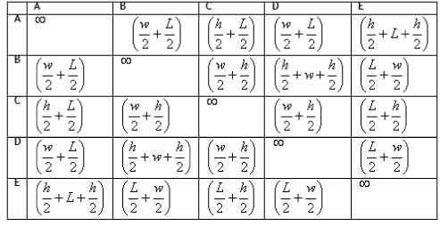
As an example, consider a product with dimensions w, L and h, shown in Figure 3. The dimensions of this product are considered to account for the clearance required to accommodate the required field of the sensor used. The distances between ROIs are given in Table 2. The distance between an ROI and itself was considered to be infinity ( oo ) to avoid a non-hamiltonian loop. Assuming the user was interested in all ROIs except on Face D, the path followed would include the ROIs on Faces A, B, C, and E (with the location of the ROIs at the vertical and horizontal centres of the relevant faces). The last motion would be from E to the initial point where the inspection process began (since the part had moved from time =0). The resulting times between ROIs were then calculated as the distances of the paths (shown in dashed lines) divided by the velocities in the respective directions. The sensor was assumed to be relatively stationary in relation to the part while it was moving. This assumption was achieved through moving the sensor at the same velocity as the part in the direction of the part motion for the duration of the inspection process.
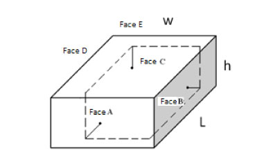
Figure 3: Rectangular part with dimensions w, L and h
Table 2: Distances between ROIs as a function of part dimensions
3.2 Electrical/electronic design
The electronic system was divided into data acquisition, data transmission, motor control, and part identification. A barcode scanner was used for part identification. The entire system was initiated through detection of the part, via a break in the line sensors placed on the conveyor preceding the apparatus. For the given gantry manipulator, not more than three translational modules were considered. Figures 4 (a) and (b) show the electronic layout of the modules and the electronic control modules respectively. The flow of information started from the line sensors, which activated the inspection routine. The host PC then sequenced the motions required by sending signals through a USB port to the USB hub. (A USB hub was used, since more motion control modules could be added using the FT232 interface boards.) The slave controllers (motor controllers) were passed the number of pulses and speed required. These slave controllers then independently controlled each motor while obtaining feedback from encoders. The host PC concurrently sequenced the time for the data acquisition by the relevant sensors. The sensors selected for this application were vision, magnetic, and proximity sensors. Signal conditioning was implemented to ensure that all sensors could be directly connected to USB ports on the host controller. The sensor articulation was actuated through control of DC motors, using rotary encoders for speed and position control. Servos were also used to pan and tilt the sensors. Motor control boards were designed and implemented to incorporate reconfigurability within the electronic system. These boards consisted of commercially-available H-bridges, microcontrollers, and USB interfaces (for signal conditioning purposes) [25]. The control boards were also designed to be scalable, in that the commercially-available circuitry could easily be replaced by higher capacity control boards, should an increase in the motor sizes and power be required. Modular control circuitry with USB interfacing allowed for more motors to be controlled simply by adding more modules. A cascaded feedback control loop was implemented for the accurate control of speed and position of the sensor articulation motors. A PID controller was used to ramp the translational actuators up and down to ensure a greater degree of accuracy in positioning the sensor.

Figure 4(a): Layout of electronic modules
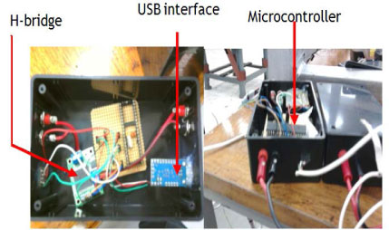
Figure 4(b): Motion control modules
3.3 Software design
The software was responsible for providing an interface between the user and the inspection routine, sequencing the operation of the mechanical and electrical hardware, and deciding on the status of a part. Visual Basic was the selected as the programming language for the main user interface. The GUI consisted of sequential forms that were accessed in correlation with the user requirements of part classification, dimensions, ROIs, and types of sensing required. The control of the relevant motors was achieved by accessing the time and distance parameters passed through the GUI, and then converting these values into the variable declared in the coding of the microcontrollers, which were programmed in C using the CAVR software package. The image processing was achieved by compiling utility files in VB.net, which allowed for the image processing steps to be modularised. Different modules were accessed according to the user specification. The software suggested the path for the sensors during the inspection routine, based on a predefined sequence of access to different faces. If this sequence did not yield an acceptable path with respect to time (production rate), the user was allowed to interchange the order of the sequence of access to the various faces. Figure 5 illustrates the electronic layout of the equipment, along with some of the software modules.

Figure 5: System layout of software and electronic hardware
Figure 6 illustrates the flow of information within the software architecture. A high-level GUI written in VB.net was programmed to process customer requirements, and converted the ROIs into physical coordinates on a moving part frame. Low-level programming in the CAVR software package enabled the implementation of speed and position control algorithms on the microcontrollers. Signal conditioning was achieved through the use of H-bridges and controllers accompanying some of the sensors used. Once sufficient information about the specified ROIs was obtained, a decision based on a specified tolerance was made either to accept or to reject the part.

Figure 6: Information flow within software architecture
4. RESULTS AND DISCUSSION
The use of a gantry architecture meant that the first module would always be across the conveyor and so would have to be supported at either end of the conveyor. This module would therefore be supporting the weight of all other modules. It was decided to consider only the worst-case bending of the first module, as it would experience the highest loading as a result of the other modules it supported. This decision was justified through duplication of the support bars, used for the first module, in other modules. The maximum stress induced on the support bars was calculated using equation (1), and was found to be 72 MPa with a safety factor of 2. The structure was therefore considered to be statically safe, since the yield stress of the steel used was approximately 210 MPa. Assuming a maximum total velocity of 0.5m/s and a maximum static deflection of 1mm, the maximum deflection due to dynamic loading on the first module was found to be less than 2 mm using equation (2). This deflection was within the limitations of the image processing algorithms. Figure 7 shows the constructed modules in different configurations. The vertical supporting steel members were found to be unstable during motion, and steel plates had to be added to the bases of each vertical member to increase overall stability.

Figure 7: Constructed modules in different configurations
Table 3 lists the times taken to assemble each module. These times were based on, and included, the time taken to assemble the X-axis supports as the initial modules. The times indicate that the downtime required for reconfiguration was not ideally suited to batch-of-1 production. Instead, batches of products that were to change on a monthly basis would be a more suitable environment to implement this equipment. The significant decrease in times taken to assemble the modules from Run 1 to Run 3 for all axes was due to operators becoming more accustomed to the techniques and sequences required to minimise the assembly times of the equipment. This significant decrease in times indicated that specifically-trained operators were required for the efficient setup of the equipment, and that this would add to the setup costs associated with the modules. The data in Table 3 also suggested that operators should try configurations of the Z and X axes modules prior to implementation of the in-line Y-axis module. Due to limitations of the laboratory environment, no data has been recorded on the ramp-up times and overall costs of the actual equipment from setup to high throughput rates.

Table 3: Module assembly times
The sensor articulation system was first analysed by inspecting the performance of each degree of freedom. Following acceptable performance by the different modules, the overall accuracy and repeatability of this system was tested by determining the errors between the allocated and actual positions of the sensor with respect to a global reference frame. The accuracy of each image processing module was tested by inspecting a known part. The actual parameters of the part were measured against the obtained data, and these errors were reduced through further optimisation of the image processing threshold values. Table 4 summarises the results of an inspection routine and modules and image processing operations required for inspection of a part with multiple ROIs that required implementation of multiple DOFs. The purpose of the inspection was to determine the presence of five holes on the front face of the part before a bearing was inserted into the middle hole. Checking for the presence of the bearing was followed by inspection of the three mounting holes required on the top face of the part. This inspection routine occurred in multiple stages following the addition of each feature to the base platform. Inspection after each manufacturing process was considered for early detection of product flaws. The use of multiple modules (x, y, z, and pan and tilt) allowed for this product to be inspected without having physically to add or remove modules. Image processing operations were also structured in a modular order, and the processing modules were referred to when necessary.
Table 4: Inspection of multiple ROIs without needing to change inspection modules

Figures 8 (a), (b) and (c) show respectively the ROI on a cylinder used to store pharmaceutical effervescent, the required process configuration, and the resulting GUI following the inspection routine. A metal detector was used to detect the presence of the metal foil in the cylinder. No degrees of freedom were required by the sensor, as no relative motion was required between the sensor and the part. Motion in the x and z-axes could have been used to accommodate similar inspection routines with different part heights and widths. This inspection routine was subject to the sensitivity and range of the sensor used.
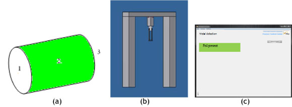
Figure 8(a)-(c): Metal detection routine for cylindrical part
5. INDUSTRIAL CONSEQUENCES
5.1 Impact of modular inspection equipment
The quality costs associated with a production system include the costs of prevention, appraisal, and external and internal failure [27]. The planning of the system layout constitutes part of the prevention costs. The operational costs of the inspection equipment form part of the appraisal costs. The use of only relevant inspection modules when required will reduce the overall quality costs of a system as follows:
- Prevention costs: The reduction in capital expenditure will result in a reduction of the initial setup of the quality stations in a system.
- Appraisal costs: This cost will be reduced, since less expenditure will be required due to the implementation only of necessary modules.
- Internal failures: The inspection at different stages in a manufacturing system will allow for the early detection of flawed products. This will result in reduced scrapping costs at later stages of the products lifecycle, at which time the investment in the product is high.
- External failures: The high frequency of inspection will result in a reduced number of defective parts being delivered to customers.
A simulation was performed, using the FlexSim Process Simulator [26], to verify the estimated performance of the equipment in a manufacturing environment. Figure 9 shows the layout considered. Two part sources were implemented to simulate the generation of two product families. Two lines of dedicated processors were used for each product family. A single quality station that represented the modular inspection equipment was selected to accommodate both product families. The results of the simulation indicated that the inspection of both part families was accommodated without having to invest in two sets of dedicated inspection equipment. These results suggested that companies needed to invest only in the inspection capacity required; and this could be achieved through the design of modular inspection equipment. The overall quality costs in a manufacturing system would thus be reduced by implementing modular inspection equipment. It would therefore increase the possibility of a quicker return on investment, and so encourage manufacturers to employ the necessary stringent quality strategies through use of these items of modular equipment.

Figure 9: Simulated processing of two part families with one inspection station
5.2 Industrial contribution
The contribution of modular inspection equipment would potentially be that more companies would be willing to invest in implementing stricter quality control methods. Original equipment manufacturers (OEMs) would benefit from the increase in reliability and reduced costs of different tier suppliers who implement stricter quality control in their manufacturing processes. Tier 1, 2, etc. suppliers who implement modular inspection equipment would benefit by achieving higher reliability ratings, while reducing overall manufacturing costs. The different quality standards imposed on these types of manufacturers by a variety of outsourcing companies can be achieved by customising the quality control processes for each company.
According to a survey performed by Erasmus & Van Waveren [28], the following information was gathered in a survey of 35 South African manufacturing companies:
- Fewer than half performed in-house design.
- Only one-quarter had any inclination to use design methodologies (design quality).
- Most companies were aware of international QM strategies. In particular, 60% were ISO 9001 certified.
- The concept of quality was regarded highly in SA. Overall reject rates of 3.5% on average.
- 90% believed that there was potential to grow on local soil.
- 80% showed interest in international markets.
- 70% believed that they were comparable to or better than international offerings.
The implications of this research were that the majority of South African companies outsourced their work (a key strategy in MC product modules), and believed that they were capable of adhering to international quality standards. These traits, coupled with the possibility of growth on local soil, encourage the implementation of MC and RMS manufacturing strategies in South Africa in the near future. The potential for the implementation of modular inspection equipment in South Africa thus becomes more significant.
6. CONCLUSION
The introduction of high varieties of products in mass customisation and reconfigurable manufacturing requires corresponding changes in the quality control inspection systems of those products. Modular inspection architectures were researched. It was concluded that modular inspection systems would be suitable in environments that experience frequent product changeover. It was possible that manufacturers needed to invest only in the mechanical and electrical flexibility (with respect to sensor selection and articulation) that was required for a particular product family. However, a problem lies in the fact that many countries have not yet implemented advanced manufacturing strategies such as RMSs and MC. Physical testing of the designed equipment in an industrial environment will thus be difficult. The optimisation of the layout of the inspection equipment, and the frequency of inspection at these stations, will also need to be considered for successful implementation in a manufacturing system.
The implicit reduction in costs while defending throughputs will benefit both OEMs and manufacturers on different tiers in the supply chain. The flexibility, costs, and throughput capacity associated with modular inspection equipment will encourage local manufacturers to invest in higher levels of quality control, and increase their reliability for a wider spectrum of customers on a global scale.
REFERENCES
[1] Nambiar, A.N. 2009. Mass customization: Where do we go from here? World Congress on Engineering, 2009, p. 687. [ Links ]
[2] Sower, V.E. 2010. Essentials of quality with cases and experiential exercises. 1st ed., John Wiley & Sons. [ Links ]
[3] Mekid, S., Pruschek, P. & Hernandez, J. 2009. Beyond intelligent manufacturing: A new generation of flexible intelligent NC machines. Mechanism and Machine Theory, 44(2), pp. 466476. [ Links ]
[4] Xiaosong, Z., Zhen, H., Fangfang, G., Pengfei, Z. & Dainuan, Y. 2008. The quality forecasting of mass customization based on support vector machines, IEEE International Conference on Service Operations and Logistics, and Informatics, 12-15 Oct. 2008, Vol.1, pp.647-649. [ Links ]
[5] Da Silveira, G., Borenstein, D. & Fogliatto, F.S. 2001. Mass customization: Literature review and research directions, International Journal of Production Economics, 72(1), pp. 1-13. [ Links ]
[6] Koren, Y., Heisel, U., Jovane, F., Moriwaki, T., Pritschow, G., Ulsoy, G. & Van Brussel, H. 1999. Reconfigurable manufacturing systems. CIRP Annals - Manufacturing Technology, 48(2), pp. 527-540. [ Links ]
[7] Tseng, M.M. & Du, X. 1998. Design by customers for mass customisation products, CIRP Annals - Manufacturing Technology, 47(1), pp. 103-106. [ Links ]
[8] Piller, F.T. 2007. Observations on the present and future of mass customisation. International Journal of Flexible Manufacturing Systems, 19(4), pp. 630-636. [ Links ]
[9] Joergensen, N.S., Joergensen, N.K. & Nielsen, K.A. 2010. Reconfigurable manufacturing systems as an application of mass customisation, International Journal of Industrial Engineering and Management, 1(3), p. 8. [ Links ]
[10] Hassan A., Baksh, M.S.N. & Shaharoun, A.M.. 2000. Issues in quality engineering research, International Journal of Quality and Reliability Management, 17(8), p. 18. [ Links ]
[11] Burgess, T. 1999. Quality management for manufacturers of short run semi-customized products. The TQM Magazine, 11, pp. 248-252. [ Links ]
[12] Brabazon, P.G. 2007. Consideration of the relevance of standard quality techniques in mass customisation. International Journal of Mass Customisation, 2(1), p. 76. [ Links ]
[13] Davrajh, S. & Bright, G. 2010. An automated apparatus for dynamic inspection of mass-produced custom parts, Assembly Automation, 30, pp. 47-55. [ Links ]
[14] Garcia, H.C. & Villalobos, J.R. 2007. Automated feature selection methodology for reconfigurable automated visual inspection systems: Automated Feature Selection Methodology for Reconfigurable Automated Visual Inspection Systems, Proceedings of the 3rd Annual IEEE Conference on Automation Science and Engineering, Scottsdale, AZ, USA, Sept 22-25, 2007, pp. 542-547 [ Links ]
[15] Barhak, J., Djurdjanovic, D., Spicer, P. & Katz, R. 2005. Integration of reconfigurable inspection with stream of variations methodology. International Journal of Machine Tools and Manufacture, 45(4-5), pp. 407-419. [ Links ]
[16] Setchi, R.M. & Lagos, N. 2004. Reconfigurability and reconfigurable manufacturing systems: State-of-the-art review, IEEE International Conference on Industrial Informatics, 26 June 2004, pp. 529-535. [ Links ]
[17] Koren, Y. 2006. General RMS characteristics: Comparison with dedicated and flexible systems. Springer. [ Links ]
[18] Mehrabi, M.G., Ulsoy, A.G. & Koren, Y. 2000. Reconfigurable manufacturing systems: Key to future manufacturing, Journal of Intelligent Manufacturing, 11(4), pp. 403-419. [ Links ]
[19] Du, X. 2001. Architecture of product family: Fundamentals and methodology, Concurrent Engineering: Research and Applications, 9(4), p. 309. [ Links ]
[20] Fangfang, Z., Zhen, H. & Du, W. 2008. Quality assurance of mass customisation: A state-of-the-art review, IEEE Symposium on Advanced Management of Information for Globalized Enterprises, 28-29 September 2008, pp 1-3. [ Links ]
[21] Padayachee, J., Bright, G. & Masekamela, I. 2009. Modular reconfigurable machine tools: Design, control and evaluation, South African Journal of Industrial Engineering, 20(2), pp. 127143. [ Links ]
[22] Hibbeler, R. 2008. Mechanics of materials. 7th ed. Prentice Hall. [ Links ]
[23] McCallion, H. 1973. Vibration of linear mechanical systems. Longman Group Ltd. [ Links ]
[24] Craig, J.J. 2005. Introduction to robotics: Mechanics and control, 3rd ed., Pearson Prentice Hall. [ Links ]
[25] http://www.netram.co.za/, accessed 14 July 2011. [ Links ]
[26] FlexSim - software for the visualization, modeling, and simulation of manufacturing, material handling, and logistics systems. [Online]. Available from: http://www.tmn.com.au/Flexsim_Brochure_LoRes.pdf (accessed 15 October 2011). [ Links ]
[27] Besterfield, D.H. 2009. Quality control, Pearson Education Inc., New Jersey. [ Links ]
[28] Erasmus, P. & Van Waveren, C. 2009. Evaluation of quality concepts influencing a manufacturing environment in South Africa, South African Journal for Industrial Engineering, 20(2), pp. 93-105. [ Links ]
* Corresponding author.
1 The author is enrolled for a PhD Eng (Mechanical) degree in the Department of Mechanical Engineering, University of KwaZulu-Natal.

