


Serviços Personalizados
Artigo
 Inglês (pdf)
 Artigo em XML
 Referências do artigo
Indicadores

Links relacionados
-
 Citado por Google
 -
 Similares em Google
Compartilhar

 Permalink
South African Journal of Industrial Engineering
versão On-line ISSN 2224-7890
versão impressa ISSN 1012-277X
S. Afr. J. Ind. Eng. vol.23 no.2 Pretoria Jan. 2012
Limited run production using alumide® tooling for the plastic injection moulding process#
J. CombrinckI; G.J. BooysenII; J.G. van der WaltIII; D.J. de BeerIV
ISchool of Mechanical Engineering and Applied Mathematics Central University of Technology, South Africa. mjcombrinck@telkomsa.net
IISchool of Mechanical Engineering and Applied Mathematics Central University of Technology, South Africa. gbooysen@cut.ac.za
IIISchool of Mechanical Engineering and Applied Mathematics Central University of Technology, South Africa. jgvdwalt@cut.ac.za
IVTechnology Transfer and Innovation Directorate Vaal University of Technology, South Africa deond@vut.ac.za
ABSTRACT
Existing techniques for the production of conventional steel tooling for plastic injection moulding are expensive and time-consuming. As a result, many new products often do not advance beyond the prototype stage. This paper describes an investigation into the possibility of using laser sintered Alumide® (an aluminium-filled nylon material) in a novel alternative process for producing hybrid rapid tooling tools. Initial experiments performed by researchers at the Central University of Technology have shown excellent results. An Alumide® tool can be manufactured in a shorter time and at a significantly lower cost than the same size direct metal laser sintered tool.
OPSOMMING
Bestaande tegnieke vir die vervaardiging van konvensionele staal gietstukke vir die plastiek spuit-giet proses is duur en tydrowend. Die gevolg hiervan is dat baie nuwe produkte nie verder as die prototipe stadium vorder nie. Hierdie artikel ondersoek die moontlikheid om laser gesinterde Alumide® (aluminium gevulde nylon materiaal) in 'n nuwe benadering as 'n alternatiewe proses vir die vervaardiging van snel hibried-gietvorms te gebruik. Aanvanklike eksperimente uitgevoer deur navorsers aan die Sentrale Universiteit vir Tegnologie het uitstekende resultate gelewer. 'n Alumide® gietvorm kan vinniger en goedkoper vervaardig word as dieselfde grootte direk metaal gesinterde gietvorm.
1. INTRODUCTION
The production of tooling for plastic injection moulding (IM) through conventional machining techniques is prohibitively expensive. So many new products are not realised, as inventors are reluctant to take the risk of investing a great deal of money in the tooling of a product that may not succeed commercially [8]. When conventional tooling is removed from the equation, it becomes more feasible to introduce new products in low quantities, which can then be used to investigate the possible market potential [7].
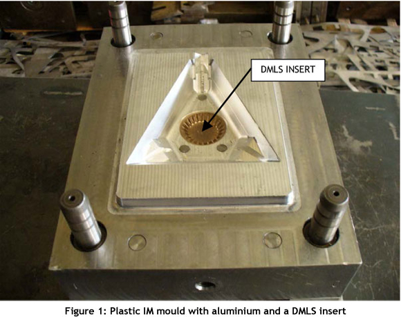
Rapid tooling (RT) was developed as a way to address the long manufacturing lead time, and simultaneously to decrease the cost of tooling for IM. This involves the use of materials (such as aluminium) that are easier to machine than the tool steel normally used for producing IM moulds. The aluminium halves of the mould are produced in the form of inserts, which are mounted into a recess machined into the steel bolsters. Very complicated mould parts can be produced through an additive manufacturing (AM) process, such as direct metal laser sintering (DMLS), and inserted into the aluminium moulds. DMLS involves the sintering of metallic powders in a layer-by-layer process with a high power laser. Because of the high manufacturing cost associated with DMLS inserts, the sizes of the inserts have to be kept as small as possible for this technique to be affordable. Figure 1 illustrates a mould with aluminium and a DMLS insert.
1.1 Rapid tooling
The demand for faster ways of making prototypes, manufactured from the correct material using the appropriate production method, has led to the development of rapid tooling (RT) techniques. RT provides ways to manufacture moulds rapidly, while rapid or direct manufacturing involves techniques for low-volume part production [1].
The potential of RT led to significant interest in solutions for product design and manufacturing. Whether RT is used for prototype, short run, or production tooling, it offers an opportunity to reduce both time and expense of product development [8]. Some of the advantages of RT are:
- Shortening of the tooling lead time [9].
- Lower cost of tooling (cost is reduced due to the shortened lead time) [11].
- Functional testing of parts in an early design stage is possible (due to the shortened lead time, many engineers prefer to produce parts for functional tests), leading to a point where most of the faults are rectified before production [3].
- Automation (many of the RT processes can build tooling sets 24 hours a day, seven days a week).
- Building multiple cavity-core sets (additional cavity-core sets can be built with the first set at reduced cost).
- Creative design possibilities (the possibilities are not limited to creating a design that is manufacturable with traditional techniques) [5].
Some of the disadvantages of RT are:
- Cost effectiveness: The cost of materials and equipment creates high overheads, associated with most RT techniques.
- Size limitations: Many of the RT methods are limited to the size of the inserts that can be created.
- Tool life: Most of the RT options have a limited tool life due to the materials of the cavity inserts [10].
2. ALUMIDE® AS A RAPID TOOLING ALTERNATIVE
Alumide® from electro-optical systems (EOS) is an aluminium-filled nylon material that produces a metallic-look, non-porous component when processed through AM. It can be easily machined, and its material data sheets (MDS) quote temperature resistance up to 170°C. Typical applications for Alumide® are for the manufacturing of stiff parts with a metallic appearance for applications in automotive part manufacturing, for illustrative models, and for jig manufacturing.
2.1 Alumide® tooling trials
Technimark, an industry partner of the Centre for Rapid Prototyping and Manufacturing (CRPM) of the Central University of Technology (CUT), had experience in the development of pre-paid electricity meters. They decided to tender for a new meter development aimed at the South American market. As part of the tender process, the client was required to submit injection-moulded parts to prove manufacturing capability. Not knowing if the tender would be successful, Technimark simplified the design using standard commercially available parts, thus enabling them to produce only special jigs and fixtures in order to develop a risk-free new product. The product required two different IM parts, which required that four mould halves be manufactured within less than four weeks - about one-third of the conventional time.
Taking the development and tender process time into account, it was considered risky to commit expenses. The result was a conservative budget. Instead of production moulds, Alumide® inserts were grown that fitted into steel bolsters. Basic mould finishing and polishing was performed on the Alumide® inserts. Plastic parts produced from the moulds flashed slightly, and this needed to be trimmed away. Two hundred and thirty parts were successfully moulded in acrylonitrile butadiene styrene (ABS) material, using the Alumide® inserts without any visible mould damage or wear. Technimark's tooling trial run proved that Alumide® could be successfully used as an RT medium in limited run plastic applications [4].
During case studies conducted for an M Tech thesis by Mr. G.J. Booysen at the CUT, it was shown that Alumide® inserts could repeatedly withstand an injection temperature of 205°C for 800 to 1,000 injection-moulded shots. In this experiment, only surface cooling (by blowing compressed air on to the moulding surfaces of the opened mould halves during ejection) was used to cool the mould. The cost to manufacture Alumide® inserts was 50% to 75% less than inserts manufactured through conventional methods, and about 50% less than metal laser sintered inserts [2].
2.2 Build considerations for Alumide® inserts
During the design process for the Alumide® inserts, the following should be considered:
- Unlike the DMLS - where the insert size must be kept as small as possible - Alumide® inserts can take up the entire cavity because of the comparatively low cost of producing them. Alumide® inserts can be manufactured in about 30% of the time that it takes to produce the same size DMLS insert. The material cost of Alumide® is about four times cheaper than the DMLS material.
- If there are deep slots in the geometry, post-processing will be necessary and draft angles must be adapted, owing to the surface roughness of the vertical planes (the stair-step effect that is common with the AM process).
- In order to mould a part with small hole features, metal pins should be inserted in the Alumide® inserts to correspond with the location of the required holes in the moulded part. When fitting the insert into the bolster, the insert's edges are usually milled. A machining allowance of about 0.5 mm should be planned on the shut-off surfaces. When fitting the Alumide® inserts into the bolster, not only should the clamping force of the mould be exerted on the Alumide® inserts, but also the force should be shared between the inserts and the bolster.
- Threaded holes must be designed as simple holes. The holes must be about 1 mm smaller than the prescribed drill size. It is then drilled and tapped.
- Ejector pin holes must be designed to be about 0.6 mm smaller than the prescribed size, and then reamed.
- The insert must be shelled to reduce warpage during the manufacturing process. This reduces the building time and the cost to manufacture the insert.
3. METHODOLOGY
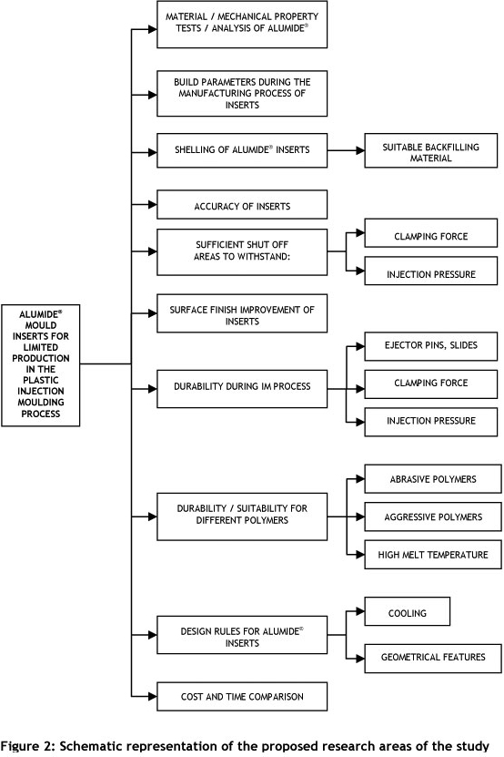
The aim of the research is to evaluate the effectiveness of Alumide® as an alternative medium in which to manufacture RT inserts, thus reducing the cost of tooling for the IM process. Figure 2 shows a schematic diagram of the different research areas that will be investigated as part of the research.
4. RESEARCH AREAS
From Figure 2, the following aspects of Alumide® as a tooling medium have been investigated so far:
- Mechanical properties of Alumide®.
- Shelling of Alumide® inserts.
- Accuracy of Alumide® inserts.
4.1 Mechanical properties of Alumide®
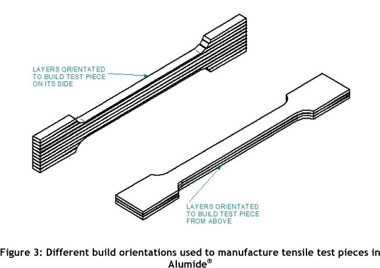
Tensile test pieces were grown in Alumide®, using standard scanning build parameters on the laser sintering machine. The build orientations used to manufacture the test pieces are shown in Figure 3.
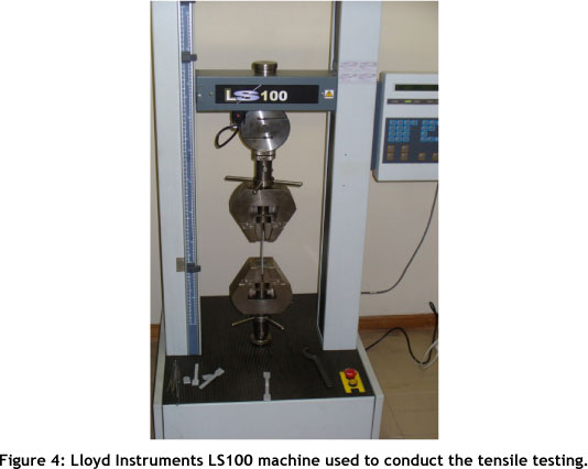
Tensile strength tests were performed on the test pieces at the CUT, using a Lloyd Instruments LS100 testing machine, as shown in Figure 4.
Tests were conducted on five test pieces per build orientation, as shown in Figure 5.
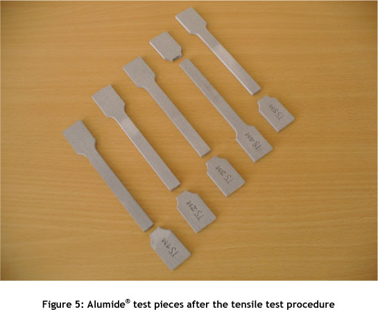
The results from the tensile testing of the Alumide® test pieces are summarised in Table 1, from which we can conclude that the build orientation has a significant influence on the Young's modulus and tensile strength of a test piece. This can be explained by how effectively one sintered layer is 'bonded' to the previous one, and by the cross-sectional area of the sintered layers.
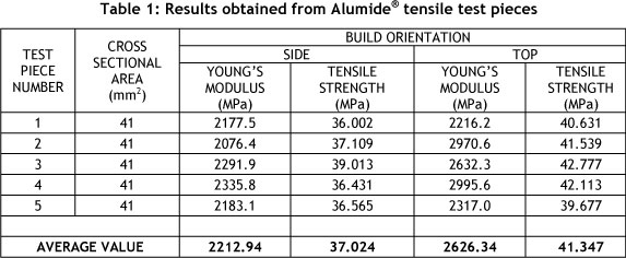
The values obtained for Young's modulus and tensile strength from this experiment are less than the values of 48 MPa (tensile strength) and 3.8 GPa (Young's modulus) for Alumide® provided by EOS [5]. A possible explanation for this deviation is that the supplier used different scanning build parameters during AM.
Further experiments will be done using different laser scanning parameters on test pieces (built with a build orientation from the top) to determine whether the mechanical properties can be improved any further. Test pieces will also be grown upright - i.e. with their length in the z-direction - as well as at an angle of 45°, to determine how these build orientations influence part strength.
4.2 Shelling of Alumide® inserts
Significant internal stresses are induced in Alumide® parts during the laser sintering process, with an increase in stress as the volume of the part increases. These stresses can result in warpage of the insert during the manufacturing stage. One way to overcome this problem is to shell the part. Shelling reduces the cost of the insert: less material is used and it can be produced in a shorter time.
During the injection moulding process, the Alumide® insert containing the mould cavity is subjected to high injection pressures and temperatures. The shelled Alumide® insert needs to be backfilled so that it will not collapse when subjected to the injection pressures of the molten polymer.
Criteria for a suitable backfilling material are:
• The backfilling material used must be able to withstand the mechanical stresses experienced during the injection moulding process.
- It must be quick and easy to use. A time-consuming or difficult process results in a labour intensive operation that will increase the cost of this operation.
- It must be able to withstand the injection pressures of the melted polymer during the injection moulding process (compression forces).
- It must be able to withstand the temperatures that occur during the injection moulding process.
- It must be easily machinable. Cooling channels, ejector pin holes, etc. need to be machined into the backfilling material.
- The material must be readily available in South Africa.
- It must be cost-effective.
- It must have a reasonably long pot life. This will assist when the material needs to be slowly poured into the back of the insert, to avoid forming voids.
- It must have good thermal conductivity to transfer heat away from the insert's surface.
After experimentation with different materials, we decided that Axon's EPO 4030 epoxy is the most suitable backfilling material.
This material does not show any significant temperature rise during the mixing process. Experiments were conducted on blocks with constant backfilling volume but varying wall thickness. Measurements were taken before the backfilling process, and these values were compared afterwards to determine whether there is an expansion force during the curing stage of the backfilling epoxy.
4.2.1 Deformation during the backfilling process
Experimental set up:
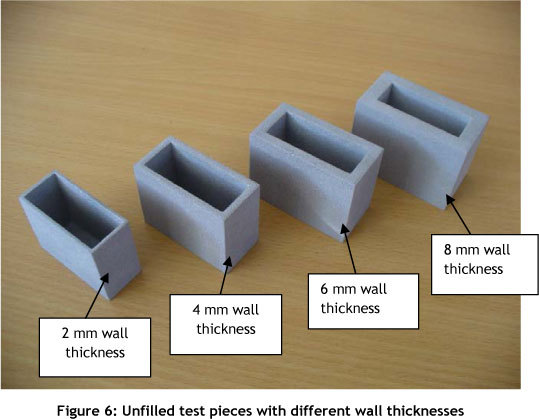
Experiments were conducted to determine a suitable shelling wall thickness for an Alumide® insert that will not deform when filled with EPO 4030 resin. Test pieces with the same cavity volume, but with varying wall thickness, were made. Figure 6 illustrates the unfilled test pieces with different wall thicknesses.
EPO 4030 resin was mixed according to the specifications in the manufacturer's data sheet. The mixing ratio is as follows:
- Resin: 100%
- Hardener: 10% of resin weight
- Aluminium granular filler: 55% of resin weight
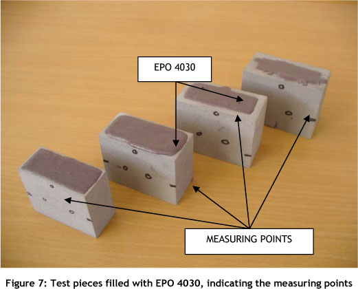
The mixture was slowly poured into the cavities to minimise the forming of air pockets.
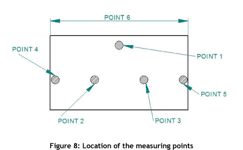
Measurements were taken on the test pieces before the cavities were filled with EPO 4030 resin. These measuring points were marked on the test pieces so that measurements could be taken at the same positions after the cavities were filled. Figure 7 illustrates the test pieces after filling, indicating the measuring points.
4.2.2 Accuracy results
The average deviation from the measurements for the different wall thickness test pieces, taken before they were filled, is summarised in Table 2. Figure 8 shows where the measurements were taken.
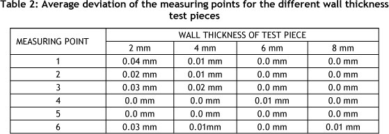
4.2.3 Conclusion
From Table 2, we can conclude that EPO 4030 does not significantly influence the dimensions of an Alumide® insert during the backfilling process. There are slight measurement deviations on the test pieces with two and four millimeter walls, while the deviation on thicker walls is so small as to be negligible. The wall thickness of a shelled Alumide® insert will be determined by the injection pressure of a polymer during the injection moulding process. The parameters of the cooling channels for conformal cooling of the Alumide® inserts can also affect the required wall thickness.
4.2.4 Homogeneity of backfilling medium
Test samples were produced by cutting through the test pieces and machining the surface of the samples flat to determine the distribution of the aluminium granulates through the cavity. Figure 9 shows that there is a uniform distribution of aluminium granulates from the base to the top of the insert.
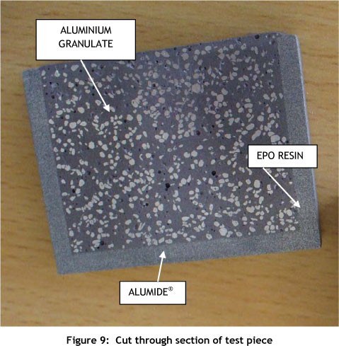
This distribution of aluminium granulates throughout the cavity is important, because it helps to dissipate heat from the cavity surface to the cooling channels and the rest of the mould bolster. Effective heat dissipation from the cavity surface increases the usable lifespan of the Alumide® insert.
Figure 10 shows a magnified image of an Alumide® insert filled with EPO resin. It shows that a 'solid' bonding between the EPO resin and the cavity walls of the Alumide® insert has been achieved. The irregular dark grey pockets on the image are the pockets of aluminium granulate that were removed during the cutting and milling process.
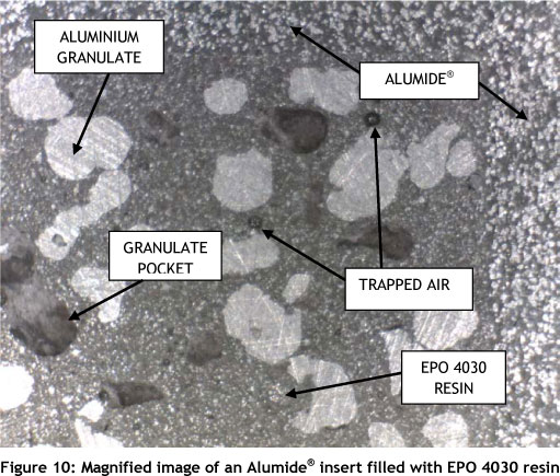
During the sectioning procedure, we determined that the EPO 4030 resin can be easily machined.
4.3 Accuracy of Alumide® inserts
The accuracy of the Alumide® manufactured inserts produced through the laser sintering process was determined using a Renishaw touch probe scanner with an achievable accuracy of 0.005 mm to 0.01mm. Figure 11 shows a press tool for a cranio-plate prototype. A titanium (Ti) plate will be pressed over the Alumide® insert in the USA, using hydro-forming technology. Aerosud, a South African aerospace company, will facilitate the testing of this Alumide® tool in the USA. The average deviation across the surface of the tool is -0.05 to 0.052 mm, compared to the original computer aided design (CAD) of the tool. This is within acceptable tolerances.
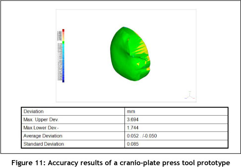
Figure 12 shows the design of the female part of a press tool that will be tested at the CUT to determine the spring-back in an aluminium plate when pressed between the two halves of the Alumide® tool. The deviation is also indicated in Figure 12, and shows that the average deviation is -0.063 to 0.107 mm.
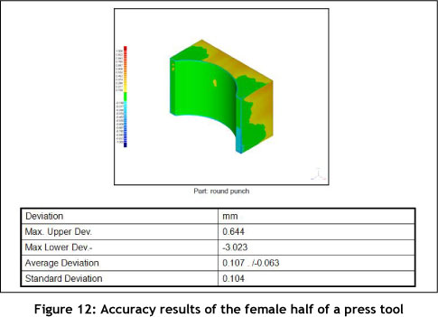
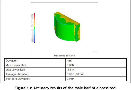
Figure 13 shows the design of the male part of the same press tool that will be tested at the CUT. The deviation is also indicated in Figure 13, and shows that the average deviation is -0.043 to 0.087 mm.
From these case studies, we can conclude that accuracy of up to 0.1 mm can be achieved with the sintering process of Alumide® inserts. These results confirm that Alumide® can be used as a medium for inserts in the IM process.
5. CASE STUDY
A client needs about ten thousand plastic wheels annually to produce toy wire cars. The wheels' design consists of complex geometries such as long and thin ribs. Two sets of wheels, one large and one small, were required. Each wheel needed a wheel cap. Four moulds had to be manufactured to achieve all of this.
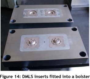
The DMLS process was the best option, given the complexity and the requirement that the production run be annual. It was also decided to manufacture the same insert geometries in the Alumide® material to compare the two processes. Inserts were produced through both techniques, with the DMLS inserts fitted into bolsters as shown in Figure 14.
The main concern is that the AM machine that produces the Alumide® inserts uses a layer thickness of 0.15 mm, while the machine that processes DMLS parts uses 0.02 mm layers. This results in the Alumide® inserts having a rougher surface finish; and problems may occur during the ejection process (the injection-moulded part may stick to the core). Hand finishing will be required inside the Alumide® inserts, and this can affect the accuracy of the moulded parts. Figure 15 shows all the cores and cavities necessary to complete the project, as well as the thin-shelling at the back of the Alumide® inserts. It also shows how extra provision was made around the area where the ejector pins operate.
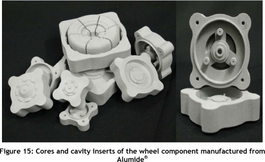
Figure 16 shows the deviation plot of the cavity design of a plastic tractor wheel compared with the actual Alumide® sintered insert. It shows that the average deviation is -0.070 to 0.105 mm, with 82% of the scanned points in the range -0.01 to 0.01 mm. The red areas on the image are where the touch probe could not reach due to the design of the probe.
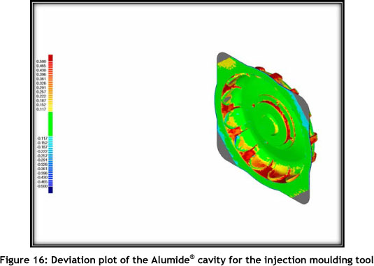
Figure 17 shows the deviation plot of the core design of a plastic tractor wheel compared with the actual Alumide® sintered insert. The average deviation is -0.070 to 0.105 mm, with 82% of the scanned points in the range -0.01 to 0.01 mm. The red areas again show where the touch probe could not reach.
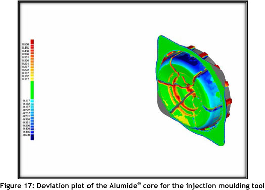
Table 3 shows the manufacturing time comparison of the DMLS and Alumide® inserts, while Table 4 shows the manufacturing cost comparison of the DMLS and Alumide® inserts.
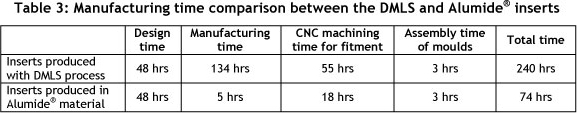
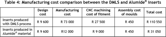
From the tables above, it is clear that research into laser sintered Alumide® inserts for the IM process is important, because these Alumide® inserts result in both a cost saving and a reduction in development time for a limited run production (100-2,000 parts). It is important to keep the cost and development time as low as possible in the new product development process. These limited run production quantities are large enough to test, and to get feedback from the market, before committing to manufacture conventional production tools. The quoted amount for conventional tooling for this project was approximately R 200 000.
6. CONCLUSION
This paper introduces Alumide® as an alternative material for producing moulds for the plastic injection moulding process. A successful thin-shelling strategy was developed for inserts manufactured in Alumide®, resulting in savings in cost and time. The thin-shelling also helped to minimise the deformation (warpage) of the inserts during manufacturing. The backfilling of the Alumide® inserts had no influence on the accuracy of the inserts, and it helped to improve their compression strength. The overall accuracy of the laser sintered Alumide® inserts was found to be acceptable when compared to the original CAD drawings. The case study showed significant cost and time savings when using Alumide® inserts compared to DMLS inserts. These findings justify further research into this material to qualify it as a suitable tooling material for limited run plastic injection moulding.
REFERENCES
[1] Aronson, R.B. It's not just RP anymore, retrieved from www.mmsonline.com. Accessed on 21 October 2009. [ Links ]
[2] Booysen, G.J. 2006. Bridge tooling through layered sintering of powder, Thesis (M Tech). Bloemfontein: Central University of Technology, Free State. [ Links ]
[3] Cleveland, B. Prototyping: Matching the method, retrieved from www.appliancedesign.com. Accessed 12 February 2010. [ Links ]
[4] De Beer, D., Booysen, G., Barnard, L. & Truscott, M. 2005. Rapid tooling in support of accelerated new product development, Assembly Automation, 25(4), 306-308. [ Links ]
[5] EOS e-Manufacturing Solutions. Alumide data sheets, retrieved from http://eos.materialdatacenter.com/eo/en. Accessed 10 January 2012. [ Links ]
[6] Gibson, I., Rosen, D.W. & Stucker, B. 2010. Additive manufacturing technologies rapid prototyping to direct digital manufacturing, Springer Science & Business Media. [ Links ]
[7] Hopkinson, N., Hague, R.J.M. & Dickens, P.M. 2006. Rapid manufacturing: An industrial revolution for the digital age, John Wiley & Sons Ltd. [ Links ]
[8] Kagan, G. High-performance prototyping at 3PAR, retrieved from www.timecompression.com. Accessed 7 January 2010. [ Links ]
[9] Noorani, R. 2006. Rapid prototyping principles and applications, John Wiley & Sons Ltd. [ Links ]
[10] Ogando, J. Rapid prototyping moves toward rapid tooling, retrieved from www.ptonline.com. Accessed 13 January 2010. [ Links ]
[11] Sands, T. 2001. The role of rapid immediate production tooling (IPT) in product development, Rapid Prototyping Casebook, Professional Engineering Publishing Limited. [ Links ]
# This article is an extended version of a paper presented at the 2011 RAPDASA conference.

