


Servicios Personalizados
Articulo
 Inglés (pdf)
 Articulo en XML
 Referencias del artículo
Indicadores

Links relacionados
-
 Citado por Google
 -
 Similares en Google
Compartir

 Permalink
South African Journal of Industrial Engineering
versión On-line ISSN 2224-7890
versión impresa ISSN 1012-277X
S. Afr. J. Ind. Eng. vol.23 no.2 Pretoria ene. 2012
GENERAL ARTICLES
Overview of work piece temperature measurement techniques for machining of Ti6Al4V#
P.J.T. ConradieI, *; G.A. OosthuizenII; N.F. TreurnichtIII; A. Al ShaalaneIV
IThe author was enrolled for an MScEng (Engineering Management) degree in the Department of Industrial Engineering, Stellenbosch University. Department of Industrial Engineering Stellenbosch University, South Africa. pconradie@sun.ac.za
IIDepartment of Industrial Engineering Stellenbosch University, South Africa. toosthuizen@uj.ac.za
IIIDepartment of Industrial Engineering Stellenbosch University, South Africa. nicotr@sun.ac.za
IVThe author was enrolled for a B.Eng (Industrial) degree in the Department of Industrial Engineering, Stellenbosch University. Department of Industrial Engineering Stellenbosch University, South Africa. 15143031@sun.ac.za
ABSTRACT
Ti6Al4V is one of the most widely used titanium alloys in aerospace applications, but its machining remains a challenge. Comprehensive research has been done in the past, mainly investigating tool failure of various materials. Less research has been done to investigate the thermal effect of machining on work piece quality, including fatigue performance. Temperature measurement is considered to be a key enabling technology. This study presents an overview of current temperature measurement techniques for machined and tool surfaces. Two categories of methods were investigated: slower contact, and faster optical methods. Optical fibre two colour pyrometry experiments are reported that demonstrate the technique's adequate response time. The infrared camera temperature measurement experiments synchronised temperature measurement with visual observation, aimed at mechanism analysis. The results corresponded with the literature.
OPSOMMING
Ti6Al4V is een van die mees gewilde lugvaart allooie, maar sy masjinering is 'n uitdaging. Bestaande navorsing dek beitelslytasie omvattend. Die termiese effek van masjinering op werkstuk integriteit, insluitend vermoeiingleeftyd, het egter veel minder dekking geniet. Temperatuurmeting wat in hierdie studie ondersoek word, word as 'n sleuteltegnologie beskou. Twee kategorië metodes is ondersoek, nl stadige kontakmetodes en optiese metodes met vinnige respons, wat die meting van oorgangsverskynsels moontlik maak. Eksperimentele werk wat beide optiese vesel tweekleurpirometrie en termiese kamera tegnieke insluit bewys die tegnieke as geskik vir die benodigde navorsing.
1. INTRODUCTION
Titanium alloys have found several niche applications where their unique properties justify the premium price of the metal. Ti6Al4V in particular is widely used in the aerospace sector. This acceptance is mainly driven by its strength-to-density ratio even at moderately elevated temperatures, and by its resistance to corrosion. Although these qualities define it as an outstanding material, they also constrain the machinability of titanium. Ti6Al4V combines an exceptionally low thermal conductivity, high chemical reactivity at the temperatures encountered in contemporary high productivity machining, and a low modulus of elasticity [1]. So the cutting speeds (vc) are limited to relatively low values [2]. When Ti6Al4V is milled, high temperatures at the cutting tool/work piece interface and prominent friction phenomena are encountered. This causes tool wear and finished work surface sensitivity for cutting parameters, characteristic of the 'difficult to machine' class of materials. Exposure of the workpiece surface to normal cutting conditions for other metals leads to excessive temperatures during machining that could result in undesirable micro-structural transformation and thus in compromising fatigue performance of the component. The cause of fatal civil aviation accidents has been traced back to fatigue nucleation sites primarily caused by machining-induced micro-structural transformation [3].
Undesirable micro-structural change of titanium alloys is relatively unknown outside the technology cores of the major airframe and engine manufacturers, placing a heavy quality control burden on aerospace systems houses, and limiting competitive supplier participation. Ultimately it presents a very real risk factor in aerospace manufacture [4]. In civil aviation, scheduled inspections to detect early fatigue crack are extensive. Current methods rely on human detection, and have been proved to be prone to failure. Undesirable micro-structural change compromising fatigue performance therefore needs to be reliably eliminated, by design, from the manufacturing process. This field of study is rather complex, and requires further comprehensive development of supportive measurement and analysis possibilities [3].
The entire spectrum of aerospace players - from machining suppliers to systems integrators - could therefore translate further research in this field into enhanced component reliability and ultimately flight safety. Increased accuracy and high time-domain resolution temperature measurement methods are therefore a knowledge frontier that contributes to the elimination of fatigue-related micro-structural change by process design [1]. With increasing command of this knowledge domain, responsible maximising of the cutting speed productivity improvement could be effected.
Temperature measurement can be divided into two main categories: conduction and radiation. Using thermocouples is the most frequently-used technique, and is discussed here among the conduction techniques. Radiation measurement consists of infrared and optical thermocouple techniques. This investigation discusses a number of temperature measurement techniques, and reports sample experimental results from optical fibre pyrometry and infrared photography. The goal is to illustrate relatively recent experimental temperature measurement techniques.
2. TEMPERATURE MEASUREMENT TECHNIQUES USED IN MACHINING
A variety of methods are available for temperature measurement during machining. As most techniques require a dry environment, it is still a major challenge to measure the temperature under cooled and lubricated conditions. An overview of the measurement methods is given, together with a discussion of key strengths and constraints.
2.1 Conduction
Transfer of energy from the more energetic particles of a body to the neighbouring, less energetic particles takes place by means of the interactions between the particles. This energy transfer mechanism is referred to as conduction [5]. Figure 1 shows measurement methods that rely on heat conduction from the measured body to the sensor unit.
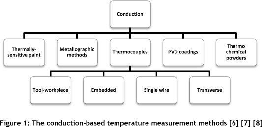
Conduction temperature measurement methods use instrumentation that measures the temperature difference between two points that are in direct contact with each other. Heat will be transferred within the material, from a location that has a higher energy level to one that is lower, thereby yielding a transfer value to give a temperature measurement.
2.1.1 Thermally-sensitive paints
This technique uses the principle of a chemical reaction that takes place at a specific temperature to change colour [9]. Approximate values of the peak temperatures to which the cutting tools and/or workpieces were exposed are indicated. The paint is applied before the experiment to the areas of interest [9]. A split-cutting tool setup is the advised practice [10]. Practical application of a split setup is that the cutting tool is configured into symmetrical halves. The paint is applied to one side and the tool is reassembled. Characteristics of the thermally-sensitive paint technique are listed in Table 1.
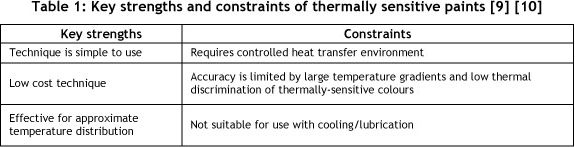
The most prominent factor is that the technique is uncomplicated and inexpensive to achieve an overview. It is suitable for dry conditions where heat input is controlled.
2.1.2 Metallographic methods
The micro-structure of a metallic alloy is typically characteristic of its thermal history [9]. Metallographic methods utilise this principle: the micro-structure can be correlated with the temperature to which the material has been exposed. The micro-structure of the experimental sample is compared with reference micro-structures, and the temperature is determined. In a similar way the hardness - using a micro-hardness test - is compared with reference information [9]. By logging the micro-structure and hardness values at desired points in a material sample, temperature isotherms can be plotted and the temperature history can be determined. The strengths and constraints are presented in Table 2.
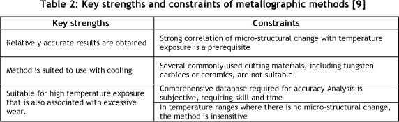
This method is rather practical for machining investigative work, as it can be used with cooling that has become an essential part of modern machining practice. To get good discrimination with this technique, it is necessary to operate at high temperatures, which yields excessive tool wear that is not representative of production conditions. This diminishes the usefulness and attractiveness of the technique.
2.1.3 Thermocouples
When there is a temperature gradient along the length of an electrical conductor, a phenomenon known as the Seebeck effect occurs [11]. A current is induced thermally, causing a voltage drop. This is the case for any conducting material experiencing a thermal gradient [12]. This gradient can exist across two (hot and cold) junctions, resulting in an electromotive force (emf). The emf is characteristic for the conductor materials used, and is also dependent upon the temperatures of the junctions [13]. In this way a highly repeatable temperature measurement device is constructed, commonly known as a thermocouple. In Table 3 the ranges of eight standard thermocouples are shown.
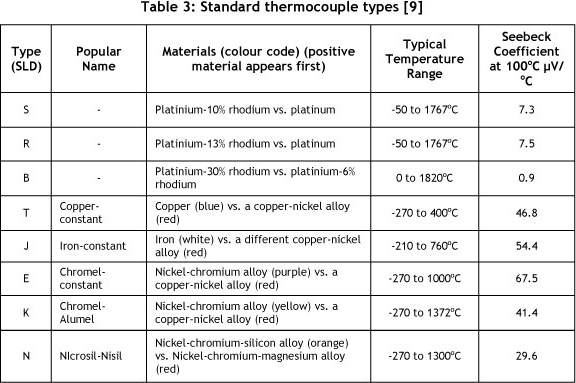
Thermocouples containing noble metals such as platinum and platinum-rhodium combinations are referred to as 'noble metal thermocouples', and are designated as Type B, R, and S. Other types are referred to as 'metal thermocouples', and are designated as Types E, J, K, and T [9], which can be chosen considering the temperature range.
2.1.3.1 Embedded thermocouples
When a thermocouple is inserted into an appropriate sized hole in the workpiece material, it is referred to as an 'embedded thermocouple'. The thermocouples are usually mounted perpendicularly and rather close to the surface where the temperature needs to be measured. Figure 2 shows the application of embedded thermocouples for milling.
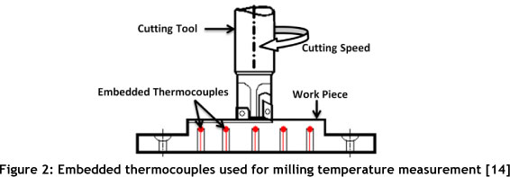
Because the sensing point is below the surface, surface temperatures cannot be measured directly. Used in conjunction with heat transfer models, temperature prediction is feasible [11]. A constraint associated with thermocouples is that heat transfer to the sensor causes a time lag in the temperature response. For the same reason, calibration of embedded thermocouples at high temperatures is problematic [11]. The hole is typically filled with thermally conductive cement with similar thermal properties to those of the work material, to displace all air. Thermocouple holes below the work surface could influence the heat conduction away from the heated surface, compromising accuracy. Nevertheless it is a proven and simple technique to use. The strengths and constraints are shown in Table 4.
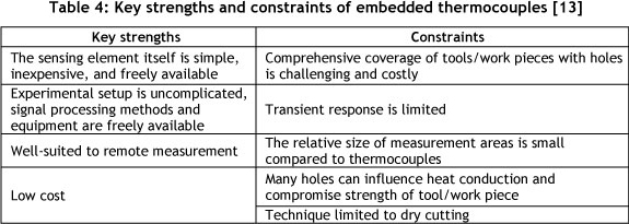
An embedded thermocouple is an effective measuring device that is simple in construction, operation, and signal processing. Constraints such as the cost of drilling holes could lead to an alteration of the heat conduction rate through the material.
2.1.3.2 Tool/work piece thermocouple
In machining, two bodies engaged in relative motion - the cutting tool and the work piece -can be configured as the two elements of a thermocouple in order to measure temperature. This is known as the Shore-Gottwein-Herbert technique [9]. A particular strength of the technique is to investigate the temperature effects of varying cutting parameters such as feed rate (fz) and cutting speed (vc). A constraint of the method is that the accuracy of measured values is not absolute, limiting the use to comparisons. As the tool and work piece are dissimilar metals in contact during cutting, a thermo-electric emf can be measured. The hot junction is the cutting zone itself; an electrical connection to a cold part of the tool and work piece forms the cold junction. A necessary modification to a standard machine tool is that the work piece and tool need to be electrically insulated from the machine tool [15]. The concept is illustrated in Figure 3.
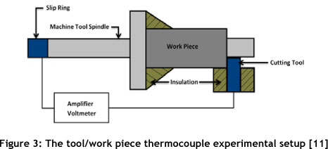
Traditionally tool/work piece thermocouple applications are used to determine an average temperature in the cutting zone, not to characterise thermal gradients associated with material non-homogeneities [12]. In the literature, however, several numerical and theoretical analyses of the dynamic thermocouple are reported in an attempt to extend its use and determine the effect of variable temperatures on the tool/work piece interface, with mixed success [12]. The method has been shown to be useful for obtaining qualitative- information and trends of interface temperatures, as well as their correlations with tool wear [12]. The key strengths and constraints are presented in Table 5
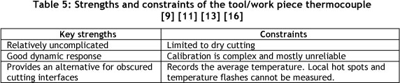
Simplicity of use, the ability to measure interfaces that are inaccessible by means of standard techniques, and good dynamic response define its applications. Calibration is challenging if not impossible, and only average temperature is recorded in dry conditions.
2.1.3.3 Single wire thermocouple
The term 'single wire thermocouple' is used where a part of the work piece is cut into two sections across the line of cutting. Additionally, a thin insulated wire is mounted through the work piece. The principle of operation is illustrated in Figure 4.
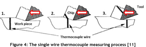
As the end of the conductor (thin wire) makes electrical contact with the work piece surface, a signal is generated. The thin wire is cut during milling, exposing it and forming a thermocouple between the wire and the cutting tool [15]. Signal duration is only during electrical contact with the wire, and thus extremely short. A high sampling rate is used to record the signal during the short measurement interval [11]. This technique is similar to using an embedded thermocouple, sharing most of its strengths and constraints. Those specific to this method are listed in Table 6.
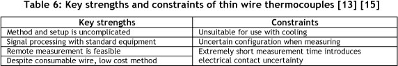
Using the thin wire thermocouple is straightforward, and signal processing is done with standard equipment. An entire setup can be acquired at low cost, and the usual- requirement for remote measurement is easily met. Short contact times and electrical conduction problems require several repetitions and variance analysis. Fluid cooling amplifies inaccuracies and is infeasible.
2.1.3.4 Transverse thermocouple
Transverse thermocouples were intended to investigate tool temperature distributions on the end-, clearance-, and rake face of the tool within the chip-tool interface area in three dimensions [9]. The method is related to the tool/work piece thermocouple, with the difference that the contact point between the chip and tool changes continuously as the cutting progresses [9]. A diagrammatic presentation of the transverse thermocouple setup is shown in Figure 5. The tool material and a sharp probe of another material constitute the thermo-electric junction. As the probe moves, a continuous temperature distribution relative to a specific edge is recorded [9].
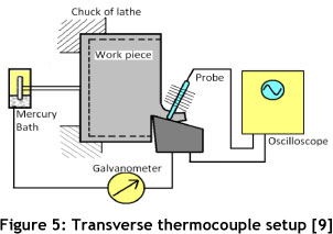
The probe can therefore continuously transverse on the tool surface where the temperature is of interest. The key strengths and constraints are listed in Table 7.
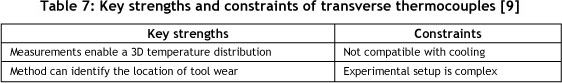
The unique result of this method is a 3D temperature distribution that can identify the location of tool wear. The method requires a complex set-up and is unsuitable for cooling.
2.1.4 PVD coatings
With this method, measurement is by a physical vapour deposition (PVD) coating that is deposited on a split-tool in an aqueous solution. When temperature thresholds are exceeded, they are recorded by observably melted coatings. In this way the internal temperature of a solid body during milling can be determined. The temperature detection coating consists of several materials with different melting points that are physically-vapour-deposited on the cutting tool's split surface [17]. Ranges of different PVD coatings, along with the temperatures at which they melt, are listed in Table 8.

As each film material melts at a different temperature, an image of the spatial distribution of temperature near the cutting edge is recorded. Using calibration tests, the exact temperature can be determined at the boundaries between the melted and un-melted films [17]. Figure 6 shows boundary images of machining experiments [9] with the PVD material tellurium.
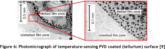
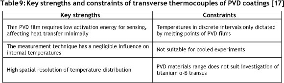
The boundary between the melted and un-melted regions (shown in Figure 6) is the isotherm of 723K - the melting temperature of tellurium, as indicated in Table 8. The key strengths and constraints of transverse thermocouples are shown in Table 9.
The main strength of PVD coatings is that measurement has a minimal influence on heat transfer into the work piece, thus negligibly affecting internal temperatures. Micrographic results offer clear binary interpretation, leading to reliable detection of temperature distributions. Although the contours are accurately mapped on the spatial domain, the PVD materials limit the method to discrete sensing points on the temperature scale, resulting in a rather limited resolution, stepwise detection method. The PVD film technique is not suitable for use with cooling, as cooling damages the PVD coating.
2.1.5 Thermo-chemical powders
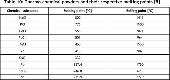
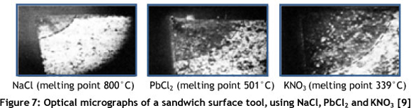
Similarly to the use of PVD coatings, temperature sensing is achieved by visual observation of the melting of the powder. Using this method, the cutting tool is configured in two parts with a symmetrical interface. During assembly a layer of powder is applied to the interface. The temperature distribution is determined by repeating the experiments using powders with different melting points, one at a time. Table 10 lists frequently-used powders with their respective melting and boiling points [15].
As the results are obtained for one type of powder at a time, they are combined by superimposing the boundary lines of the different tests to determine the temperature isotherms. Figure 7 illustrates the melting boundaries of three different powders (NaCl, PbCl2 and KNO3) with a carbide tool.
During microscopic analysis a clear visual distinction can be made between the melted and un-melted zones, enhancing repeatability. The main strengths and constraints of the thermo-chemical powders are listed in Table 11.
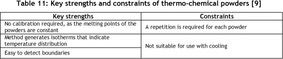
The use of chemical powders for temperature detection is an easy repeatable method, due to the clear visual change and constant melting points of the powders. A constraint is the repetitions for each temperature to be sensed. High pressure cooling is not usable, as the powder would be removed from the interface.
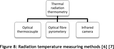
2.2 Thermal radiation
Thermal radiation is the energy that is electromagnetically emitted by matter above the absolute zero temperature [5]. Figure 8 illustrates the methods that were explored in this study.
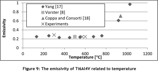
The thermal radiation of an object is determined by its emissivity and temperature. Emissivity (ε) is a material property, and is defined as the ratio of the radiation from a body- to the radiation of a black body at the same temperature. It is common to determine emissivity using the temperature of the object determined by the thermal radiation method, together with an absolute temperature measurement of the object - such as by thermocouple. The accuracy of thermal radiation temperature measurements depends directly on the accuracy of the emissivity. Emissivity is variable with temperature and the presence of an oxide layer, requiring extreme care when interpreting instrument-based readings. This places radiation thermometry for machining in the scientific rather than industrial domain.
In radiation thermometry, emission in the infrared band, defined as from the edge of visible red light at 0.74 µτη to 300 Mm, is used (frequency 1 to 400 TeraHz).
2.2.1 Optical thermocouple
An optical fibre is placed beneath the work piece so that a change can be detected in the emitted wavelength. The Bragg gratings are made by illuminating the core of an appropriate optical fibre with a spatially-varying pattern of intense ultraviolet light [11]. Short wavelength UV photons have enough energy to break the extremely stable silicon-oxygen bonds, so that the structure of the optical fibre is damaged, leading to a slightly increased refractive index. This adapted fibre can then operate as a wavelength selective mirror [11]. This reflective wavelength is affected by any variation in the mechanical or physical properties of the grating region. A change in temperature will lead to a change in the effective refractive index as a result of the thermo-optic effect. To implement this technique on a work piece, it must be placed on the optical tube - or the optical tube must be placed in a sandwich between the piece that will be cut and a backing apparatus [11]. The strengths and constraints are summarised in Table 12.

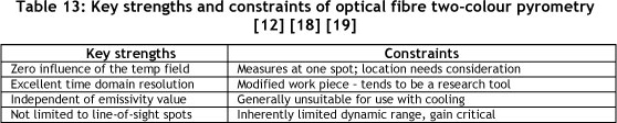
2.2.2 Optical fibre pyrometry
Using a typical Ø0.65mm optical fibre, temperatures can be sensed in otherwise inaccessible locations. The optical fibre facilitates remote sensing, allowing the sensors to be physically larger. Cooled detectors can be used, enhancing sensitivity and ultimately time domain response. Two-colour pyrometry uses detectors with wavelengths close together. In calculating the temperature, the ratio between the emissivities is used, eliminating emissivity as a dependent parameter. The key strengths and constraints are summarised in Table 12.
The method is extremely fast, in an accessibility class of its own, and analysis can be complex.
2.2.3 Infrared cameras
Infrared (IR) light is focused with a special lens, and scanned by a phased array of IR detector elements, creating a thermogram. This is translated into electric impulses that are sent to a signal-processing unit, where the information is converted into data for the display. It is possible to acquire spot temperatures by selecting a position and getting a value for that point [11]. Table 14 summarises the key strengths [16] and the constraints [11] using an infrared camera to measure the temperature.

Thermal cameras are highly developed and easy to use. They do not influence the temperature field, and cooled detector types have good time domain resolution. Measurement requires a clear line of sight. Flying chips and coolants will require special attention. Since the camera is dependent on an accurate emissivity value, all sources of variance need to be considered and covered by calibrations.
3. EVALUATION OF THE TEMPERATURE MEASUREMENT TECHNIQUES
The strengths and constraints of each technique tend to define some as more suitable for specific applications. Some of these techniques are suitable for a broad range of applications, while certain requirements - such as cooling, which is an essential part of industrial machining practice - exclude almost all techniques. The requirement for high time domain resolution is met by some techniques, but is a serious constraint with others. The comparison is detailed in Table 15.
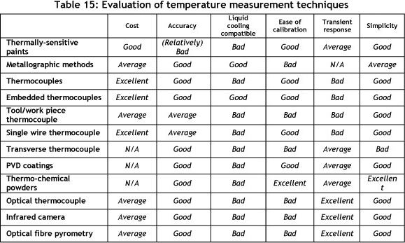
Metallographic methods and embedded thermocouples have been used successfully in cooled applications. Some of the other techniques may also be used in cooled applications with a specialised setup. For example, using reverse side IR radiation, thermal radiation techniques can be used to obtain measurements with cooling. Some techniques have a favourable assessment on most criteria, and are therefore suitable for machining applications. The thermocouple is one such example. It is robust, simple to use, and sufficiently accurate.
Both infrared photography and optical fibre pyrometry are relatively new technologies, and have the potential to measure the temperatures indicative of heat flow in the work piece during machining operations. These techniques are relatively accurate and have fast response times. Both are relatively simple to use, and lubrication can be used with custom experimental setups. Therefore, examples of how these methods can be applied experimentally are included, as well as illustrative results.
4. EXPERIMENTAL SETUP AND RESULTS
4.1 Emissivity determination
An emissivity value for titanium relative to temperature (cutting speed) for Ti6Al4V was determined. The temperature of a sample in a furnace was simultaneously determined with infrared thermometry (Raytek MX-4+) and a thermocouple. The experimental results and those from the literature are shown in Figure 9. Avoiding false oxidation-based emissivity values at elevated temperatures proved to be impossible without a vacuum or inert gas atmosphere.
4.2 Optical fibre two-colour pyrometry experiment
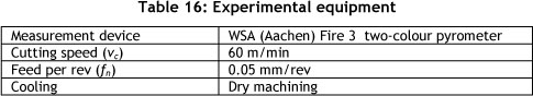
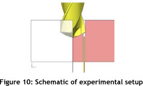
The aim of the experiment is to study drill tip [21] during drilling of TÍ6A14V. Table 16 details the equipment and the parameters setup uses a vertical spindle with the optical fibre in a sub-1 mm pilot hole in the work piece, as shown in Figure 10.
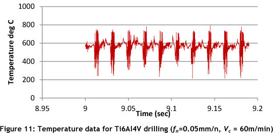
With two-colour pyrometry the temperature is calculated using the ratio of emissivities at two closely-spaced wavelengths, making the measurement independent of the emissivity value. Division by a signal strength related value approaching zero yields unstable temperature values that could approach infinity. Unstable values result if low signals - for this equipment, lower than 200 deg C - are measured.
In Figure 11 the drill tip temperatures can be identified as the flank faces of the drill pass over the optical fibre. Each flank face is followed by unstable data that represents the passing of the chip removal flute over the fibre. In these unstable data zones, temperatures- are below the detection threshold of the equipment, and the results are due to division by a small number - typical for two-colour pyrometry. As the temperature of the drill face can be determined to a resolution better than a data point per degree of rotation, the method can detect the influence of the effect of individual cutting edges on the heat balance at the cutting edge.
4.3 Thermal camera experiment
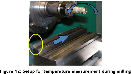
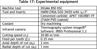
The aim of the experiment is to study 2D chip formation and temperature measurement during milling of Ti6Al4V. Table 17 details the equipment and the parameters used. The setup, consisting of a horizontal spindle over the thin (ap=2mm) work piece, creates a pure orthogonal cutting condition to fulfil the 2D requirement.
The rotation angle of the tool and the formation of the chip could be related to visual observations and the temperature measurements. As illustrated in Figure 13, there is a rise- in temperature as the cutting speed (vc) increases. The work piece volume, which increases in temperature, enlarges with an increase in cutting speed.
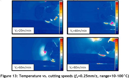
In Figure 13 the highest temperatures (in the range 10-100°C) occur at the cutting edge of the tool and also at the chip-tool interface. Due to titanium's low thermal conductivity, the high temperature does not penetrate deep into the machined material, as predicted by theory, since most of the heat is carried away by the Ti6Al4V chips [11], or penetrates into the cutting tool edge. Figure 14 illustrates the maximum temperature for cutting speeds measured with a higher selected range (=600-850°C).
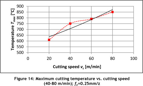
The results indicate an increase in temperature with cutting speed. Using the thermal camera, temperature information related to a range of cutting conditions - speed, feed, depth of cut, and edge geometry - can be obtained. The quantitative temperature information obtained with this experimental method is clearly suitable for use in modelling the micro-structural change in titanium.
5. CONCLUSION
Temperature measurement techniques were studied and evaluated. The response time of contact methods was found to be to relatively slow. Optical IR methods have the advantage of fast response, allowing the capture of intermittent heat generation as necessary during milling and drilling. The two-colour pyrometer experiments showed that the thermal- environment at the cutting tool's tip can be studied at a resolution of 1 data point per degree of rotation. The infrared camera temperature measurement experiments were conducted with a special setup in order to have a good visual of the temperature distribution. The maximum cutting temperature increases with an increase in cutting speed. Due to Ti6Al4V's low thermal conductivity, the heat is concentrated in a small area around the cutting edge. The combined effect of the concentrated temperature at the tool edge, the serrated chip formation, and low modulus of elasticity causes rapid tool wear. With the thermal camera, underlying mechanisms can be studied by relating visual images to spatial temperature distributions.
With this overview it can be concluded that a range of temperature measurement methods is available, ranging from quick and easy approximate methods to accurate, fast response methods.
REFERENCES
[1] Dimitrov, D. et al. 2010. High performance machining of selected titanium alloys for aerospace applications, ICMC, Chemnitz, Germany, pp.503-523. [ Links ]
[2] Oosthuizen, G., Akdogan, G. & Treurnicht, N. 2011. The performance of PCD tools in highspeed milling of Ti6Al4V, International Journal of Manufacturing Technology, vol.52, pp. 929935. [ Links ]
[3] Oosthuizen, G.A. 2010. Wear characterisation in milling of Ti6Al4V - A wear map approach, Stellenbosch, South Africa, PhD dissertation. [ Links ]
[4] Oosthuizen, G., Akdogan, G. & Treurnicht, N. 2010. Performance enhancement in the milling of Ti6Al4V, SAIIE 2010, Glenburn, Gauteng, pp.172-185. [ Links ]
[5] Cengel, Y.A. 2006. Heat and mass transfer. New York: McGraw-Hill. [ Links ]
[6] Sales, W.F., Guimaraes, G., Machado, A.R. & Ezugwu, E.O. 2002. Cooling ability of cutting fluids and measurement of the chip-tool interface temperatures, Industrial Lubrication and Tribology, pp.57-68. [ Links ]
[7] Potdar, Y.K. & Zehnder, A.T. 2004. Temperature and deformation measurements in transient metal cutting, Society for Experimental Mechanics, pp.1-9. [ Links ]
[8] Vorster, J.V.Z. 2010. Temperature measurement of titanium during milling, Stellenbosch. [ Links ]
[9] Komanduri, K. & Hou, Z.B. 2001. A review of the experimental techniques for the measurement of heat and temperatures generated in some manufacturing processes and tribology, Tribology International, pp.653-682. [ Links ]
[10] Arndt, G. & Brown, R.H. 1966. On the temperature distribution in orthagonal machining, International Journal of Machine Tool Design & Research, pp.39-53. [ Links ]
[11] Longbottom, J.M. & Lanham, J.D. 2005. Cutting temperature measurement while machining - A review, Aircraft Engineering and Aerospace Technology, pp.122-130. [ Links ]
[12] Davies, M.A., Ueda, T., M'Saoubi, R. Mullany, B. & Cooke, A.L. 2007. On the measurement of temperature in material removal processes, Annals of the CIRP, Vol.56, No.2, 581-604. [ Links ]
[13] Sutter, G., Faure, L., Molinari, A., Ranc, N. & Pina, V. 2003. An experimental technique for the measurement of temperature fields for the orthogonal cutting in high speed machining, International Journal of Machine Tools & Manufacture, 671-678. [ Links ]
[14] Rahman, M., Senthil, K.A. & Choudhury, M.R. 2000. Identification of effective zones for high pressure coolant in milling, Annals of the CIRP, 47-52. [ Links ]
[15] Da Silva, M.B. & Wallbank, J. 1999. Cutting temperature: Prediction and measurement methods - a review, Journal of Materials Processing Technology, 195-202. [ Links ]
[16] O'Sullivan, D. & Cotterell, M. 2001. Temperature measurement in single point turning, Journal of Materials Processing Technology, 301-308. [ Links ]
[17] Yang, J., Sun, S., Brandt, M. & Yan, W. 2010. Experimental investigation and 3D finite element prediction of the heat affected zone during laser assisted machining of Ti6Al4V alloy, Journal of Materials Processing Technology, 210 (1), 2215-2222. [ Links ]
[18] Muller, B. & Renz, U. 2001. Development of a fast fiber optic two color pyrometer for the temperature measurement of surfaces with varying emissivities, Review of Scientific Instruments, 72 (8), 3366-3374. [ Links ]
[19] Ueda, T., Sato, M., Hosokawa, A. & Ozawa, M. 2008. Development of infrared radiation pyrometer with optical fibres - Two colour pyrometer with non-contact fibre coupler, Annals of the CIRP, 57 (2), 69-72. [ Links ]
[20] Kato, T. & Fujii, H. 2004. Temperature measurement in a solid body heated by laser beam, International Journal of Machine Tools & Manufacture, 927-931. [ Links ]
[21] Coppa, P. & Consorti, A. 2005. Normal emissivity of sample surrounded by surfaces at diverse temperatures, Measurement, 38 (1), 124-131. http://sajie.journals.ac.za [ Links ]
* Corresponding author.
# This article is an extended version of a paper presented at the 2011 ISEM conference.

