


Services on Demand
Article
 English (pdf)
 Article in xml format
 Article references
Indicators

Related links
-
 Cited by Google
 -
 Similars in Google
Share

 Permalink
SA Journal of Radiology
On-line version ISSN 2078-6778
Print version ISSN 1027-202X
S. Afr. J. radiol. (Online) vol.23 n.1 Johannesburg 2019
http://dx.doi.org/10.4102/sajr.v23i1.1730
ORIGINAL RESEARCH
Chest radiographs of cardiac devices (Part 1): Cardiovascular implantable electronic devices, cardiac valve prostheses and Amplatzer occluder devices
Rishi P. Mathew; Timothy Alexander; Vimal Patel; Gavin Low
Department of Radiology and Diagnostic Imaging, Faculty of Medicine and Dentistry, University of Alberta, Edmonton, Canada
ABSTRACT
Several new innovative cardiac devices have been created over the last few decades. Chest radiographs (CXRs) are the most common imaging investigations undertaken because of their value in evaluating the cardiorespiratory system. It is important for the interpreting radiologist to not only identify these iatrogenic objects but also to assess for their accurate placement, as well as for any complications related to their placement, which may be seen either on the immediate post-procedural CXR or on a follow-up CXR.
Keywords: Chest radiographs; pacemaker; implanted cardioverter defibrillators; cardiac resynchronisation therapy; implantable loop recorder; valve replacement; transcatheter valve replacement; amplatzer septal occluder; amplatzer ductal occluder.
Introduction
Over the last few decades, several new innovative cardiac medical devices have been created. Almost all of the patients with implanted cardiac devices such as pacemakers, implantable cardioverter defibrillators (ICDs), cardiac resynchronisation therapy (CRT) devices, implantable loop recorders (ILR) and cardiac prosthetic valves undergo chest radiographs (CXRs) on a regular basis. Therefore, it is not uncommon for the resident, radiologist, intensivist or physician to be presented with a conundrum of CXRs having a variety of these devices on a day-to-day basis. Chest radiographs are the initial modality for evaluating the device location and its integrity after implantation and for diagnosis of complications and malfunction.1 The intention of this article is to inform the readers about these cardiac devices, their indications, their proper position on CXRs and commonly associated complications.
Cardiovascular implantable electronic devices
Cardiovascular implantable electronic devices (CIEDs) include implantable cardiac pacemakers, ICDs, CRT devices (also known as biventricular devices) and implantable cardiac monitors. In 2012 alone, at least 3 million patients were implanted with CIEDs.2 In the United States, approximately 100 000 ICDs and 300 000 pacemakers are implanted annually,3 while in the UK, the 10-year average growth rate for pacemakers and ICDs is 4.7% and 15%, respectively.4 It is important to understand the basic functions and differences between various CIEDs, as well as to recognise them on a radiograph.
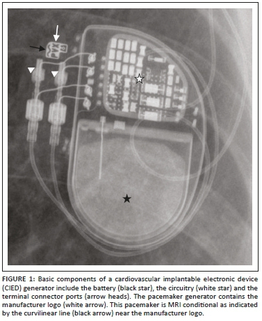
The CIED is composed of two main components: the pulse generator encased in titanium and the pacemaker or ICD lead(s). The pulse generator (Figure 1) comprises the circuitry, a lithium battery and the connector port. The CIED lead has five major parts: a conductor, insulation (silicone rubber or polyurethane), electrode(s), a fixing mechanism and a terminal connector pin. Proximally the leads are connected to the generator by the terminal connector by means of a connector block.5 Lead tips can be fixed actively or passively. Leads placed passively have radiolucent 'tines' at their end that anchor the lead tips in position. With time, the myocardium surrounding the lead tip undergoes fibrosis, further securing the lead tip in place. Active fixation leads have a retractable screw at its end which is deployed when the lead is placed in position. Specific situations where active fixation is used include right ventricular (RV) leads in the outflow tract and in situations where the right atrial (RA) leads must be secured to the tissue for stability. Active fixation leads are more commonly used in younger patients as it can be extracted much easier than passive fixation leads.6
Pacemakers
A pacemaker is a medical device that regulates the heart rate by electrical impulses delivered through electrodes to the heart muscles. The primary aim of this device is to maintain an adequate heart rate so as to not fall below a certain limit (mostly 60 beats/min), either because of a dysfunction of the heart's natural pacemaker or because of a block in the electrical conduction system of the heart.4,5 Pacemakers can be temporary or permanent.
Temporary pacemakers
These pacemakers are meant for short-term use during hospitalisation such as for bradydysrhythmia following a heart attack, cardiac surgery or drug overdose. The main equipment of the temporary pacemaker (the external pacemaker generator) is located outside the body and may be attached to the patient's skin by a tape or body by a belt.6 The method of choice for temporary pacing in the intensive care unit (ICU) is transvenous pacing. Temporary epicardial pacing is the most common choice following cardiac surgery and for permanent pacing in children. Other alternatives include transthoracic, transesophageal or transcutaneous pacing routes.7,8
Permanent transvenous pacemakers
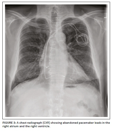
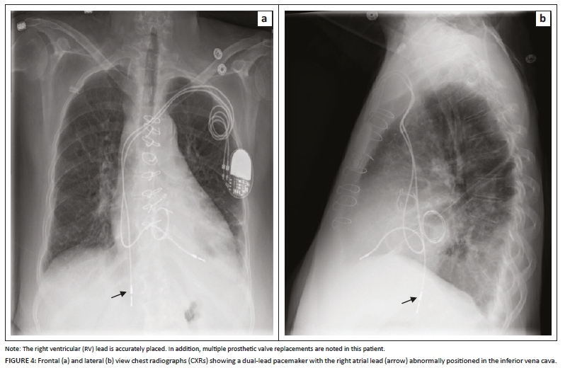
These pacemakers are meant for chronic cardiac rhythm dysfunction with abnormally low heart rate and, in general, have a sensing (and/or pacing) lead in the right atrium and a pacing (and/or sensing) lead in the right ventricle. Permanent pacemakers can be single-chamber pacemakers (usually with a single lead in the apex of the right ventricle especially for patients with atrial fibrillation; however, a single lead may be seen in the atrium for patients with sick sinus syndrome), dual-chamber pacemakers (with two leads, one in the RA appendage and the second in the RV apex) (Figure 2a and b) or biventricular pacemakers also known as CRT devices that have been developed for treating severe congestive heart failure. The CRT device will be discussed later separately.1,8,9 The leads of the permanent pacemakers are inserted using a transvenous route usually through the left or right subclavian vein or rarely through the internal jugular, axillary or femoral vein. The pulse generator is implanted into the subcutaneous layer of chest below the clavicle and above the pectoral muscle (prepectoral fascia). Rarely, the pulse generator may be placed under the skin of the abdomen, inframammary site in women for cosmetic reasons and right infraclavicular site for the left handed.4,10 During the insertion of a pacemaker, the standard procedure is a fluoroscopic evaluation of the positioning of the pacemaker electrodes, followed up by a CXR post insertion. Chest radiographs are also useful for identifying abandoned pacemaker leads (Figure 3) and complications (Figure 4a and b) which have been elaborated on in detail in Table 1.4,10
Recently, leadless pacemaker systems have been developed as a minimally invasive option for patients requiring single-chamber pacemaker placement. The two RV leadless pacemaker systems currently available for clinical use are the Nanostim™ Leadless Pacemaker System (LPS) (St. Jude Medical) and the Micra™ Transcatheter Pacing System (TPS) (Medtronic), both of which are inserted via femoral venous access and implanted directly into the RV wall. On CXRs, these devices appear as a linear radiopaque material implanted into the RV wall. Potential complications that can be identified on CXRs include device dislodgment and cardiac perforation.11
Implanted cardioverter defibrillators
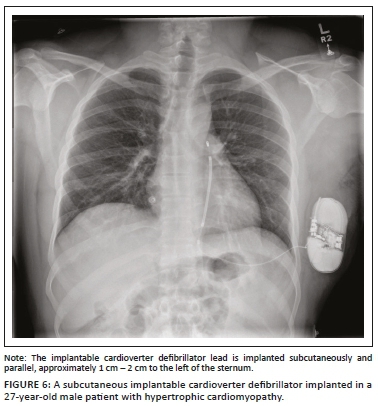
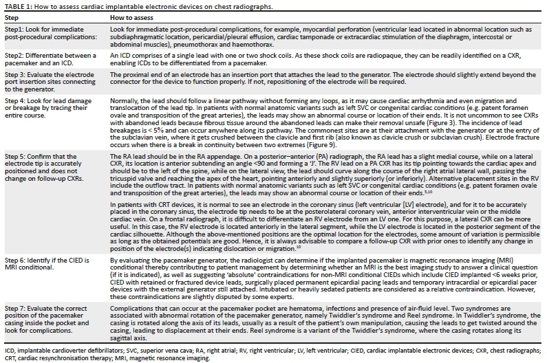
An ICD is a medical device capable of producing a large amount of electrical energy in a single output, used to defibrillate the heart. It is mainly used in patients with tachydysrhythmias (e.g. ventricular tachycardia or ventricular fibrillation) and for preventing cardiac arrest. An ICD usually comprises of a single lead with one or two shock coils. A shock coil has a relatively thick electrode to reduce the risk of damage to the myocardium from the defibrillating shock. When a two-shock-coil device is placed accurately, one shock coil will be terminating at the brachiocephalic vein-SVC junction and the second coil in the RV (Figure 5a and b). As these shock coils are radiopaque, they can be readily identified on a CXR, enabling ICDs to be differentiated from a pacemaker.5,10,12 A newer approach is to place a subcutaneous ICD lead to the left of the sternum (Figure 6).
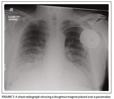
During surgery in the operating room, a CIED can sense an external magnetic interference (EMI) that can affect its pacing function. The source of the EMI may include electrocautery, external defibrillation, radio frequency ablation (RFA) and dental instruments. A cardiac device magnet (Figure 7) may be used temporarily by placing it securely and directly over the CIED generator to switch the CIED to asynchronous pacing mode and hence prevent the EMI from interfering with the device pacing. Once the magnet has been removed, the CIED will revert to its original programmed settings.9
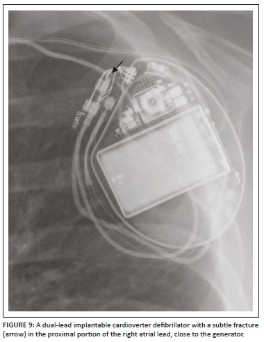
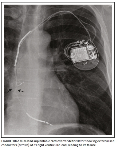
A detailed stepwise approach to the assessment of an ICD including its associated complications (Figures 8a and b, 9 and 10) on a CXR is like a pacemaker and is elaborated on in Table 1.
Cardiac resynchronisation therapy devices (implantable cardioverter defibrillator and pacemaker combinations)
ICD and pacemaker leads can be used in various combinations to produce a CRT device. The most common combination is a biventricular pacemaker with an ICD (Figure 11a and b), where the two pacemaker leads are noted in the right atrium and LV, while the shock lead of the ICD is in the RV. Cardiac resynchronisation therapy devices are mainly used for treating congestive heart failure (CHF). The CRT device can be more commonly an ICD (CRT-D) or a standalone pacemaker (CRT-P). The main aim of this device, in addition to a being pacemaker or ICD, is to synchronise the left ventricular contraction to improve the symptoms of CHF.5,10,12 The assessment of a CRT device on a CXR is no different from the other CIEDs.
By closely evaluating the CIED generator, a radiologist can determine if the device is MR conditional, as there are several 'absolute' contraindications to performing magnetic resonance imaging (MRI) in patients implanted with non-MR conditional CIEDs (elaborately detailed in Table 1),13 although some of these contraindications remain slightly disputed.14
Insertable cardiac monitor or implantable loop recorder
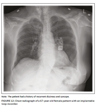
An insertable cardiac monitor (ICM) or ILR (Figure 12) is a miniaturised subcutaneous electrocardiographic monitoring device that has been extensively used for evaluating patients with unexplained syncope, symptomatic palpitations in adults, transient or occult atrial fibrillation (AF) and in the evaluation of a stroke.12 When compared to pacemakers and ICDs, ICMs do not require central venous access or direct contact with the endocardium, thereby negating the risk for endocardial infection. The device is generally implanted in the subcutaneous tissue overlying the left pectoralis muscle with a 1 cm - 2 cm incision that does not require conscious sedation. On a CXR, the ICM appears like a USB drive with no wires or leads attached to it. Insertable cardiac monitor mimics on a PA CXR include a USB flash drive, an e-vape device and a leadless cardiac pacemaker in the RV, which can be differentiated from them on a lateral CXR.1,15
Cardiac valves and valve replacements or repair
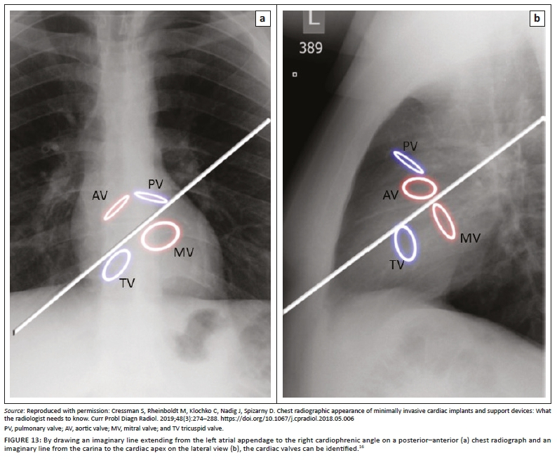
Landmarks of the cardiac silhouette and of the thorax can enable the identification of heart valves on a CXR. By drawing an imaginary line extending from the left atrial appendage to the right cardiophrenic angle (Figure 13)16 on a PA CXR and a line extending from the carina to the apex on the lateral view, positions of the valves can be roughly estimated. The pulmonic valve is the most superiorly positioned valve in both views, appearing in partial profile on both projections. On both views, the aortic valve is located superior to the axis line, appearing in profile and in front on the frontal and lateral views, respectively. In contrast, the mitral valve is located inferior to the axis lines on both views, appearing en face on the frontal projection and in profile on the lateral view. The tricuspid valve is located the most inferiorly on both projections, appearing anteriorly and en face on the lateral view. Nevertheless, because of anatomical and physiological variations and differences in radiographic projections, valve identification based solely on CXR can be unreliable, necessitating the need for additional details such as clinical history.16
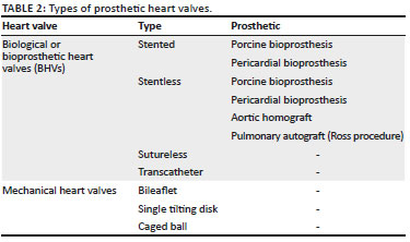
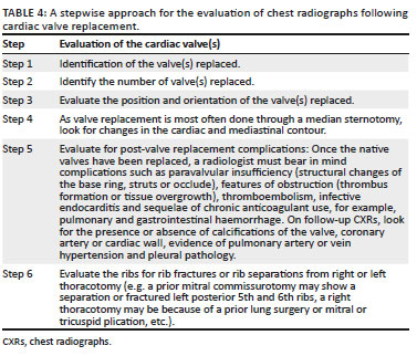
Valvular heart disease is associated with significant morbidity and mortality and affects roughly more than 100 million people worldwide, and the current standard of management is surgical valve replacement (Figures 14-20). Alternatively, transcatheter valve replacement without surgery has been gaining popularity over the last decade, especially in patients not suitable for surgery. Based on the leaflet material, the two types of prosthetic heart valves available are the mechanical and biological or bioprosthetic heart valves (BHVs).17 The various types of biological and mechanical prosthetic valves have been highlighted in Table 2, and they all look slightly different on imaging. The choice between mechanical valve and bioprosthetic valve remains controversial and is based on multiple parameters (Tables 2 and 3).18,19

Identification of the prosthetic heart valve on a CXR is made possible by detecting any or all its radiopaque parts which may include the base ring, stent, struts, cage, ball or disc. In some cases, a prosthesis may have no radiopaque component and hence cannot be identified radiographically. In most cases, the base ring is radiopaque. Several prosthetic valves have radiopaque struts or stents above or below the base ring. If the projections are long, the prosthetic heart valve is either a ball-in-cage or bioprosthesis. Literature sources are available,20 providing detailed algorithms guiding in the identification of prosthetic heart valves on CXRs which is beyond the scope of this article.
A stepwise approach to the evaluation of CXRs following cardiac valve replacement is elaborated in Table 4.21
Amplatzer septal occluder and Amplatzer ductal occluder
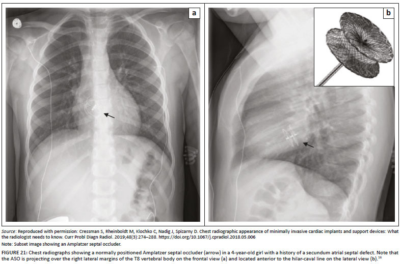
The Amplatzer septal occluder (ASO) (AVP, AGA Medical Corp., Golden Valley, MN, USA) is the most commonly used device for transcatheter closure of secundum atrial septal defects. The location of the ASO on a CXR is based on the position of the secundum atrial septal defect (ASD). On frontal CXRs (Figure 21a), the ASO is projected to the right or over the spinous processes between the T7 and T9 vertebral bodies, and on lateral CXRs (Figure 21b), the ASO is projected anterior to or over the hilar-caval line.22 ASO migration or embolisation is a recognised complication with an incidence of 0.4% - 1.1%, which can be identified on a CXR. Common sites of migration are the right cardiac chambers and pulmonary artery, while left-sided migration is rare.23
The Amplatzer ductal occluder (ADO) is a mushroom-shaped self-expandable nitinol wire mesh used for occluding large patent ductus arteriosus (PDA), while smaller PDAs are occluded by the transcatheter method using Gianturco coils. A recognised complication with the ADO, like the ASO, is device embolisation or migration (Figure 22a and b).24
Ethical consideration
All ethical considerations have been taken into account. No patient identity or patient information has been revealed.
Conclusion
As more and more patients are living with CIEDs and prosthetic valves, it is important that residents, radiologists and physicians are aware of these devices and recognise them on a CXR. Radiologists in particular have a specific and important role in the evaluation of these devices. An early and accurate identification of device malfunction, fracture or migration can help prompt the physician or surgeon to intervene in a timely manner and help avoid preventable life-threatening catastrophes.
Acknowledgements
Competing interests
The authors declare that they have no financial or personal relationships that may have inappropriately influenced them in writing this article.
Author's contributions
R.P.M. was the project leader and wrote the manuscript. T.A. was the lead subject authority, contributed to the supervision of the manuscript and helped acquire the images. V.P. contributed to the supervision of the manuscript and helped acquire the images. G.L. contributed to the supervision of the manuscript and helped acquire the images.
Funding
This research received no specific grant from any funding agency in the public, commercial or not-for-profit sectors.
Data availability statement
Data sharing is not applicable to this article as no new data were created or analysed in this study.
Disclaimer
The views and opinions expressed in this article are those of the authors and do not necessarily reflect the official policy or position of any affiliated agency of the authors.
References
1. Brixey AG, Fuss C. Innovative cardiac devices on chest imaging: An update. J Thorac Imaging. 2017 Nov;32(6):343-357. https://doi.org/10.1097/RTI.0000000000000304 [ Links ]
2. Tom J. Management of patients with cardiovascular implantable electronic devices in dental, oral, and maxillofacial surgery. Anesth Prog. 2016 Summer;63(2):95-104. https://doi.org/10.2344/0003-3006-63.2.95 [ Links ]
3. Buch E, Boyle NG, Belott PH. Pacemaker and defibrillator lead extraction. Circulation. 2011;123:e378-e380. https://doi.org/10.1161/CIRCULATIONAHA.110.987354 [ Links ]
4. Kotsakou M, Kioumis I, Lazaridis G, et al. Pacemaker insertion. Ann Trans Med. 2015;3(3):42. [ Links ]
5. Aguilera AL, Volokhina YV, Fisher KL. Radiography of cardiac conduction devices: A comprehensive review. Radiographics. 2011 Oct;31(6):1669-1682. https://doi.org/10.1148/rg.316115529 [ Links ]
6. Rajappan K. Permanent pacemaker implantation technique: Part II. Heart. 2009 Feb;95(4):334-342. https://doi.org/10.1136/hrt.2008.156372 [ Links ]
7. Kossaify A. Temporary endocavitary pacemakers and their use and misuse: The least is better. Clin Med Insights Cardiol. 2014;8:9-11. https://doi.org/10.4137/CMC.S13272 [ Links ]
8. Godoy MC, Leitman BS, De Groot PM, Vlahos I, Naidich DP. Chest radiography in the ICU: Part 2, Evaluation of cardiovascular lines and other devices. AJR Am J Roentgenol. 2012 Mar;198(3):572-581. https://doi.org/10.2214/AJR.11.8124 [ Links ]
9. Sklyar E, Bella JN. Evaluation and monitoring of patients with cardiovascular implantable electronic devices undergoing noncardiac surgery. Health Serv Insights. 2017 Mar 20;10:1178632916686073. https://doi.org/10.1177/1178632916686073 [ Links ]
10. Alandete Germán SP, Isarria Vidal S, Domingo Montañana ML, De la Vía Oraá E, Vilar Samper J. Pacemakers and implantable cardioverter defibrillators, unknown to chest radiography: Review, complications and systematic reading. Eur J Radiol. 2015 Mar;84(3):499-508. https://doi.org/10.1016/j.ejrad.2014.12.011 [ Links ]
11. Conyers JM, Rajiah P, Ahn R, Abbara S, Saboo SS. Imaging features of leadless cardiovascular devices. Diagn Interv Radiol. 2018;24(4):203-208. https://doi.org/10.5152/dir.2018.17462 [ Links ]
12. Silveira I, Sousa MJ, Antunes N, et al. Efficacy and safety of implantable loop recorder: Experience of a center. J Atr Fibrillation. 2016 Aug 31;9(2):1425. [ Links ]
13. Korutz AW, Obajuluwa A, Lester MS, et al. Pacemakers in MRI for the neuroradiologist. AJNR Am J Neuroradiol. 2017 Dec;38(12):2222-2230. https://doi.org/10.3174/ajnr.A5314 [ Links ]
14. Muthalaly RG, Nerlekar N, Ge Y, Kwong RY, Nasis A. MRI in patients with cardiac implantable electronic devices. Radiology. 2018 Nov;289(2):281-292. https://doi.org/10.1148/radiol.2018180285 [ Links ]
15. Pachulski R, Cockrell J, Solomon H, Yang F, Rogers J. Implant evaluation of an insertable cardiac monitor outside the electrophysiology lab setting. PLoS One. 2013;8(8):e71544. https://doi.org/10.1371/journal.pone.0071544 [ Links ]
16. Cressman S, Rheinboldt M, Klochko C, Nadig J, Spizarny D. Chest radiographic appearance of minimally invasive cardiac implants and support devices: What the radiologist needs to know. Curr Probl Diagn Radiol. 2019;48(3):274-288. https://doi.org/10.1067/j.cpradiol.2018.05.006 [ Links ]
17. Dangas GD, Weitz JI, Giustino G, Makkar R, Mehran R. Prosthetic heart valve thrombosis. J Am Coll Cardiol. 2016 Dec 20;68(24):2670-2689. https://doi.org/10.1016/j.jacc.2016.09.958 [ Links ]
18. Altaani HA, Jaber S. Tricuspid valve replacement, mechanical vs. biological valve, which is better? Int Cardiovasc Res J. 2013;7(2):71-74. [ Links ]
19. Tillquist MN, Maddox TM. Cardiac crossroads: Deciding between mechanical or bioprosthetic heart valve replacement. Patient Prefer Adherence. 2011;5:91-99. https://doi.org/10.2147/PPA.S16420 [ Links ]
20. Mehlman DJ. A pictorial and radiographic guide for identification of prosthetic heart valve devices. Prog Cardiovasc Dis. 1988 May-Jun;30(6):441-464. https://doi.org/10.1016/0033-0620(88)90006-0 [ Links ]
21. Steiner RM, Mintz G, Morse D, Kotler M, Flicker S, Raichlen JS. The radiology of cardiac valve prostheses. Radiographics. 1988 Mar;8(2):277-298. https://doi.org/10.1148/radiographics.8.2.3283868 [ Links ]
22. Lee EY, Siegel MJ, Chu CM, Gutierrrez FR, Kort HW. Amplatzer atrial septal defect occlude for pediatric patients: Radiographic appearance. Radiology. 2004;233(2):471-476. https://doi.org/10.1148/radiol.2332031707 [ Links ]
23. Martinez-Quintana E, Rodriguez-Gonzalez F. Risks factors for atrial septal defect occlusion device migration. Int J Angiol. 2016;25(5):e63-e65. https://doi.org/10.1055/s-0034-1395976 [ Links ]
24. Haponiuk I, Chojnicki M, Jaworski R, et al. Miniinvasive hybrid procedure for device migration after percutaneous closure of persistent arterial duct: A case report. Wideochir Inne Tech Maloinwazyjne. 2012;7(3):202-205. https://doi.org/10.5114/wiitm.2011.27367 [ Links ]
 Correspondence:
Rishi Mathew
dr_rishimathew@yahoo.com
Received: 04 Mar. 2019
Accepted: 05 May 2019
Published: 31 July 2019

