


Services on Demand
Article
 English (pdf)
 Article in xml format
 Article references
Indicators

Related links
-
 Cited by Google
 -
 Similars in Google
Share

 Permalink
SA Journal of Radiology
On-line version ISSN 2078-6778
Print version ISSN 1027-202X
S. Afr. J. radiol. (Online) vol.20 n.2 Johannesburg 2016
http://dx.doi.org/10.4102/sajr.v20i2.1046
REVIEW ARTICLE
Imaging of patients with implanted devices and arrhythmia
Nam Ju LeeI; Harold I. LittII
IDepartment of Radiology and Radiological Science, Johns Hopkins University, United States
IIDepartment of Radiology, University of Pennsylvania, United States
ABSTRACT
Expanding implantable cardioverter-defibrillator (ICD) indications and significant morbidity and mortality reduction benefits have resulted in a large number of routine ICD implants with appropriate ICD shocks for ventricular arrhythmias. The side-effects and lack of long-term efficacy of antiarrhythmics have made ventricular tachycardia (VT) ablation an increasingly attractive treatment option. Although cardiac magnetic resonance imaging (CMR) is considered the gold standard technique for imaging of myocardial fibrosis to diagnose and guide VT ablation targets in patients with cardiac arrhythmia, safety concerns and significant artifacts from the devices significantly limit the application of CMR. We discuss how to decrease artifact from cardiac devices and the role of a modified inversion pulse late gadolinium enhancement (LGE) CMR sequence as a useful tool in this setting, and we review techniques, safety protocols and limitations from the perspective of our institution's experience.
Introduction
In the United States, approximately 116 000 implantable cardioverter-defibrillators (ICDs) and 397 000 cardiac pacemakers were implanted in 2009.1,2 Expanding ICD indications and significant morbidity and mortality reduction benefits have resulted in a large number of routine ICD implants with appropriate ICD shocks for ventricular arrhythmias.3 The side-effects and lack of long-term efficacy of antiarrhythmics have made ventricular tachycardia (VT) ablation an increasingly attractive treatment option.4 In 70% to 90% of patients with a secondary prevention ICD, a substrate-guided VT ablation must be pursued because of haemodynamic instability or multiple VT morphologies.4 Late gadolinium enhancement (LGE) magnetic resonance imaging (MRI) is an important technique for assessing myocardial viability and fibrosis. For patients undergoing catheter ablation of VT, the assessment of scar transmurality, size and location provided by LGE MRI enables accurate identification of the arrhythmogenic substrate, leading to more effective selection of sites for ablation.1,5 This approach has the potential to decrease procedure times and increase success rates for ablation procedures.1 Up to 75% of patients who could benefit from LGE MRI have implanted cardiac devices6 and will have an indication for one or more cardiac MRI examinations during their lifetime. The presence of these devices presents two issues for cardiac MRI: safety and image artifacts.1
Traditionally, cardiac devices have been a contraindication to MRI owing to safety concerns with a potential risk to pacemaker-dependent and ICD patients, of temporary or permanent device malfunction, mechanical forces causing dislocation and movement of the device or leads, and induction of arrhythmia.6 Radiofrequency (RF) energy absorbed by leads may lead to heating, which could result in oedema or scarring at the lead tip-myocardial interface or an increase in pacing thresholds that may need to be addressed by increasing device output. An ICD may interpret gradients as VT or ventricular fibrillation2,3,4,7 and pacemakers may induce arrhythmia by interpreting RF pulses or gradients as beats and provide a paced beat at the same time as a natural beat.
Pacemakers have many additional features, most of which should be turned off for MRI. There is also a manufacturer-dependent 'magnet rate', which may be controlled by a reed switch. The reed switch is activated by a magnet, which brings two metal strips together to complete an electrical circuit. In a MRI system, the reed switch will flip about 50% of the time and generally will change pacing to an asynchronous mode at the magnet rate, which varies from 60 to 100 bpm depending upon the manufacturer.3,4,7 The safety aspects of MRI in device patients has been studied extensively in the past decade, demonstrating that cardiac MRI can be performed safely at 1.5 Tesla (T) in patients with implanted cardiac devices, provided that their rhythm is not device dependent and appropriate guidelines are followed.1 At the Hospital of the University of Pennsylvania, we perform MRI on patients with non-MRI-conditional pacemakers and ICDs routinely using the protocol described below. More recently, an MR-conditional ICD/cardiac resynchronisation therapy system has been approved3,6 and shown to be safe and effective when scanned at 1.5T.8
The soft-tissue contrast available with MR techniques is advantageous in diagnosing complications near an increasing variety of MR-safe metallic hardware, although the spatial encoding mechanisms utilised in conventional MRI methods are often severely compromised. Mitigating these encoding difficulties has been the focus of numerous research investigations over the past two decades. Such approaches include view-angle tilting, short echo time projection reconstruction acquisitions, single-point imaging, prepolarised MRI, and postprocessing image correction.9
Multispectral MRI techniques, such as multi-acquisition variable-resonance image combination (MAVRIC), where the off-resonance induced by metallic implants is countered by imaging at multiple resonance frequencies9,10 and combining the resultant images to produce a composite artifact-free image, is a promising method for 3D imaging. Another technique, that of slice encoding for metal artifact correction (SEMAC),11,12 where the metal-induced off-resonance is countered by a combination of view-angle tilting (VAT)13,14 and phase encoding in the z-direction, together with an appropriate reconstruction scheme, has been successfully applied in musculoskeletal imaging applications. A hybrid approach that combines MAVRIC and SEMAC has also been proposed.15
Cardiac MRI in patients with arrhythmia and cardiac devices
All cardiac magnetic resonance imaging (CMR) sequences are affected by the metallic device generator, which induces strong off-resonance field perturbations within the myocardium. A right-sided generator, or generator away from the heart, may reduce inhomogeneity in the region of the heart. In comparison with pacemakers, the larger size of the ICD pulse generator and large coil affect image quality substantially. Sequences less affected by field inhomogeneity may be used, for example, spin echo instead of gradient echo for localisers, non-balanced gradient echo cine images instead of balanced gradient echo (Figure 1), or by reducing echo time (TE) and increasing bandwidth (Figure 2) as much as possible.16 Steady-state free-precession (SSFP) gradient echo (Figure 2c) and inversion recovery (IR) sequences with longer TEs are associated with increased magnetic susceptibility artifacts compared with non-balanced gradient echo and spin echo sequences. Artifacts resulting from pacemaker/ICD generators can be reduced by use of lower magnetic field strength and shorter TEs; however, such adjustments may compromise the image signal intensity and contrast. The use of spin echo techniques produces black blood contrast, which is not always desirable and is typically associated with a high specific absorption rate (SAR), which may reduce safety.17,18 Recently, Schwitter et al. reported that fast gradient echo (FGE) produces better quality and smaller ICD-related artifacts for CMR than SSFP in patients with an MRI-conditional ICD system. FGE yielded good to moderate image quality in this multicentre study in 74% of left ventricle (LV) and 84% of right ventricle (RV) acquisitions. In these patients implanted with ICD systems designed for the MR environment, CMR can offer diagnostic information in most cases.16 The SSFP sequence is the most commonly used sequence for cardiac functional analysis, but is more susceptible to field inhomogeneities than FGE. Importantly, many pulse sequences used in clinical MRI practice for viability/scar imaging, myocardial perfusion imaging, tagging and flow measurements, use FGE-type readouts. Also, highly accelerated cardiac acquisitions based on novel compressed sensing strategies can use an FGE read-out, and are therefore expected to work reliably in patients with this implanted ICD system and avoid SSFP-related artifacts.16
The use of an inversion pulse to properly null the myocardium on LGE sequences requires field homogeneity, making artifacts from implanted devices particularly problematic for these sequences (Figure 3).18 Spurious myocardial hyperintensity results from insufficient spin inversion, which in turn results from inadequate spectral bandwidth of the nonselective adiabatic IR pulses.1 On LGE sequences with a standard inversion pulse, cardiac devices generate central dark signal in the direct vicinity of the ICD generator (frequently 3 cm - 5 cm surrounding the ICD), where the metal components result in a frequency shift that is sufficiently strong to introduce an intravoxel dephasing in the MRI signal, and a surrounding ring-like hyperintensity artifact that is created by a metal-induced frequency shift not strong enough to cause a signal void but sufficiently strong to cause an improper inversion of the signal, which appears similar to the hyperenhancement of myocardial fibrosis.2 The artifact affects > 50% of the LV, predominantly the anterior and apical segments owing to the proximity of these areas of the myocardium to the ICD generator.3 These hyperintensity artifacts can mask regions of scar tissue or other late enhancement, severely compromising the diagnostic value of LGE MRI, leading to false negative or false positive diagnoses.1 Given the increasing importance of fibrosis imaging in the diagnosis, follow-up and treatment of VT patients and other cardiac diseases (e.g. arrhythmogenic right ventricular cardiomyopathy or sarcoidosis), there is a need for strategies to address the challenge posed by ICD artifacts in LGE CMR.
Whilst improved designs of ICD and leads will minimise artifacts and improve safety in the longer term, short-term solutions for artifact reduction are most likely to result from new CMR protocols using techniques such as bandwidth modulation.2 These multi-kHz off-resonance effects resulting in hyperintensity artifacts can be considerably reduced by using a wideband IR pulse in the LGE sequence without requiring additional hardware, time or reconstruction.2,7This technique has recently been extended to a modified wideband 3-D LGE sequence,1 and to allow cardiac T1 mapping without significant ICD-induced artifacts.19 MRI is emerging as a reliable noninvasive test for myocardial tissue characterisation using cardiac T1 mapping and extracellular volume (ECV) fraction determination. Unlike myocardial biopsy, these MRI methods provide a means to sample the whole heart noninvasively.19,20 In the context of heart failure (HF) induced by nonischaemic cardiomyopathy, cardiac T1 and ECV fraction mapping may be better than LGE MRI for quantification of myocardial fibrosis burden. An arrhythmia-insensitive-rapid (AIR) cardiac T1 mapping pulse sequence21 with a short scan time (i.e. 2-3 heart beats) is well suited for imaging patients with advanced HF, because they often have rapid heart rates and/or irregular heart rhythm and/or limited breath-hold capacity. Hong et al. incorporated a saturation RF pulse with wide frequency bandwidth to achieve uniform T1 weighting in the heart in the presence of an ICD. In their study, T1 measured in the presence of an ICD using the original AIR sequence was significantly lower (absolute percentage error > 10.1%) than the control T1 values measured with original AIR without ICD, whereas T1 measured with wideband AIR with ICD was similar (absolute percentage error < 2.0%).19
How we scan patients with implanted devices
Patient screening
When a physician requests CMR in a patient with a device, the case is evaluated by an attending radiologist, who determines both whether another acceptable diagnostic modality is available, and also if the information gained from the MRI will have considerable impact on patient treatment or prognosis. After this screening, we gather information regarding the device, including year of manufacture and model, date of placement, presence of epicardial leads/coil system or abandoned/capped endovascular leads, pacemaker dependence and renal function. The presence of an older device (entered the market before 2000), leads or generator in place for less than 6 weeks, presence of epicardial, abandoned or capped leads, pacemaker dependence in the presence of an ICD, and glomerular filtration rate (GFR) < 30 mL/min. are considered factors that engender additional risk and may prompt additional safety review or a modified consent process.
Safety protocol and pre- and post-MRI ICD interrogation
Multidisciplinary collaboration and strategic planning are important for establishing a successful program for MRI in device patients. In our institution, a group including cardiovascular radiologists and electrophysiology (EP) physicians developed a comprehensive clinical protocol addressing patient care and flow during and after the CMR. Informed consent is obtained from all patients after a discussion of the risks and benefits of the procedure. The devices are interrogated and reprogrammed by an electophysiologist (or EP physician's assistant) as appropriate before and after MRI according to the guidelines of the European Society of Cardiology22 and the literature.4,23 Tachyarrhythmia detection and therapy is disabled in patients with an ICD. In patients dependent on pacemakers, bradycardia parameters are programmed to an asynchronous mode at an appropriate support rate. In non-dependent patients, the rate-responsiveness feature is temporarily disabled, and demand pacing modes left in place. Additional pacemaker features are generally turned off to limit interference. ECG, blood pressure and pulse oximetry is continuously monitored during MRI by an advanced cardiovascular life support (ACLS)-certified provider and clinical symptoms are recorded. A device programmer is kept on hand and an EP provider is either present throughout the exam or readily available. After completion of the scan, the device is re-interrogated to assess any parameter changes, and programming is restored to the initial pre-procedure mode.
Cardiac magnetic resonance protocol
CMR is performed using a 1.5T scanner (Siemens Avanto, Espree, or Aera, Malvern, PA, USA). Whilst CMR in device patients has been reported at 3T,24 we have chosen to restrict studies to 1.5T. All imaging sequences are adjusted to obtain SAR < 2.0 W/kg. Our CMR protocol in patients with cardiac devices includes: localisers performed using spin echo technique, axial single-shot dark blood half Fourier turbo spin echo, multiplanar long-axis non-balanced gradient echo cine, an optional perfusion sequence, post-contrast short-axis non-balanced gradient echo cine, a TI scout, and both standard and wideband inversion pulse LGE sequences using a phase-sensitive IR technique. Gradient echo cine sequences are obtained with minimum TE and a 6 mm slice thickness. The optimal inversion time to achieve 'nulling' of the normally enhancing myocardium is estimated using a cine inversion scout sequence before obtaining delayed enhancement sequence; this is the only balanced gradient echo (SSFP) sequence in the acquisition, and is usually subject to considerable artifact. We obtain short-axis cine images after contrast both for time efficiency and as an additional method to evaluate myocardial enhancement if LGE sequences are severely affected by artifact. As the wideband LGE sequence is not currently available for clinical use by the manufacturer of our scanner, its use at our institution is under a research protocol, and therefore both conventional and wideband LGE sequences are acquired.
Modified inversion pulse sequence
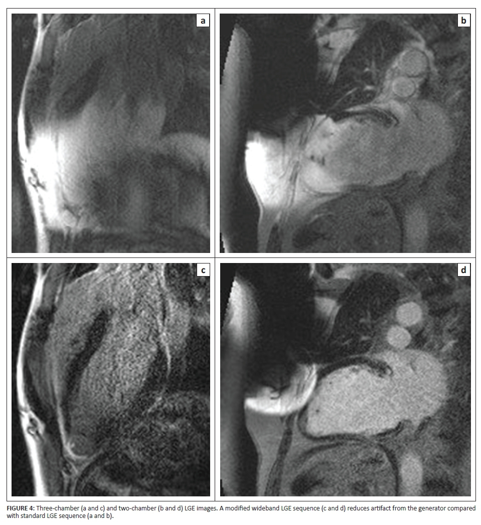
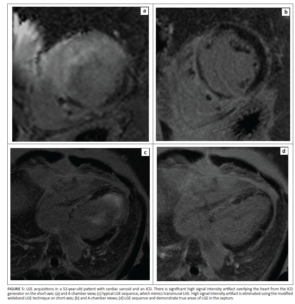
The RF inversion pulse in the conventional LGE sequence on our 1.5T units is a hyperbolic secant adiabatic inversion pulse. Although the inversion pulse is spatially nonselective, it has a spectral bandwidth of 1.1 kHz. For a cardiac device generator that is typically 5 cm - 10 cm away from the patient's heart, the expected resonance offset of the myocardium is in the 2 kHz - 6 kHz range, well outside the bandwidth of the inversion pulse currently used. Consequently, the signal from the affected myocardium is not properly inverted and is typically hyperintense, undermining appropriate diagnostic interpretation (Figure 3). A wideband adiabatic inversion pulse (bandwidth 3.8 kHz) properly inverts the signal from the myocardium affected by the device generator (Figures 4 and 5). This inversion pulse was implemented into the existing two-dimensional IR LGE sequence, replacing the conventional inversion pulse.
As the modified sequence requires higher B1 amplitude resulting in high SAR, we performed all studies on a 1.5T magnet.2 In an analysis of 264 CMR studies performed using the modified inversion pulse sequence, 20 out of 264 cases (7.5%) were deemed suboptimal, with ICD artifact limiting diagnosis. Sixteen out of the 264 cases were severely limited and two cases were felt to be mildly limited. No complications have been seen specifically related to the use of the wideband sequence.
Several factors influence the size of the metallic artifact including metallic composition such as stainless steel and larger size of the device (ICDs are generally larger than pacemakers), the orientation of the ICD with respect to the direction of the magnetic field, the type of pulse sequence applied such as SSFP gradient echo, IR sequences with longer TEs, and sequence parameters (such as magnetic field strength, voxel size, and echo train length).17,18 Non-ferromagnetic components such as titanium and pulse sequences such as spin echo sequences result in less susceptibility artifact. ICD leads contain little ferromagnetic components compared to the generator, resulting in minimal artifact. Lower magnetic field strength, shorter TEs, and a smaller field of view (FOV) can decrease artifact size although image quality may be compromised.17,18 BMI and device-heart distance correlate with the size of ICD artifacts.3The most direct effect of scanning larger patients is the need for a larger FOV, which involves lower gradient strengths compared with imaging at a smaller FOV. This results in decreased RF depth penetration, decreased spatial resolution, and decreased signal-to-noise ratio, all of which lead to decreased image resolution and potentially a larger artifact size,25 although this effect may be offset by a greater distance from the generator to the heart border. Additional chemical shift artifact may play a role in the setting of increased fat-water interfaces within the subcutaneous fat.
Conclusion
Artifacts related to implanted devices are mostly related to field inhomogeneity and can be reduced by increasing the distance from the heart, decreasing dependence on field homogeneity using short TE non-balanced gradient echo (GRE) cine and wideband LGE sequences. Our experience with performing cardiac MRI in patients with implanted devices over 10 years has shown that the modified LGE sequence removes most device artifact and is useful to evaluate myocardial fibrosis and scar for both diagnostic purposes and to identify arrhythmogenic substrate prior to planned ablation. However, acquisition of pre-ICD implantation CMR will provide detailed scar characterisation not affected by metal artifact and should be considered in patients thought to be likely to require future VT ablation.
Competing interests
The authors declare that they have no financial or personal relationships which may have inappropriately influenced them in writing this article.
Authors' contributions
N.J.L. collected and analysed all data at the Perelman School of Medicine of the University of Pennsylvania, prepared the initial manuscript draft whilst working at Staten Island University Hospital, and edited the manuscript whilst working at Johns Hopkins University. H.L. was the project leader, was responsible for the project design, supervised all data acquisition and analysis, and edited and finalised the manuscript at the Perelman School of Medicine of the University of Pennsylvania.
References
1. Rashid S, Rapacchi S, Shivkumar K, Plotnik A, Finn JP, Hu P. Modified wideband three-dimensional late gadolinium enhancement MRI for patients with implantable cardiac devices. Magn Reson Med. 2016;75(2):572-584. http://dx.doi.org/10.1002/mrm.25601 [ Links ]
2. Rashid S, Rapacchi S, Vaseghi M, Tung R, Shivkumar K, Finn JP, et al. Improved late gadolinium enhancement MR imaging for patients with implanted cardiac devices. Radiology. 2014;270(1):269-74. http://dx.doi.org/10.1148/radiol.13130942 [ Links ]
3. Mesubi O, Ahmad G, Jeudy J, et al. Impact of ICD artifact burden on late gadolinium enhancement cardiac MR imaging in patients undergoing ventricular tachycardia ablation. Pacing Clin Electrophysiol. 2014;37(10):1274-1283. http://dx.doi.org/10.1111/pace.12405 [ Links ]
4. Dickfeld T, Tian J, Ahmad G, et al. MRI-guided ventricular tachycardia ablation: Integration of late gadolinium-enhanced 3D scar in patients with implantable cardioverter-defibrillators. Circ Arrhythm Electrophysiol. 2011;4(2):172-184. http://dx.doi.org/10.1161/CIRCEP.110.958744 [ Links ]
5. Tian J, Ahmad G, Mesubi O, Jeudy J, Dickfeld T. Three-dimensional delayed-enhanced cardiac MRI reconstructions to guide ventricular tachycardia ablations and assess ablation lesions. Circ Arrhythm Electrophysiol. 2012;5(2):e31-e35. http://dx.doi.org/10.1161/CIRCEP.111.968636 [ Links ]
6. Nazarian S, Beinart R, Halperin HR. Magnetic resonance imaging and implantable devices. Circ Arrhythm Electrophysiol. 2013;6(2):419-428. http://dx.doi.org/10.1161/CIRCEP.113.000116 [ Links ]
7. Stevens SM, Tung R, Rashid S, et al. Device artifact reduction for magnetic resonance imaging of patients with implantable cardioverter-defibrillators and ventricular tachycardia: Late gadolinium enhancement correlation with electroanatomic mapping. Heart Rhythm. 2014;11(2):289-298. http://dx.doi.org/10.1016/j.hrthm.2013.10.032 [ Links ]
8. Gold MR, Sommer T, Schwitter J, et al. Full-body MRI in patients with an implantable cardioverter-defibrillator: Primary results of a randomized study. J Am Coll Cardiol. 2015;65(24):2581-2588. http://dx.doi.org/10.1016/j.jacc.2015.04.047 [ Links ]
9. Koch KM, Hargreaves BA, Pauly KB, Chen W, Gold GE, King KF. Magnetic resonance imaging near metal implants. J Magn Reson Imaging. 2010;32(4):773-787. http://dx.doi.org/10.1002/jmri.22313 [ Links ]
10. Koch KM, Lorbiecki JE, Hinks RS, King KF. A multispectral three-dimensional acquisition technique for imaging near metal implants. Magn Reson Med. 2009;61(2):381-390. http://dx.doi.org/10.1002/mrm.21856 [ Links ]
11. Lu W, Pauly KB, Gold GE, Pauly JM, Hargreaves BA. SEMAC: Slice encoding for metal artifact correction in MRI. Magn Reson Med. 2009;62(1):66-76. http://dx.doi.org/10.1002/mrm.21967 [ Links ]
12. Hargreaves BA, Chen W, Lu W, et al. Accelerated slice encoding for metal artifact correction. J Magn Reson Imaging. 2010;31(4):987-996. http://dx.doi.org/10.1002/jmri.22112 [ Links ]
13. Butts K, Pauly JM, Gold GE. Reduction of blurring in view angle tilting MRI. Magn Reson Med. 2005;53(2):418-424. http://dx.doi.org/10.1002/mrm.20375 [ Links ]
14. Cho ZH, Kim DJ, Kim YK. Total inhomogeneity correction including chemical shifts and susceptibility by view angle tilting. Med Phys. 1988;15(1):7-11. http://dx.doi.org/10.1118/1.596162 [ Links ]
15. Koch KM, Brau AC, Chen W, et al. Imaging near metal with a MAVRIC-SEMAC hybrid. Magn Reson Med. 2011;65(1):71-82. http://dx.doi.org/10.1002/mrm.22523 [ Links ]
16. Schwitter J, Gold MR, Al Fagih A, et al. Image quality of cardiac magnetic resonance imaging in patients with an implantable cardioverter defibrillator system designed for the magnetic resonance imaging environment. Circ Cardiovasc Imaging. 2016;9(5):e004025. [ Links ]
17. Stradiotti P, Curti A, Castellazzi G, Zerbi A. Metal-related artifacts in instrumented spine. Techniques for reducing artifacts in CT and MRI: State of the art. Eur Spine J. 2009;18(suppl. 1):102-8. http://dx.doi.org/10.1007/s00586-009-0998-5 [ Links ]
18. Sasaki T, Hansford R, Zviman MM, et al. Quantitative assessment of artifacts on cardiac magnetic resonance imaging of patients with pacemakers and implantable cardioverter-defibrillators. Circ Cardiovasc Imaging. 2011;4(6):662-670. http://dx.doi.org/10.1161/CIRCIMAGING.111.965764 [ Links ]
19. Hong K, Jeong EK, Wall TS, Drakos SG, Kim D. Wideband arrhythmia-insensitive-rapid (AIR) pulse sequence for cardiac T1 mapping without image artifacts induced by an implantable-cardioverter-defibrillator. Magn Reson Med. 2015;74(2):336-345. http://dx.doi.org/10.1002/mrm.25712 [ Links ]
20. Miller CA, Naish JH, Bishop P, et al. Comprehensive validation of cardiovascular magnetic resonance techniques for the assessment of myocardial extracellular volume. Circ Cardiovasc Imaging. 2013;6(3):373-383. http://dx.doi.org/10.1161/CIRCIMAGING.112.000192 [ Links ]
21. Fitts M, Breton E, Kholmovski EG, et al. Arrhythmia insensitive rapid cardiac T1 mapping pulse sequence. Magn Reson Med. 2013;70(5):1274-1282. http://dx.doi.org/10.1002/mrm.24586 [ Links ]
22. Roguin A, Schwitter J, Vahlhaus C, et al. Magnetic resonance imaging in individuals with cardiovascular implantable electronic devices. Europace. 2008;10(3):336-346. http://dx.doi.org/10.1093/europace/eun021 [ Links ]
23. Nazarian S, Halperin HR. How to perform magnetic resonance imaging on patients with implantable cardiac arrhythmia devices. Heart Rhythm. 2009;6(1):138-143. http://dx.doi.org/10.1016/j.hrthm.2008.10.021 [ Links ]
24. Ranjan R, McGann CJ, Jeong EK, et al. Wideband late gadolinium enhanced magnetic resonance imaging for imaging myocardial scar without image artefacts induced by implantable cardioverter-defibrillator: A feasibility study at 3 T. Europace. 2015;17(3):483-488. http://dx.doi.org/10.1093/europace/euu263 [ Links ]
25. Uppot RN, Sahani DV, Hahn PF, Gervais D, Mueller PR. Impact of obesity on medical imaging and image-guided intervention. AJR Am J Roentgenol. 2007;188(2):433-440. http://dx.doi.org/10.2214/AJR.06.0409 [ Links ]
 Correspondence:
Harold Litt
harold.litt@uphs.upenn.edu
Received: 06 June 2016
Accepted: 28 July 2016
Published: 11 Nov. 2016

