


Services on Demand
Article
 English (pdf)
 Article in xml format
 Article references
Indicators

Related links
-
 Cited by Google
 -
 Similars in Google
Share

 Permalink
SAIEE Africa Research Journal
On-line version ISSN 1991-1696
Print version ISSN 0038-2221
SAIEE ARJ vol.112 n.3 Observatory, Johannesburg Sep. 2021
On the Optimal Spine Morphology of Rapidly Accelerating Quadrupeds
Callen Fisher; Amir Patel
Faculty of Electrical Engineering, University of Cape Town, 7700 Rondebosch, South Africa fshcal001@myuct.ac.za. Member, IEEE
ABSTRACT
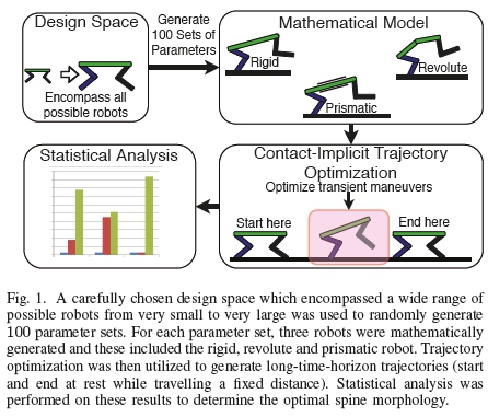
Animals exploit spine actuation during rapid locomotion, however this has only recently become a focal point in robotics. Roboticists have used a multitude of spine configurations in their platforms but the optimal design for rapid acceleration and deceleration maneuvers is yet to be discovered. In this paper, we endeavour to find this optimal spine morphology by using large-scale Monte Carlo trajectory optimization simulations on long-time-horizon minimum time problems (start and end at rest while travelling a fixed distance of 30 spine lengths). Broad applicability of the results was ensured by generating 100 sets of robot parameters at random from a carefully selected design space, comparing the performance of the rigid, revolute and prismatic spine morphology. Using bootstrapping techniques, it was determined with a 78.8% probability that the prismatic spine morphology was the optimal spine for these long-time-horizon trajectories. These results will serve as a guide for designers of future, agile quadruped robots.
Keywords: legged robot, trajectory optimization, optimal control
I. INTRODUCTION
In nature, maneuverability is paramount to survival, as seen during high-speed pursuits when hunting and evading predators [1]. During these pursuits, animals such as the cheetah (Acinonyx jubatus) [2], [3] and greyhound (Canis familiaris) [4], [5] can be seen to perform high-speed, agile transient maneuvers such as rapid turning, accelerating and stopping. Studying these motions, one cannot help but observe the motion of the spine and how it is fundamental to these motions [2]. This is verified by studies done on cheetahs which revealed that the spine effectively increases the stride length by 5% which results in an increase in the top speed by 10% [6], [7].
However looking at the robotics literature, maneuvers such as rapid acceleration and deceleration have not been a focal point. This is partly due to the complexity involved in studying and modelling these motions. Previous research on biped and quadruped robots has shown that the optimal method of accelerating and deceleration is to launch straight into the desired gait/velocity instead of performing multiple gait transitions [8]. These robots contained rigid spines, unlike what is observed in nature.
Flexible spines are frequently found in nature in many different shapes, sizes and degrees of flexibility varying across a large number of species. These spines often consist of a multitude of actuated rigid links. Despite being common place and crucial in nature, the spine (active [9]-[16] or passive [17]-[21]) is not commonly found in robotics. To date there has been little focus on transient maneuvers in robotics and the main focus has been on steady-state locomotion and energy efficiency [11], [22] often utilizing the spines as a passive actuator (a spring system [18], [20]) as opposed to an active spine [10], [12]-[16]. This may be one of the reasons as to why the current robotic platforms are not as agile as animals.
For robotics, the fundamental question we are trying to answer is: When designing a legged robot to perform transient motions (rapid acceleration and deceleration), what spine morphology should be utilized? Reviewing the literature there are a number of robotic spines utilized by quadruped robots, with the three most popular spines being the rigid [22], [23], revolute [13], [18], [19], [21] and prismatic [20], [24] spine. These studies have all been focused on steady-state locomotion and not rapid transient locomotion.
Flexible spines in robotics (often consisting of a large number of rigid links connected through rotary joints [12], [17] or consisting of a leaf spring [9], [25] or tensegrity spine [26], [27]) are infeasible for rapid transient maneuvers due to their complexity in modelling and control as well as requiring a large number of actuators. There are thus two ways to realize a flexible spine for agile robots. The first is to reduce the number of degrees of freedom of the spine to 1 resulting in the revolute spine. This spine will still encompass the bending nature of the flexible spine while only requiring one actuator. The second way is to look at the resultant effect the spine produces. It has been shown to increase the stride length in cheetah's [6], [7] which can be achieved using a prismatic actuator, as a robot does not have internal organs which would limit its movement. However, which one is the optimal spine morphology for rapid acceleration and deceleration maneuvers?
This study aims at providing general insight into the optimal spine morphology for rapid acceleration (and deceleration) maneuvers. The work presented here is an extension to our previous effort [28], which focused purely on rapid acceleration with a prescribed gait pattern. This research has been expanded by analyzing a full trajectory (containing an acceleration, steady-state and deceleration phase) while allowing the optimizer to choose the gait pattern (using contact-implicit optimization methods) and allows the feet to slip (a friction cone was enforced). This research is limited to the planar case and follows a similar methodology to [29]. Due to the complexity of these simulations, and the computational requirements (2 months to complete the simulations on 12 identical computers), only acceleration and deceleration maneuvers of planar quadrupeds (100 randomly generated robots) with a rigid, revolute and prismatic spine were analyzed and compared, summarized in Fig. 1.
This paper begins by describing the methodology followed throughout the research in Section II, which includes details on the trajectory optimization method. The results and discussion are presented in Section III and IV. The paper ends with the conclusions and future work in Section V.
II. Methodology
As general insights into the optimal spine morphology for acceleration and deceleration were the aim of this research, a large number of robots needed to be investigated and compared. Due to the infinite number of possible robot parameter sets, it is intractable to analyze all, or even to perform a course grid search over the parameter space. Instead, large-scale Monte Carlo simulations were run on a small subset of these parameters. Statistical methods in the form of bootstrapping [30] were used to gain general insight into which spine morphology is the optimal morphology for these long-time-horizon trajectories.
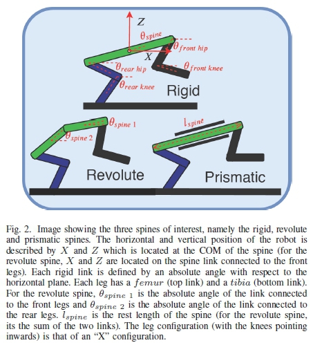
The experimental procedure is similar to [28] with a similar optimization method to the authors previous large-scale Monte Carlo paper [31]. The three spines of interest are shown in Fig. 2. The leg parameters and configuration (forced to an X-type configuration, as seen in Fig. 2) for the three spine morphologies were kept constant.
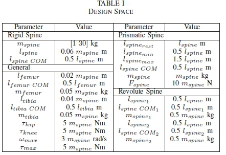
Following our previous study [28], [31], 100 randomly generated robot parameters from the design space, Table I, were used. For an explanation of the symbols, see Fig. 2. In order to improve the chances of generating feasible robots, the parameters were normalized with respect to the spine length to ensure a robot, for example, with a large spine did not have short legs. This limits the design space, but makes this initial study tractable.
To date only a few large-scale Monte Carlo simulations have been attempted using trajectory optimization methods [28], [29], [31], [32]. These have focused on short trajectories [29], [32], enforced a contact order [28] or are using simple models (templates) [32]. Following the results found in [8], whereby it was shown that the optimal method to accelerate and decelerate is to launch straight into the desired velocity/gait, the task was picked as a long-time-horizon task without enforcing a contact order (the optimizer was tasked with determining the optimal gait, instead of enforcing gaits such as the walk or bound, see Section II-A2). The task involved starting and ending at rest, while covering a distance of 30 spine lengths.
Once a random set of parameters was generated, the equations of motion (EoM) for the different spine morphologies were generated using Euler-Lagrange dynamics. The EoM were generated using the manipulator equation as follows:
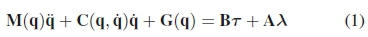
where q are the generalized coordinates (absolute angles relative to the inertial frame), τis the generalized forces and torques and λis the ground reaction forces generated by foot contacts with the ground. M(q) is the mass matrix, C(q, q) is the Coriolis matrix, G(q) is the gravitational matrix, B maps the generalized forces and torques to the generalized coordinates and A maps the ground reaction forces to the generalized coordinates. The generalized forces and torques are dependant on the spine morphology in question. The common generalized coordinates, which are explained in Fig. 2, are:
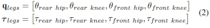
The generalized coordinates, forces and torques:
• Rigid Spine Morphology
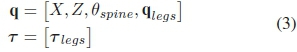
• Revolute Spine Morphology:
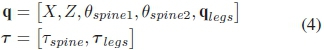
• Prismatic Spine Morphology:
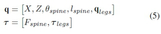
To avoid the biasing effect of designing a controller for each parameter set, optimal control in the form of trajectory optimization was used to select the desired torques to achieve the best trajectory. Trajectory optimization seeks to find a trajectory that satisfies a number of constraints while minimizing a cost function. This is done by varying the decision variables, (6), between their upper and lower bounds. The general framework of the trajectory optimization problem can be found in [33]. The decision variables are as follows:
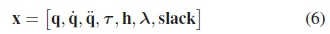
where q and its derivatives, q and q, are the robots generalized coordinates with τbeing the generalized motor torques. The time period between each node point (the trajectory is divided into N node points) is represented by h. The external ground reaction forces (λΧι,λζι,λΧ2,λζ2) experienced during a contact phase is represented by λand there are a number of slack variables (due to the contact-implicit methods implemented in Section II-A2) which ensures these forces only occur when the foot is in contact with the ground.
In an attempt to discover the globally optimal trajectory, 30 seed points were run for each spine morphology and each parameter set with the best solution being taken as the optimal trajectory. The relevant constraints and bounds, along with the problem set-up are detailed below.
A. Constraints
In order to guide the optimizer to a feasible and realizable solution, a number of constraints are applied that must be satisfied before the solution is considered feasible. These constraints are as follows:
1) Collocation: The trajectory is discretized into N1 time periods (called finite elements) using polynomials. Each state trajectory is represented using a Runge-Kutta bases with K-collocation points [34]. For these experiments, 3-point Radau (K = 3, with an accuracy of h2K-1[34]) was used to solve the differential equations, (1), at collocation points [34], [35]. The time step between these finite elements is denoted hiand is constrained between the following bounds:
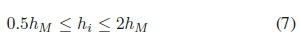
where hiis the time period for the ithnode and hMis set to T/N, where T is the estimate of how long the trajectory should take and N is the number of nodes. T/N acts as a scaling factor for the time bounds. See Section II-C for further details on this.
2) Contact-Implicit Optimization Method: Due to the hybrid nature of the systems being modelled and because we did not want to restrict the search space to a fixed gait pattern, the optimizer was tasked with choosing the optimal foot contact phase order. This was achieved using Contact-Implicit Optimization methods [36], which have been shown to be a vital tool in studying locomotion [37]-[39], and has been implemented with significantly increased accuracy [34]. This method requires a large number of complementary constraints which can be found in [36] equation (8) to (16). All contacts are modelled as an inelastic collision [36], [40] and can take one of two modes (sticking or slipping). Slipping is modelled using a coulomb friction model [36].
These complimentary constraints are inherently difficult to solve and therefore regularization methods [41] were used as follows:
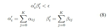
where aij and ßij are the two parts of the complementary constraint for the ithnode and jthcollocation point. These are summed across the collocation points to ensure no discontinuity occurs within the finite element. When solved these complimentary constraints will equal zero (aij ßij =0). Due to the regularization techniques, e starts off large and tends towards zero with every solve iteration (detailed in Section II-C). An example complementary constraint is αrepresenting the vertical ground reaction force and ß representing the vertical height of the foot. As αβ= 0, there can only be a ground reaction force when the foot is on the floor (see [36] for a list of complimentary constraints required).
3) Joint Angles: The generalized coordinates, (2), used are absolute angles, therefore to constrain the motion of the limbs to a feasible range, constraints on the relative angles were enforced. These constraints force the legs to obey the "X" configuration (both knees pointing inwards), as seen in Fig. 2. Similar constraints were applied for the velocity of the limbs. For the revolute spine, constraints were imposed on the spine angle, limiting the relative angle to 30 degrees [6]. These constraints took the following form:
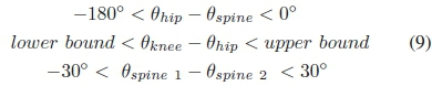
The upper bound for the relative angle for the knee, for the front leg was 0° and for the rear leg was 270°, with the lower bound for the front leg being -270° and for the rear leg being 0°.
4) Motor Model: In order to get a more accurate representation of the applied torques on the quadruped model, a simple motor power model was implemented which limited the total torque available depending on the relative angular rate of the motor as follows [29]:
where τ (i) is one of the applied torques in (2) and ω(ΐ) is the relative rotational velocity of the limb attached to the motor. Tmax(stall torque) and L<jmax(no load speed) are motor parameter constants and can be found in Table I. A similar model is implemented with the force actuator in the prismatic spine (substitute the torque for the force and the angular rate with the linear velocity of the actuator).
5) Terminal Conditions: The terminal conditions (end in a rest configuration, qN= q1, with zero velocity, qN= q 1with q 1=0) were enforced through constraints. These constraints ensured that the robot completed the desired long-time-horizon task by ending at rest after travelling a distance of 30lspine. The rest configuration consists of the robots with a horizontal spine (with the prismatic spine at rest length) and straight, vertical legs with zero velocity.
B. Bounds
The optimizer varies the decision variables, (6), between their bounds to satisfy all the constraints and minimize the cost function. The ground reaction forces were bounded between zero and five times the mass of the robot (0 < λ < 5mrobotg, where g is the gravity constant, 9.81).
The torques and forces are bounded using constraints (motor model constraints, II-A4), however to reduce the search space, these variables were bounded to their max values as seen in Table I. The slack variables were not bounded, however were positive variables (0 < .slack < inf).
The first node point was bounded in such a way that the robot was forced to start in the rest configuration (standing with a horizontal spine, with straight vertical legs and zero velocity).
The generalized coordinates are bounded to ensure that the robot remains in a feasible and realizable configuration. Due to absolute angles being utilized, additional joint constraints are employed to ensure the legs remain in a feasible region. All leg angles are bounded between πand -π, the spine angles are bounded between π/2 and -π/2 (with 0 being horizontal). The other coordinates, such as X and Z (and their velocities) were bounded sufficiently high to restrict the search space, but to not limit the solution space.
The velocity of the generalized coordinates for all the angles are bounded sufficiently high, with constraints on the joint velocities (Section II-A3) limiting the relative velocity (ω„ίαχ) to the values found in Table I.
C. Solver Set-up and Seed Loops
Due to the complexity of the problem that needs to be solved, there is no guarantee that a global optimal solution will be found. Therefore to increase the possibility of finding an optimal solution, 30 optimizations, each with a randomly generated seed point (starting point), was run for each spine morphology for each parameter set. The best solution was then taken as the optimal solution. The problem was a minimum time problem with the cost function, J, as follows:
where hiis the time duration of the ithnode, when summed for all nodes, N, gives the total time of the trajectory. Due to the large number of complementary constraints that need to be solved, regularization techniques [41] were employed. Initially, e was set to 1000 and the problem was solved iteratively, 8 times. After each solve iteration, e was divided by 10. As soon as a solution could not be found, the seed was abandoned and the next seed point was run. After 8 iterations, the complimentary constraints were considered solved (e = E - 4) and the solution was saved. The IPOPT [42] solver was used in GAMS (General Algebraic Modelling System) [43]. The first ten seed points were optimized with T set to 7 seconds, the next ten seeds had T set to 6 seconds and the last ten seeds T was set to 5 seconds. By varying the expected time of the trajectory, it was found to drastically improve the convergence rate across the randomly generated robots.
III. Results
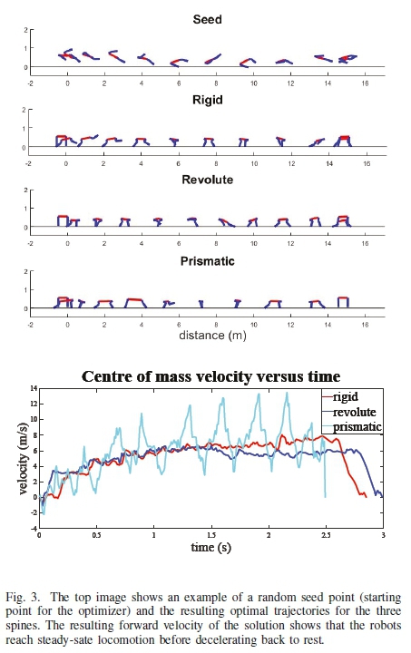
In total 9000 trajectory optimization problems were executed (30 seeds, 100 robots and 3 spines) with an average convergence rate of 19%. This is comparable to previous large-scale trajectory optimization studies [28], [29]. Each successful optimization took between 4 and 5 hours to find an optimal solution (unsuccessful seeds took about an hour before proceeding to the next seed) and was optimized on 12 identical desktop computers (took approximately 2 months to collect the data). Animations of the results can be found here: https://youtu.be/ElBvS13a6pw. As can be seen the robots reach steady-state before decelerating to rest (also shown in Fig. 3). Unlike the previous study [28], this shows that the acceleration and deceleration trajectories start and end in feasible positions and can be implemented on a physical platform.
For each set of robot parameters the optimal trajectory for each spine morphology was calculated by selecting the converged seed that had the fastest time to complete the trajectory. Bootstrapping [30] techniques (with 10 000 iterations of sampling and replacement) were applied and the results can be seen in Table II. The trajectories were also split in two (according to the horizontal position, 0 to 15 spine lengths and 15 to 30 spine lengths) to determine the optimal spine for the acceleration and deceleration portion of the trajectory, also shown in Table II.
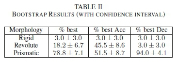
These results reveal that for the full trajectory, there is a 78.8% probability that a prismatic spine is the optima morphology. Specifically, for the acceleration phase, this prob ability is 51.5% while for the deceleration phase it is raise-to 94%.
IV. DISCUSSION
The results demonstrate that a robot with a prismatic spine selected at random will have a 78.8% chance of being the optimal spine morphology for these long-time-horizon maneuvers. The reasons for this will be explored in greater detail below.
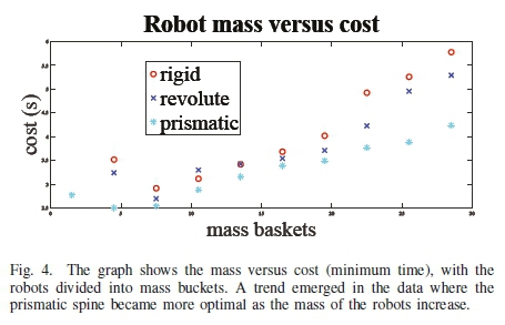
Firstly, the cost (minimum time) versus mass graph for all the optimal results is shown in Fig. 4. A clear trend emerges across the results, revealing that the prismatic spine is by far the most optimal spine over all masses, and becomes more apparent as the robots become heavier.
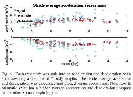
Next the stride frequency and length was analyzed. These parameters were calculated for the trajectory as follows:
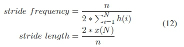
where n is the number of times the rear foot and front foot hit the ground, with  being the time it took to complete the trajectory and the total distance covered in the trajectory is represented by x(N) (30 spine lengths). These results can be seen in Fig. 5. The stride frequency remains roughly constant across mass with the prismatic spine generally having the lowest stride frequency. The stride length increases for mass with the prismatic spine robots having the largest stride length. This matches observations made in nature [2], [6], [7] and shows that the prismatic spine is being used to increase the stride length while keeping the stride frequency constant across different sized robots.
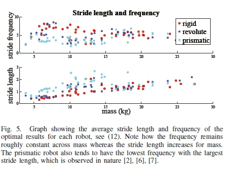
The average acceleration and deceleration, Δx/Δt, was als< analyzed by looking at the first and last 7 body lengths of th trajectory as can be seen in Fig. 6, where Δt was the tim period of the trajectory. It is clear that the prismatic spin robot out performs the other spine morphologies and achieves a much higher average acceleration and deceleration. This is partly due to the prismatic spines ability to increase the stride length during acceleration and to compress and absorb energy during the deceleration phase.
Calculating the work done on forward motion [28], (13), per robot revealed that the prismatic spine exerted, on average, 37% more forward work than the rigid robot and 28% more than the revolute robots.
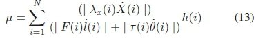
Where λx(i) is the horizontal ground reaction force of the foot on the ground for the ithnode, X(i) is the forward velocity for the ithnode, while the denominator represents the force/torque multiplied by the actuators respective velocity and h(i) is the time duration of the ithnode.
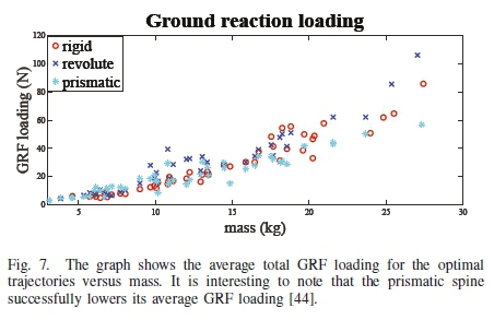
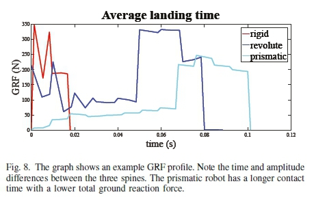
Looking at previous biological studies [44], it has been hypothesized that the average GRF loading can be reduced by using an actuated spine. The average GRF loading for the trajectory was calculated as follows:
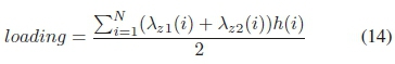
where λz\(i) and λz2(i) are the rear and front vertical ground reaction forces respectively for the ithnode, while h(i) is the duration of time for that node. The results are shown in Fig. 7. It is clear that the average GRF loading is significantly less over the whole trajectory for the prismatic spine. This is vital for protecting the legs during these rapid maneuvers while the average landing time was observed to be longer for the prismatic spine, Fig. 8. This matches observations in nature where it was shown that the cheetah had a longer landing time compared to the slower greyhound [2]. It is hypothesized that the prismatic spine can compress and absorb energy during the impacts, resulting in a reduced peak ground reaction force and a longer contact time.
From analyzing the animations of all the results, a number of trends emerged. When the hind legs land, they begin to swing backwards, while the front legs swing forward. When the front legs land, they swing backwards while the rear legs swing forward, matching what is observed in [45]. For the revolute robots, when the rear leg is on the ground, the spine extends, effectively increasing the stride length and pushes the front legs forward. When the front leg is on the ground the spine contracts, pulling the rear legs forward. This spine motion is observed in [45]. Similar observations were made in the prismatic spine robots. When the rear legs were on the ground, the spine extends and pushes the front legs forward, increasing the stride length. When the front legs were on the ground, the spine would contract pulling in the rear legs.
During acceleration, the prismatic spine first contracts to pull in the rear legs and then begins to accelerate, compared to the revolute spine which slightly bends its spine and then starts accelerating. It is hypothesized that this is the reason the prismatic spine is only optimal 51.5% for rapid acceleration only, as pulling in the rear legs takes time. It is proposed to start the prismatic robots with their spines fully contracted to improve its acceleration performance, or optimize only the acceleration phase. The prismatic spine robots also reach a higher top speed. During deceleration, the spine contracts and absorbs the momentum to stop the robot, whereas the rigid and revolute robots tend to slide to a stop and purely rely on friction.
V. Conclusion and Future Work
From the results and discussion it is evident that the prismatic spine is the optimal spine morphology for these high-speed transient motions. The prismatic spine successfully increases the stride length while roughly keeping the stride frequency the same. Therefore, in order to improve the agility and performance of robots, designers of new quadruped robots should utilize a prismatic spine morphology.
Future work will involve extending this research to three dimensions with a two DOF spine and 4 legs.
References
[1] A. A. Biewener and S. N. Patek, "Animal Locomotion," Oxford University Press, 2003.
[2] P. E. Hudson, S. A. Corr and A. M. Wilson, "High speed galloping in the cheetah (Acinonyx jubatus) and the racing greyhound (Canis familiaris): spatio-temporal and kinetic characteristics," Journal of Experimental Biology, vol. 215, no. 14, pages 2425 to 2434, 2012. [ Links ]
[3] Cheeetah Running, [Online] https://youtu.be/mufJyH7qRpI, Accessed 21 February 2019.
[4] R. Walter and D. Carrier, "Rapid acceleration in dogs: ground forces and body posture dynamics," The Journal of Experimental Biology, 2009.
[5] R. Gillette and T. Angle, "Recent developments in canine locomotor analysis: A review," The Veterinary Journal, vol. 178, 2008. [ Links ]
[6] M. Hildebrand, "Motions of the running cheetah and horse," J. Mammal.,, vol. 40, no. 4, pp. 481-495, 1959. [ Links ]
[7] M. Hildebrand, "Further studies on locomotion of the cheetah," J. Mammal., vol. 42, no. 1, pp. 84-91, 1961. [ Links ]
[8] C. Fisher, C. Hubicki and A. Patel, "Do Intermediate Gaits Matter When Rapidly Accelerating?" IEEE Robotics and Automation Letters, vol. 4, no. 4, 2019. [ Links ]
[9] J. Duperret and D Koditschek, "Empirical validation of a spined sagittal-plane quadrupedal model," IEEE International Conference on Robotics and Automation (ICRA), 2017.
[10] D. Kuehn, A. Dettmann and F Kirchner, "Analysis of using an active artificial spine in a quadruped robot," in 2018 4th International Conference on Control, Automation and Robotics (ICCAR), pp. 37-42, 2018.
[11] S. Seok, A. Wang, M. Chuah, D. Hyun, J. Lee, D. Otten, J. Lang and S. Kim, "Design principles for energy efficient legged locomotion and implementation on the MIT cheetah robot," IEEE/ASME Transactions on Mechatronics, vol. 20, no. 3, pp. 1117-1129, 2015. [ Links ]
[12] J. Pusey, J. Duperret, G. Haynes, R. Knopf and D. Koditschek, "Freestanding leaping experiments with a power-autonomous elastic-spined quadruped," International Society for Optics and Photonics in Unmanned Systems Technology XV, vol. 8741, 2013. [ Links ]
[13] M. Khoramshahi, A. Sprowitz, A. Tuleu, M. Ahmadabadi and A. Ijspeert, "Benefits of an active spine supported bounding locomotion with a small compliant quadruped robot," In IEEE International Conference on Robotics and Automation (ICRA), 2013.
[14] Y. Kajiwara, S. Ikemoto, and K. Hosoda, "Pneumatically-driven Quadruped Robot with Biomimetic Legs and Flexible Spine," Procedure ofInternational Symposium on Adaptive Motion in Animals and Machines, vol. 23, 2017. [ Links ]
[15] D. Kuhn, A. Dettmann and F. Kirchner, "Analysis of using an active artificial spine in a quadruped robot," 4th IEEE International Conference on Control, Automation and Robotics (ICCAR), 2018.
[16] S. Bhattacharya, et al. "Learning Active Spine Behaviors for Dynamic and Efficient Locomotion in Quadruped Robots," arXiv preprint arXiv:1905.06077 (2019).
[17] M. Kani, M. Derafshian, H. Bidgoly and M. Ahmadabadi "Effect of flexible spine on stability of a passive quadruped robot: Experimental results," In 2011 IEEE International Conference on Robotics and Biomimetics (ROBIO), pp. 2793-2798, 2011.
[18] Q. Cao and I. Poulakakis, "Passive stability and control of quadrupedal bounding with a flexible torso," IEEE/RSJ International Conference on Intelligent Robots and Systems (IROS), 2013.
[19] G. Haynes, J. Pusey, R. Knopf and D. Koditschek, "Dynamic bounding with a passive compliant spine," In Proc. Dynamic Walking Conf, 2012.
[20] K. Koutsoukis and E. Papadopoulos, "On passive quadrupedal bounding with translational spinal joint," in IEEE/RSJ International Conference on Intelligent Robots and Systems (IROS), 2016.
[21] Q. Liu, Y. Bao, W. Yu, J. Zhang, C. Li, and X. Xie, "Mechanism of Spine Motion About Contact Time in Quadruped Running," Chinese Journal ofMechanical Engineering, vol. 32, no.1, 2019. [ Links ]
[22] B. Ponton, F. Farshidian, and J. Buchli, "Learning compliant locomotion on a quadruped robot," IROS Workshop (Ed.), Compliant manipulation: Challenges in learning and control. 2014.
[23] S. Talebi, I. Poulakakis, E. Papadopoulos and M. Buehler, "Quadruped robot running with a bounding gait," In Experimental Robotics VII, pp. 281-289, Springer, Berlin, Heidelberg, 2001.
[24] K. Koutsoukis and E. Papadopoulos, "Comparing the Effects of Revo-lute and Prismatic Spinal Joint on Quadrupedal Bounding," School of Mechanical Engineering, National Technical University of Athens.
[25] P. Eckert, A. Sporwitz, H. Witte and A. Ijspeert, "Comparing the effect of different spine and leg designs for a small bounding quadruped robot," In IEEE International Conference on Robotics and Automation (ICRA), pp. 3128-3133, 2015.
[26] A. Sabelhaus, A. Akella, Z. Ahmad and V. SunSpiral, "Model-Predictive Control of a flexible spine robot," IEEE American Control Conference (ACC), 2017.
[27] A. Sabelhaus, et al. "Design, Simulation, and Testing of a Flexible Actuated Spine for Quadruped Robots," arXiv preprint arXiv:1804.06527 (2018).
[28] C. Fisher, S. Shield and A. Patel, "The effect of spine morphology on rapid acceleration in quadruped robots," in IEEE/RSJ International Conference on Intelligent Robots and Systems (IROS), 2017.
[29] M. Haberland and S. Kim, "On extracting design principles from biology: II. Case study-the effect of knee direction on bipedal robot running efficiency," Bioinspiration & Biomimetics, vol. 10, no. 1, 2015. [ Links ]
[30] M. Haberland and S. Kim, "On extracting design principles from biology: I. MethodGeneral answers to high-level design questions for bioinspired robots," Bioinspiration & biomimetics, vol. 10, no. 1, 2015. [ Links ]
[31] L. Raw, C. Fisher and A. Patel, "Effects of Limb Morphology on Transient Locomotion in Quadruped Robots," In IEEE/RSJ International Conference on Intelligent Robots and Systems (IROS), 2019.
[32] J. Yu, D. Hong and M. Haberland, "Energetic Efficiency of a Compositional Controller on a Monoped With an Articulated Leg and SLIP Dyanmics," In IEEE/RSJ International Conference on Intelligent Robots and Systems (IROS), pp. 2221-2228, 2018.
[33] M. Kelly, "Transcription Methods for Trajectory Optimization, A beginners tutorial," Cornell University, 2015.
[34] A. Patel, S. Shield, S. Kazi, A. Johnson and L. Biegler, "Contact-Implicit Trajectory Optimization using Orthogonal Collocation," Robotics and Automation Letters, 2019.
[35] L. Biegler, Nonlinear programming: concepts, algorithms, and applications to chemical processes. SIAM, 2010, vol. 10.
[36] M. Posa, C. Cantu and R. Tedrake, "A direct method for trajectory optimization of rigid bodies through contact," The International Journal of Robotics Research, vol. 33, no. 1, pp. 69-81, 2014. [ Links ]
[37] S. Shield and A. Patel, "Balancing stability and maneuverability during rapid gait termination in fast biped robots," In IEEE/RSJ International Conference on Intelligent Robots and Systems (IROS), 2017.
[38] A. Blom and A. Patel, "Investigation of a Bipedal Platform for Rapid Acceleration and Braking Manoeuvres," In 2018 IEEE International Conference on Robotics and Automation (ICRA), 2018, pp. 426-432.
[39] N. Doshi, K. Jayaram, B. Goldberg, Z. Manchester, R. Wood and S. Kuindersma, Contact-Implicit Optimization of Locomotion Trajectories for a Quadrupedal Microrobot, Robotics: Science and Systems (RSS), 2018.
[40] J. Yu, D. Hong and M. Haberland, "Energetic Efficiency of a Compositional Controller on a Monoped with an Articulated Leg and SLIP Dynamics," In IEEE/RSJ International Conference on Intelligent Robots and Systems (IROS), 2018.
[41] D. Ralph and S. Wright, "Some properties of regularization and penalization schemes for MPECs," Optimization Methods and Software, vol. 19, no. 5, pp. 527-556, 2004. [ Links ]
[42] A. Wachter and L. Biegler, "On the Implementation of a Primal-Dual Interior Point Filter Line Search Algorithm for Large-scale Nonlinear Programming," Mathematical Programming, vol. 106, no. 1, pp. 25-57, 2006. [ Links ]
[43] GAMS Development Corporation, "Generic Algebraic Modeling System (GAMS)," 24.4.6, Washington, DC, 2015.
[44] T. Kamimura, S. Aoi, K. Tsuchiya and F. Matsuno, "Body flexibility effects on foot loading in quadruped bounding based on a simple analytical model," IEEE Robotics and Automation Letters, 2018.
[45] K. Zhang and B. Wang, "Analysis of CPG gait parameters and velocity of quadruped robot with spine," 2018 Australian & New Zealand Control Conference (ANZCC), IEEE, 2018.
Manuscript received April 19, 2021
Revised April 19, 2021
Callen Fisher just received his PhD in the department of Electrical Engineering at the University of Cape Town. Dr. Fisher is now a lecturer at Stellenbosch University and is currently focused on bio-inspired robotics.

Amir Patel received his PhD in Mechatronics Engineering at the University of Cape Town, South Africa in 2015. He is currently an Associate Professor in the Department of Electrical Engineering and his research focus is on legged maneuverability in animal and robotic systems.
This work is based on the research supported in part by the National Research Foundation of South Africa for the Grant No. 117744 and 116415.
1 discretized into N = 300 time periods

