


Services on Demand
Article
 English (pdf)
 Article in xml format
 Article references
Indicators

Related links
-
 Cited by Google
 -
 Similars in Google
Share

 Permalink
SAIEE Africa Research Journal
On-line version ISSN 1991-1696
Print version ISSN 0038-2221
SAIEE ARJ vol.112 n.1 Observatory, Johannesburg Mar. 2021
ARTICLES
Performance Study of Path Loss Models at 14, 18, and 22 GHz in an Indoor Corridor Environment for Wireless Communications
Mohamed K. ElmezughiI; Thomas J. AfulloII; Nicholas O. OyieIII
IDiscipline of Electrical, Electronic & Computer Engineering, School of Engineering, Howard College Campus, University of KwaZulu-Natal, Durban, South Africa (e-mail: m.k.elmezughi@gmail.com). Student Member, IEEE
IITelkom Centre of Radio Access & Rural Technologies, Discipline of Electrical, Electronic & Computer Engineering, School of Engineering, Howard College Campus, University of KwaZulu-Natal, Durban, South Africa (e-mail: afullot@ukzn.ac.za). Senior Member, IEEE
IIIDiscipline of Electrical, Electronic & Computer Engineering, School of Engineering, Howard College Campus, University of KwaZulu-Natal, Durban, South Africa (e-mail: noyie@mmust.ac.ke). Member, IEEE
ABSTRACT
The critical rule to achieve extremely high peaks of data transmission is the availability of a tremendous amount of bandwidth. The super high frequency (SHF) and the millimeter-wave (mmWave) frequency bands are the candidates for the deployment of the 5C cellular system and for satisfying future needs due to their massively available blocks of contiguous raw bandwidth that is capable of supporting additional data traffic for multimedia services. This research paper presents propagation measurements at three frequencies above 6 GHz, which are 14, 18, and 22 GHz frequency bands. The measurements were carried out for both line-of-sight (LOS) and non-line-of-sight (NLOS) communication scenarios in an indoor corridor environment to present frequency- and distance-dependent wireless channel models. Moreover, this study presents, investigates, and compares the performance of two well-known path loss prediction models; the single frequency close-in (CI) free space reference distance model and the single frequency floating intercept (FI) model. The LOS comparison study shows that the CI and FI models provide comparable and accurate estimates that fit the real measured data for the frequency bands selected. Furthermore, the study investigates the behavior of the path loss exponent (PLE) and the FI model parameters as a function of the reception angle of arrival (AoA) in the NLOS scenario. It is observed from this work that the path loss models' parameters exhibit symmetrical behavior around 180° AoA. The FI model provides the same standard deviation values as the CI model in the LOS scenario. In contrast, the FI model offers a notable reduction (up to 2.84 dB) compared to the CI model in the NLOS scenario.
Finally, the LOS and NLOS results reveal that the CI and FI models can be trusted as good path loss models for corridor environments and exhibit stable behavior over measured distances and frequencies.
Index Terms:SHF, mmWave, channel sounder, directional antennas, angle of arrival, indoor corridor environment, path loss models, propagation measurements, 14 GHz, 18 GHz, 22 GHz.
I. Introduction
THE availability of a tremendous frequency spectrum is at the head of the reasons for achieving extremely high-speed communication services. Hence, the vital resource and the access factor for the fifth-generation mobile system (5G) and any other mobile access networks are quantity, quality, and efficiency of using the amount of the available spectrum [1], [2].
The main problem in the frequency bands below 6 GHz is the scarcity in the bandwidth. Accordingly, this lack of bandwidth will not meet the aspirations of the upcoming 5G wireless system to accomplish high peak data transmission rates up to multi gigabits per second even with complex modulation schemes and multiple-input multiple-output (MIMO) systems [1]-[13]. Because of that and due to the rapid growth in demand for much higher data rates, the research on the millimeter-wave (mmWave) frequency spectrum (30-300 GHz) has been accelerated for the reason that these bands are the candidate for deployment of the 5G cellular network and for satisfying future needs [2], [4]-[7].
The mmWave frequency regime has massively available blocks of contiguous raw bandwidth that is capable of supporting more data traffic for various multimedia services [1]-[20]. Nevertheless, the 5G system will still have access to the licensed spectrum in the higher centimeter wave (cmWave) bands. The super high frequency (SHF) spectrum (3-30 GHz) and the extremely high frequency (EHF) spectrum (well known as millimeter-wave bands) have comparable propagation characteristics and behavioral attributes, both accordingly known as mmWave [1], [12], [21].
The potential frequency spectrum that will be used in the 5G wireless system is up to 100 GHz. One of the reasons for this is that it is presumed that the reach of mass-market semiconductor technology expands up to approximately 100 GHz. However, it is bound to pass that limit in time [3].
The mmWave regime provides a bandwidth higher than 400 MHz over commercial applications, which is extremely large compared to today's 4G long-term-evolution (LTE) 20 MHz cellular channels [16], [22]. Assuredly, the mmWave frequency spectrum plays an essential role in 5G wireless communications [1], [14].
The 5G mmWave frequency bands have the opportunity to support such throughput data rates for low latency content, high-definition (HD) video, virtual interaction between people and machines, and other applications that require extremely high data rate transfer [1], [20], [23].
Until recently, the frequency bands below 6 GHz have been considered for mobile systems due to their capability to support broad area coverage (up to several kilometers) and the ability to penetrate readily through buildings. On the other hand, mmWave bands support much smaller area coverage (cell radius is a few hundred meters) because the propagation of the mmWave is profoundly affected by the environment where the signal propagates. Furthermore, the penetration loss through solid materials significantly affects the mmWave frequency spectrum [3], [17]. Hence, accurate understanding and characterization of behaviors of the mmWave frequency bands in numerous indoor and outdoor environments and scenarios are fundamental for performance analysis and reliable deployment of the 5G cellular systems [13], [15], [18], [19].
Because mmWave signals have a severely limited range, hotspot cells will need to become the focus of future mobile applications in both urban and suburban environments. The small cell radius will be between 100 and 500 meters in outdoor urban areas at the mmWave frequency bands [16]. Consequently, the cell coupling range and the path loss values will change quickly. The characteristics of mmWave signals can allow for more efficient use of spectra and can increase the security of communication transmission [17].
Path loss is a significant problem in the design and analysis of the link budget and signal strength prediction of any communication system. It represents the reduction of the signal power as it propagates from the transmitter to the receiver through the transmission channel. Path loss immensely affects the data rate and signal-to-noise plus interference ratio (SNIR); therefore, the network coverage area will be affected. Hence, mmWave system simulations require reliable path loss models for the reason that it is the primary parameter in wireless propagation channel modeling [1].
Path loss models can be classified into two types; the first one depends on a physical anchor that catches path loss near the transmitter (Tx), e.g., the CI model and CI model with frequency-dependent path loss exponent (CIF). The second one mainly depends on the mathematical curve or surface that fits the measured data, e.g., the FI and Alpha-Beta-Gamma (ABG) models [13].
Large scale path loss models are essential to characterize and model the propagation channel over distance and frequency for reliable system design. In order to achieve that, many measurement campaigns have been conducted to present and develop path loss models based on the real measured data collected at various environments and scenarios at different mmWave frequency bands [24]-[73].
A large-scale path loss prediction model based on measurements for both LOS and NLOS conditions were detailed in [1] at 14 and 22 GHz frequency bands in an indoor corridor scenario. In this paper, based on real measured data collected, a simple and reliable single-frequency DS large-scale path loss model is presented. The outcome shows that the DS path loss model outperforms the CI model in all the scenarios and frequency bands. Furthermore, the standard deviation values of the shadow fading for the presented DS large-scale path loss model were smaller than the values recorded for the CI model; consequently, more precise in predicting the path loss. Additionally, the presented model studied modal attenuation as a result of multipath and propagating waveguiding effect in indoor corridors. These corridors are considered as oversized dielectric waveguides with transversal dimensions much more abundant than the wavelength of the signal transmitted; hence several modes are heavily involved in the propagation process. The study examined two essential aspects of a corridor typical model propagation phenomenon, which are waveguiding effects in a corridor and breakpoint. Accurate path loss models are essential for indoor corridor environments in the candidate mmWave regime for applications in future generation communication systems [20]. The 5G networks will rely on the LOS probability in terms of the coverage capability in indoor corridor environments [19].
Omnidirectional path loss models and LOS probability based on real measured data were presented in [19] for an indoor corridor environment at 18 GHz frequency band where the transmitting and receiving antennas had no obstacle between them and pointed toward each other with alignment on boresight (i.e., LOS scenario). The study compared two empirical path loss models, i.e., the CI and DS models. The proposed models address the deficiencies of the existing models in terms of reliability and accuracy. The study covered the effect of the building's structure and material used on the proposed omnidirectional path loss and LOS probability in the corridor environment since they are essential aspects for indoor propagation characteristics as they determine the overall network coverage capacity. Moreover, the proposed models take into account the propagation mechanisms such as diffraction and reflection in an indoor corridor, resulting in modal propagation. The CI model was determined by determination of the PLE while the DS model determination was based on two PLEs, one of them before the break-point and other after the break-point. Both models found the PLEs based on the minimum mean square error (MMSE) method to minimize the standard deviation [70]. Also, the MMSE technique was adopted for the optimal parameterization of LOS probability models. The results showed that the DS omnidirectional path loss model outperforms the well-known CI model and presents a better path loss prediction model for 5G network deployment in indoor corridor environments. Besides, the presented DS path loss model considers whether the modal attenuation factor (MAF) value was determined following the structural design of the indoor corridor environment. The study also showed that the PLE drops by 4 dB per decade of distance for the DS model after the breakpoint while remains constant at 6 dB for the CI model. Furthermore, the proposed LOS probability model outperforms the existing WINNER II (A1) models and the ITU Recommendation (ITU-R) model. For corridor environments, the error margin of the proposed model was 0.81%, while it equals to 1.21% and 1.76% in WINNER II (A1) and ITU-R models, respectively. The LOS probability is crucial for establishing system coverage ability. Characterizing and modeling the propagation of mmWave signals in indoor corridor environments are essential steps in developing mobile access networks for 5G systems.
A performance study of multi-frequency path loss prediction models at 14 to 22 GHz bands based on the DS and ABG was performed [20]. The models take into consideration the modal attenuation of signal strength as it is guided along the indoor corridors. The environments were two indoor corridors with different materials; one of them is a glass-based corridor, and the other one is a concrete corridor. The LOS scenario in this effort was established when there was no obstacle between the Tx and Rx, and both antennas were aligned toward each other. The NLOS scenario was created when the antennas had no barrier between them. However, they were out of alignment on boresight so that the receiver had to rely primarily on the reflected paths since diffraction plays a lesser role in the mmWave spectrum [72], [73]. The path loss models used in this effort considered the propagation mechanisms such as reflection and diffraction. It is observed in this effort that the DS model is accurate and straightforward, hence suitable for systems design for indoor environments. Also, the study results seemed to give a more reliable prediction of path loss over the ABG model as matched to the real measurement data and have lower standard deviation values for LOS and NLOS in all indoor environments. The effort also showed that when the transmitting and receiving antenna heights are equal, the PLE values before the break-point is approximately the same (1.7 to 1.8 for the LOS scenario, and 2.5 to 2.7 for the NLOS scenario) for the concrete and glass corridors. The PLE value after the break-point was equal for both the DS and ABG models in the
LOS scenario. Besides, the standard deviation for the DS and ABG models for the same antennas height in the LOS scenario was 1.7 and 1.3, respectively. For different transmit antenna heights, the PLE value was -0.9 and -0.2 the DS model before the break-point in the LOS and NLOS scenarios, respectively. The reason behind this is that the signal level decreases gradually as it is guided along the corridor up to break-point. The work also showed that the maximum observable values of the PLE are 1.8 and 2.7 for LOS and NLOS in the indoor corridors, respectively, these values being compatible with other work [70]. Besides all the works mentioned above and references therein, many additional communication scenarios should be investigated by propagation measurements covering all the candidate mmWave bands to achieve reliable models for the 5G wireless networks.
This submission expands further on the work by Oyie and Afullo [1], which focuses on presenting a dual-slope (DS) path loss model and compares its performance with the close-in (CI) free space reference distance model in an indoor corridor environment at 14 and 22 GHz. This paper presents a performance study to investigate the behavior and propagation characteristics of the floating-intercept (FI) and the CI path loss prediction models. The study is based on real measured data taken from line-of-sight (LOS) and non-line-of-sight (NLOS) propagation measurements that have been conducted at 14, 18, and 22 GHz frequency bands in an indoor corridor environment. Moreover, the path loss exponent of the CI model and the FI model's parameters are presented as a function of the angle of arrival (AoA) for the NLOS communication scenario in an indoor corridor environment at 14, 18, and 22 GHz frequency bands. Also, a comparative study between the path loss models at these bands is presented for the LOS scenario. This study is performed based on real measured data collected in the Discipline of Electrical, Electronic, and Computer Engineering Department, Howard College Campus, University of KwaZulu-Natal, Durban, South Africa.
The rest of this paper is organized as follows. In section II, related works in this field of study for indoor and outdoor wireless channel measurements and modeling are introduced and discussed. The measurements setup and environment are given in section III. Section IV presents and describes the path loss prediction models adopted. The results and discussions of the LOS comparative study between the path loss models and NLOS performance study of the models' parameters are presented in Section V. Finally, Section VI draws the main conclusions of this research.
II. MEASUREMENTS SETUP AND ENVIRONMENT
This section presents a detailed description of measurement campaigns that were carried out on the 5 th floor of the Discipline of Electrical, Electronic, and Computer Engineering Department, Howard College Campus, University of KwaZulu-Natal, Durban, South Africa.
A. Channel Sounder and Measurements Setup
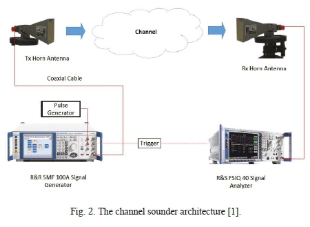
The channel sounder used in the measurements was based on Rohde and Schwarz SMF 100A for Radio Frequency Signal Generator for generating continuous-wave (CW) radio signals at the transmitter (Tx) side and transmitting them through the wireless channel. This signal generator has a working frequency range between 100 KHz and 22 GHz. The receiving equipment utilized was Rohde and Schwarz FSIQ 40 Signal Analyzer at the receiver (Rx) side to receive the continuous signals transmitted by the signal generator. This receiving equipment has a working frequency range of 20 Hz to 40 GHz and a maximum analysis bandwidth of 120 MHz. Fig. 2 represents the channel sounder used in the measurement campaign [1].
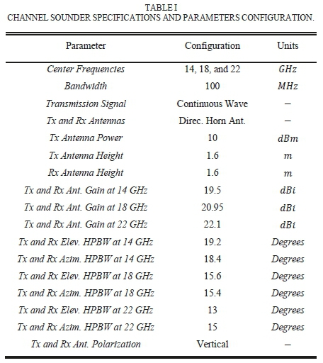
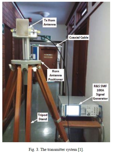
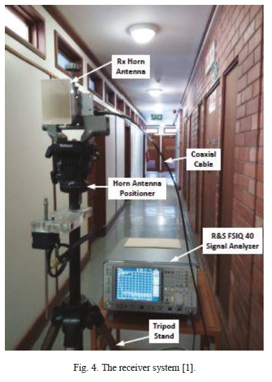
The transmitting and receiving of the wireless radio frequency signals were done by two identical wideband high-gain directional steerable pyramidal horn antennas. The antennas have a directional gain with respect to the isotropic antenna (dBi) at 14, 18, and 22 GHz of 19.5, 20.95, 22.1 dBL respectively. The half-power beam width (HPBW or 3 dB beamwidth) at 14 GHz band is 19.2° in the elevation plane and 18.4° in the azimuth plane; while in the 18 GHz band, these are 15.6° and 15.4°, respectively. In the 22 GHz band, the HPBW values of the horn antennas were 13° in the elevation plane and 15° in the azimuth plane. The measurements have been carried out when the transmitting antenna has heights of 1.6 and 2.3 meters above floor level, whereas the receiving antenna has a height of 1.6 m. This paper considered the data when the antennas are at the same height (1.6 meters above the floor level) for both LOS and NLOS measurements. Table I provides a detailed description of the equipment specifications and parameter configurations for the measurement campaigns. Fig. 3 and Fig. 4 represent the transmitter and receiver adopted,
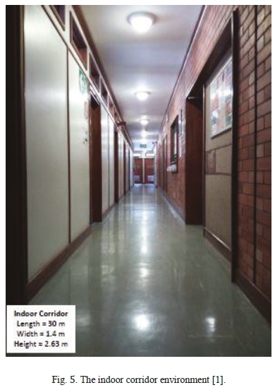
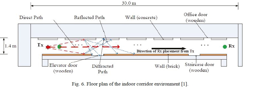
The measurement environment for both the LOS and NLOS scenarios of this study was an indoor corridor, like an oversized air-filled rectangular waveguide with dimensions much greater than the wavelength of the transmitted signals. This corridor is made of dry concrete and bricks and includes a staircase, elevator, and wooden doors to offices. The corridor adopted has a size of 30 m (length) x 1.4 m (width) x 2.63 m (height). Fig. 5 represents the indoor corridor environment used in this study. The measurement campaigns have been carried out in this indoor corridor environment for both LOS and NLOS measurement scenarios.
The transmitting antenna was fixed at one end of the corridor at 0° at both azimuth and elevation plans, and the receiving antenna was moved away from the Tx with 2 m incremental steps per measurement location from 2 to 24 m as a separation distance between the Tx and Rx (13 locations for the LOS and NLOS). For the LOS scenario, the transmit and receive antennas were aligned on boresight with no obstacles between them, whereas in the NLOS scenario still no obstacles in the propagation path between the Tx and Rx, but the antennas had no alignment on boresight and receiving antenna was rotated mechanically in the azimuth plane by 10° steps for the NLOS scenario at each separation distance between the Tx and Rx enabled 36 different AoAs over the 360° azimuth plane while in the elevation plane the AoA was fixed at 0°. In the NLOS measurements, the receiver relying mainly on the reflection and diffraction mechanisms to detect the wireless signals. For all frequency bands used in these measurement campaigns (14, 18, and 22 GHz), vertically polarized identical horn antenna have been utilized. The CW signals transmitted by the Tx at 10 dBm signal level through the corridor environment (wireless channel) via LOS (direct) and NLOS (through reflection, refraction, and/or diffraction), and the reception of these signals was done by the Rx recording 500 data sets of power levels per every Tx-Rx separation distance and every AoA. These signal levels were averaged to have one reliable received power for every single Rx location and every AoA for both LOS and NLOS communication scenarios. The Received power was converted to real measured data of path loss considering the value of Tx power, transmitting and receiving antenna gains, and losses of the connectors such as coaxial cables connecting the equipment to the antenna at both Tx and Rx sides. Note that the NLOS communication scenario in this work was established when the Tx and Rx antennas not aligned on boresight, but there were no obstacles between them. Fig. 6 represents the floor plan of the indoor corridor environment adopted. More information about these measurement campaigns can be found in [1], [19], [20].
III. PATH LOSS PREDICTION MODELS
Path loss is an important component of any communication system's design and analysis of the path budget and signal strength prediction. The path loss reflects a decrease in signal power as it travels through the transmission channel from the transmitter to the receiver. The SNIR and data rates are greatly affected by the path loss; thus, the area of network coverage will be affected. However, mmWave system simulations need accurate models of path loss because this is the primary parameter in the modeling of wireless propagation channels [1].
There are various types of large-scale path loss models (stochastic, deterministic, and empirical models). Nevertheless, the wireless channel's propagation characteristics are reliably calculated by the measurement-based path loss models [12], [70], [74].
The free space path loss between two LOS aligned isotropic antennas depends on the Tx-Rx separation distance and the operating frequency as expressed in absolute numbers by the following equation [75]
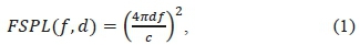
where FSPL is the free space path loss expressed in dB, d is the separation distance between the Tx and Rx in meters, ƒ is the operating frequency in hertz, and c is the speed of light at free space, which is approximately 3 x 10⁸m/s. After converting the previous equation to decibel units, the free space path loss is given by [75]

The units of operating frequency and Tx-Rx separation distance in Eq. 2 are GHz and m, respectively. For a single frequency path loss models when taking into account the type of antennas used and the propagation mechanisms that affect the wireless signal, the path loss is not exactly proportional to the square of Tx-Rx separation distance. However, the path loss can be assumed to have a linear dependence with logarithmic distance as in the following equation [75]
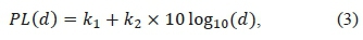
where PL (d) denotes the path loss value as a function of the link distance (d), k1and k2are coefficients in dB and unitless, respectively. These coefficients describe the path loss behavior with the frequency and Tx-Rx separation distance. Depending on several techniques and ideas to find the values of the coefficients /qand k2to fit the real measured data for such environments and scenarios. In general, the relative path loss in the NLOS case is greater than the LOS, and the path loss slope is also increased. The path loss prediction models defined and studied in this section are single-frequency models, which are the CI model, and the FI model. The values of path loss can be calculated theoretically by knowing the transmitted power, transmitting and receiving antenna gains, and the real received signal levels at the Rx side according to the following equation

here Ptis the transmitted power in dBm, Pris the received signal level in dBm, and Gtand Grare the transmit and receive antennas gain in dBi, respectively. The values of Prare taken from the average of several received signal levels detected by the signal analyzer adopted in the measurement campaigns. The following two subsections introduce in some detail of the CI and FI large-scale path loss prediction models.
A. The CI Path Loss Prediction Model
The CI path loss prediction model is a model that depends on only one parameter that characterizes the dependence of the path loss on the 3D separation distance between the transmitter and the receiver. This parameter is called Path Loss Exponent (PLE), usually denoted by n. The value of this parameter changes with the environments and scenarios where the signal propagates. The CI model utilizes a physically-based reference distance. The value adopted for this work is 1 m. Standardizing the CI model's reference distance makes it easy to compare different frequency bands and other researchers' measurements and allows for closed-form computing in the analysis [12]. Also, the motivation for using 1 m as a reference distance for both LOS and NLOS scenarios in the measurement campaigns is the fact that the mmWave bands exhibit a substantial variety in the path loss values in the first meter of propagation away from the transmitter [12]. The equation of the well-known CI path loss model is given by Eq. 5 [75]

where PLa(d) is the path loss in dB at frequency f as a function of the separation distance (d) between the transmitter and receiver, d is the 3D Tx-Rx separation distance (have to be greater than 1 τη), ηis the PLE which is a coefficient that characterizes the dependency of the path loss on the distance, Χσis a Gaussian distributed random variable with zero mean and standard deviation σin dB that represents the SF [76], [78]. Shadowing defines the large-scale signal fluctuations of the models of large-scale path loss over the propagation distance caused by obstructions and other random propagation effects [77]. For researchers and engineers, the importance of the shadow fading lies in the fact that it can develop standards that provide large-scale fading statistical models without in-depth knowledge of the details of a site-specific environment [10]. The term in the previous equation represents the free space path loss expressed in dB; this value can be found at the operating frequency ƒ and 1 m separation distance, the values of FSPL (f, 1m) are calculated by Eq. 6
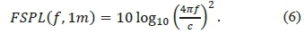
The value of the FSPL(f,1m) ranges from 32 to 72 dB when the operating frequency ranges between 1 and 100 GHz, respectively. The CI model has an intrinsic dependency on the carrier frequency in the FSPL term. This model has a suitability for both single- and multi-frequency cases. Moreover, the CI path loss model can be used to estimate path losses from either co-polarization or cross-polarization or measurements, for a generalized data set that incorporates both cross-polarized and co-polarized (combined polarized) measurements (as in a functional cellular network with random device orientations) [70]. Note that the CI model is one of path loss models that depends on a physical anchor that catches path loss near the transmitter.
As mentioned above, the CI model has one parameter (PLE) that characterizes the losses at distances greater than the reference distance. This parameter needs to be optimized. The estimation of this parameter's value was done using the MMSE technique. The MMSE approach fits the real measured data with the least error (by minimizing the value of σ) utilizing the actual physical anchor point representing the power transmitted from the Tx antenna to the close-in reference distance [70]. To have the closed-form solutions for the PLE and the minimum
SF standard deviation of the CI path loss prediction model in Eq. 5, assume that

Then, the SF in Eq. 5 can be expressed as
Using the MMSE approach, the standard deviation of the SF is given by
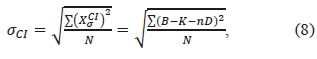
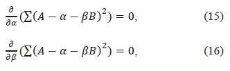
where Νis the number of the Tx-Rx separation distances (from the measurement campaign, Ν = 13). To have the optimum value of the PLE and σα, the partial derivative of the numerator of Eq. 8 with respect to the PLE should be equal to zero. Then
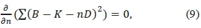
after the derivative and simplification, the closed-form of the PLE can be written as
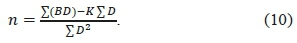
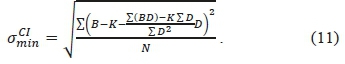
Finally, the best fit minimum value of the SF standard deviation is given by
B. The FI Path Loss Prediction Model
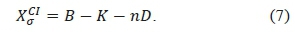
The FI path loss prediction model is a common model that depends on two parameters (a and β) and does not depend on a physical anchor that catches path loss near the transmitter. It depends mainly on the mathematical curve or surface that fits the real measured data. The values of the parameters of this model change with the environments and scenarios where the signal propagates. This model has been widely used in 3GPP and WINNER II standards [48], [70], [78]. The equation of the FI path loss model is given by Eq. 7 [75]

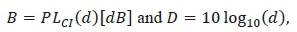
where PLFl (d) is the path loss in dB at frequency ƒ as a function of the separation distance between the transmitter and receiver, d is the 3D Tx-Rx separation distance, a is the floating intercept (unlike the FSPL) in dB, βis the slope of the line (unlike the PLE) that characterizes the dependency of the path loss on the distance, and Χζ' is a Gaussian distributed random variable with zero mean and standard deviation aFlin dB that represents the SF large-scale signal fluctuations over the propagation distance. The parameter βis equal to the PLE if and only if a equal to the value of FSPL at the reference distance (d0). Note that the Eq. 7 requires two parameters (a and β) to be optimized. The estimation of these parameters' values has been done using the MMSE technique to fit the real measured data with the least error (by minimizing the value of σ). To have the closed-form solutions for α, β, and the minimum SF standard deviation of the FI path loss prediction model in Eq. 12, assume that
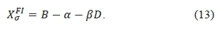
then, the SF in Eq. 12 can be expressed as
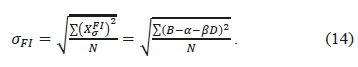
Using the MMSE approach, the standard deviation of the SF is given by
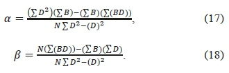
To have the optimum value of the parameters α, β, and σρι, the partial derivative of the numerator of the Eq. 14 with respect to both a and βshould be equal to zero. Then
after the derivative and simplification, the closed form of a and βcan be written as
Finally, the best fit minimum value of the SF standard deviation can be found by substituting the value of a and βin Eq. 14.
IV. RESULTS AND DISCUSSIONS
The results and discussions of the LOS comparison study between the path loss models, and NLOS performance study of the models' parameters will be outlined in this section.
A. LOS Comparison Study Results and Discussions
The measured (both LOS and NLOS) data were collected from the Rohde and Schwarz FSIQ 40 Spectrum Analyzer connected to a mechanically steerable directional horn antenna. The collected data was analyzed (using Excel and MATLAB) in order to present suitable large-scale path loss prediction models that describe indoor corridor environments at 14, 18, and 22 GHz frequency bands.
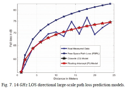
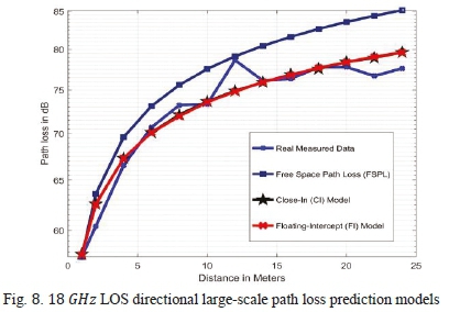
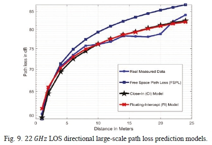
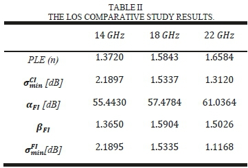
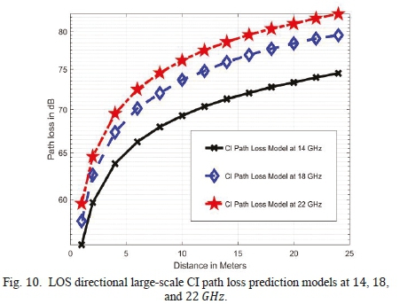
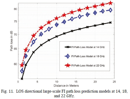
Figures 7, 8, and 9 show the CI and FI models with the real measured data and the FSPL curves at 14, 18, and 22 GHz, respectively. It is clear from these figures that both the CI and FI LOS path loss models fit the real measured data in all frequency bands used in this study (14, 18, and 22 GHz) and has comparable performance (the path loss curves for both CI and FI models are overlapped). For the CI model, the PLE values for the LOS scenario in this indoor corridor environment were 1.3720, 1.5843, and 1.6584 at 14, 18, and 22 GHz, respectively. It is worth noting that the PLE increased logarithmically and not linearly with the operating frequency. However, all these values are much lower than the value of the theoretical free space path loss exponent (FSPLE=2) as shown in Figures 7, 8, and 9. This is due to the richness of reflections, diffractions, and the waveguiding effects in this environment so that the multipath components at the receiver side will result in constructive interference. The values of the minimum standard deviation for the Gaussian random variable that represents the SF were between 2.1897 and 1.3120 dB at 14 and 22 GHz. It is clear that the standard deviation values decreasing with the frequency. For the FI model, the parameter values of a (floating-intercept) were 55.4430, 57.4784, and 61.0364 dB at 14, 18, and 22 GHz, respectively; and b (slope of the path loss curve) values were between 1.3650 and 1.5026, these values are approximately the same as the PLE values which make the same behavior in this environment. Moreover, it can be seen that the FI model provides the same standard deviation values as the CI model in the LOS scenario. Table II summarises the LOS parameters of the CI and FI path loss models at all frequencies. Figures 10 and 11 show the CI and FI path loss models curves at the frequency bands adopted in this work.
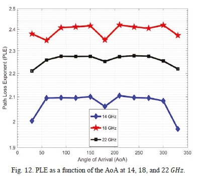
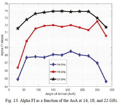
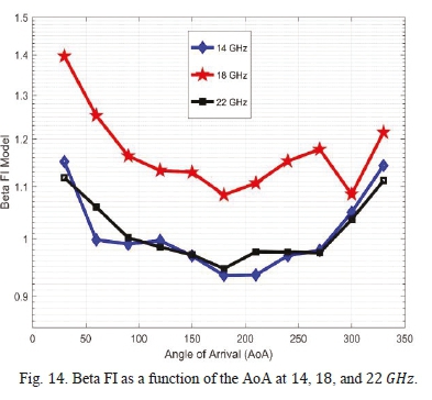
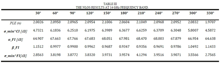
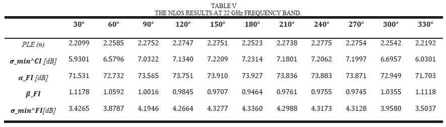
This section represents the NLOS performance study of the CI and FI path loss models in terms of the AoA. It is clear and known that NLOS communications have higher path loss values than the LOS. However, we need to see how the behavior of these path loss models when taking into account the AoA for enclosed environments such as corridors. The collected NLOS data is analyzed (using Excel and MATLAB) in order to calculate the parameters of the CI and FI models. The value of the AoA has increased by 30 (approximately 130 to 230% of the HPBW of the horn antennas used) at each Tx-Rx separation distance in the measurement campaigns. Fig. 12 represents the performance of the PLE as a function of the AoA at 14, 18, and 22 GHz bands. It is observed that the PLE exhibits symmetrical behavior around 180 AoA, which is due to the symmetric nature of these indoor corridor environments and the waveguiding effects. The PLE values change within a small band and have a better performance at 30 and 330 AoA (near the LOS path) and 180 AoA (total symmetrical reflection from the back wall and side walls). Also, it is worth knowing that when the antennas are aligned on boresight or 180 misalignment, the effect of the main lobe and back lobe results in the gain (path loss exponent reduction). Furthermore, it is notable that the 18 GHz band has the highest PLE values in the NLOS scenario, which means the reflections from the dry concrete and bricks become difficult at this band compared to the other frequency bands used (14 and 22 GHz). Figures 13 and 14 show the behavior of the parameters, a and βof the FI model, respectively. The values of a increased with the frequency since this coefficient represent the floating-intercept. It is observed that the performance of βis comparable to the performance of the PLE, and both have worst values at the 18 GHz band. Tables III, IV, and V summarize the performance of the CI and FI path loss models as a function of the AoA. It can be seen that the FI model provides lower values of the minimum standard deviation (from 1.8 to 2.9 dB) compared to the CI model in the NLOS scenario at all the selected frequency bands.
V. Conclusion
This paper presents results of measurement campaigns that have been carried out in an indoor corridor environment at 14, 18, and 22 GHz frequency bands. The measurements were performed using channel sounder based on Rohde and Schwarz SMF 100A for Radio Frequency Signal Generator as the transmitter, and Rohde and Schwarz FSIQ 40 Signal Analyzer as the receiver for all the frequency bands considered. Two path loss prediction models are presented, investigated, and compared for both the LOS and NLOS communication scenarios of this environment using two vertically polarized high-gain directional steerable antennas. The path loss models adopted in this work are the single-frequency CI model and the single-frequency FI model. The LOS performance study showed that both CI and FI models have very similar performance at all frequencies and fit the real measured data. The PLE of the CI model has a notable increase with the frequency since the LOS range of its value was 1.37 and 1.66 at 14 and 22 GHz, respectively. However, all the LOS values of the PLE were less than the value of the FSPLE. Moreover, the performance study considered an investigation of the behavior of the CI and FI models' parameters as a function of the AoA in the NLOS communication scenario.
The results showed that the parameters of the path loss models exhibit symmetrical behavior around 180° AoA; this is because of the symmetry of the environment used and the abundance of reflection, diffraction, and waveguiding effects in enclosed environments such as corridors. Also, it is clear that the models' parameters change within a small band and have a better performance at the AoA of 30° and 330° (near the LOS path) and 180° (total symmetrical reflection from the back wall and side walls). Besides, the MMSE technique was adopted to optimize the parameters of the path loss models. This technique fits the real measured data with the least error (by minimizing the value of the standard deviation σ). It was notable that the FI model provides the same standard deviation values as the CI model in the LOS scenario. On the other hand, the FI model provides a notable reduction (from 1.8 to 2.9 dß) compared to the CI model in the NLOS scenario at all frequency bands. Also, the LOS and NLOS results reveal that the CI and FI models can be trusted as good path loss models for corridor environments and exhibit stable behavior over distances and frequencies. Finally, it can be seen that because of the frequency jump from the cmWave to the mmWave regime, future millimeter-wave communications need to use higher gain antennas even in indoor environments to compensate for the extra path loss.
References
[1] N. O. Oyie and T. J. O. Afollo, "Measurements and analysis of large scale path loss model at 14 and 22 GHz in indoor corridor," IEEE Access, vol. 6, pp. 17205-17214, Feb. 2018. [ Links ]
[2] L. Pometcu and R. D'Errico, "An Indoor Channel Model for High Data-Rate Communications in D-Band," IEEE Access, vol. 8, pp. 9420-9433, Dec. 2019. [ Links ]
[3] A. Osseiran, J. F. Monserratand and P. Marsch, "5G mobile and wireless communications technology," Int. J. Satell. Commun. and Networ., vol. 34, no. 3, pp. 351-360, May. 2016. [ Links ]
[4] M. Aborahama et al., "Large-scale channel characterization at 28 GHz on a university campus in the United Arab Emirates," Telecommun. Sys., vol. 1, pp. 1 -15, Jan. 2020. [ Links ]
[5] F. Hossain et al., "Indoor millimeter-wave propagation prediction by measurement and ray tracing simulation at 38 GHz," Symmetry, vol. 10, p.464, Oct. 2018. [ Links ]
[6] X. Wu et al., "60-GHz millimeter-wave channel measurements and modeling for indoor office environments," IEEE Trans. Antennas Propag., vol. 65, pp. 1912-1924, Feb. 2017. [ Links ]
[7] T. Kleine-Ostmann et al., "Measurement of channel and propagation properties at 300 GHz" 2012 Conf. Precision electromagn. Measurements, Jul. 2012, pp. 258-259.
[8] G. R. MacCartney, H. Yan, S. Sun, and T. S. Rappaport, "A flexible wideband millimeter-wave channel sounder with local area and NLOS to LOS transition measurements," 2017 IEEE Int. Conf. Commun. (ICC), May. 2017, pp. 1-7.
[9] A. Zhou et al., "60 GHz channel measurements and ray tracing modeling in an indoor environment," 2017 9th Int. Con. Wireless Commun. Signal Proces. (WCSP), vol. 63, no. 9, pp. 3029-3056, May. 2015. [ Links ]
[10] P.F.M. Smulders, "Statistical characterization of 60-GHz indoor radio channels," IEEE Trans. Antennas Propag., vol. 57, no. 10, pp. 2820-2829, Oct. 2009. [ Links ]
[11] A. Al-Samman et al., "Millimeter-wave propagation measurements and models at 28 GHz and 38 GHz in a dining room for 5G wireless networks," Measurement, vol. 130, pp. 71-81, Dec. 2018. [ Links ]
[12] T. S. Rappaport, G. R. MacCartney, M. K. Samimi, and S. Sun, "Wideband millimeter-wave propagation measurements and channel models for future wireless communication system design," IEEE Trans. Commun., Oct. 2015, pp. 1-6.
[13] C. L. Cheng, S. Kim, and A. Zaji'c, "Comparison of path loss models for indoor 30 GHz, 140 GHz, and 300 GHz channels," 2017 11th European Conf. AntennasPropag. (EUCAP), Mar. 2017, pp. 716-720.
[14] T. S. Rappaport, S. Sun, M. Rimma, H. Zhao, and Y. Azar, K. Wang, G. N. Wong, J. K. Schulz, M. Samimi, and F. Gutierrez, "Millimeter wave mobile communications for 5G cellular: It will work!," IEEE Access, vol. 1, pp. 335349, May. 2013. [ Links ]
[15] G. Zhang, K. Saito, W. Fan, X. Cai, P. Hanpinitsak, J. I. Takada, and G. F. Pedersen, "Experimental characterization of millimeter-wave indoor propagation channels at 28 GHz," IEEE Access, vol. 6, pp. 76516-76526, Nov. 2018. [ Links ]
[16] Y. K. Yoon, and K. W. Kim, and Y. J. Chong, "Site Prediction Model for the over Rooftop Path in a Suburban Environment at Millimeter Wave," Int. J. Antennas Propag., vol. 2019, 2019. [ Links ]
[17] M. Marcus and B. Pattan, "Millimeter wave propagation: spectrum management implications," IEEE Microwave Magazine, vol. 6, no. 2, pp. 5462, Aug. 2005. [ Links ]
[18] G. R. MacCartney, and J. Zhang, S. Nie, and T. S. Rappaport, "Path loss models for 5G millimeter wave propagation channels in urban microcells," Globecom, pp. 3948-3953, Dec. 2013.
[19] N. O. Oyie and T. J. O. Afullo, "An Empirical Approach to Omnidirectional Path Loss and Line-of-sight Probability Models at 18 GHz for 5G Networks," 2018 Prog. Electromagn. Res. Symp. (PIERS-Toyama), Aug. 2018, pp. 129-136.
[20] N. O. Oyie and T. J. O. Afullo, "A Comparative Study of Dual-Slope Path Loss Model in Various Indoor Environments at 14 to 22 GHz," 2018 Prog. Electromagn. Res. Symp. (PIERS-Toyama), Aug. 2018, pp. 121 -128.
[21] Z. Pi and F. Khan, "An introduction to millimeter-wave mobile broadband systems," IEEE Commun. Mag., vol. 49, no. 6, pp. 101-107, Jun. 2011. [ Links ]
[22] T. S. Rappaport, Y. Xing, G. R. MacCartney, A. F. Molischand, E. Mellios, and J. Zhang, "Overview of millimeter wave communications for fifth-generation (5G) wireless networks-With a focus on propagation models," IEEE Trans. Antennas Propag., vol. 65, no. 12, pp. 6213-6230, Aug. 2017. [ Links ]
[23] J. Lota, S. Sun, and T. S. Rappaport, and A. Demosthenous, "5G uniform linear arrays with beamforming and spatial multiplexing at 28, 37, 64, and 71 GHz for outdoor urban communication: A two-level approach," IEEE Trans. Veh. Techno, vol. 66, no. 11, pp. 9972-9985, Aug. 2017. [ Links ]
[24] S. Y. Seidel and H. W. Arnold, "Propagation measurements at 28 GHz to investigate the performance of local multipoint distribution service (LMDS)," Proc. GLOBECOM'95, vol. 1, pp. 754-757, Nov. 1995. [ Links ]
[25] S. Kim, W. T. Khan, A. Zaji'c, and J. Papapolymerou, "D-band channel measurements and characterization for indoor applications," IEEE Trans. Antennas Propag., vol. 63, no. 7, pp. 3198-3207, Apr. 2015. [ Links ]
[26] O. T. Kleine, K. Pierz, G. Hein, P. Dawson, and M. Koch, "Audio signal transmission over THz communication channel using semiconductor modulator," Electron. Lett., vol. 40, no. 2, pp. 124-126, Feb. 2004. [ Links ]
[27] C. Jastrow, S. Priebe, B. Spitschan, J. Hartmann, M. Jacob, T. Kurner, T. Schrader, and O. T. Kleine, "Wireless digital data transmission at 300 GHz," Electron. Lett., vol. 46, no. 9, pp. 661 -663, Apr. 2010. [ Links ]
[28] S. Kim and A. G. Zaji'c," A path loss model for 300-GHz wireless channels," 2014 IEEE Antennas and Propag. Soc. Int. Sym. (APSURSI), Jul. 2014, pp. 1175-1176.
[29] R. Piesiewicz, O. T. Kleine, N. Krumbholz, D. Mittleman, M. Koch, J. Schoebei, and T. Kurner, "Short-range ultra-broadband terahertz communications: Concepts and perspectives," IEEE Antennas Propag. Mag., vol. 49, no. 6, pp. 24-39, Dec. 2007. [ Links ]
[30] R. Piesiewicz, C. Jansen, D. Mittleman, T. O. Kleineand, M. Koch, and T. Kurner, "Scattering analysis for the modeling of THz communication systems," IEEE Trans. Antennas Propag., vol. 55, no. 11, pp. 3002-3009, Nov. 2007. [ Links ]
[31] Y. Yang, M. Mandehgar, and D. R. Grischkowsky, "Broadband THz pulse transmission through the atmosphere," IEEE Trans. Tera Sci. Tech., vol. 1, no. 1, pp. 264-273, Aug. 2011. [ Links ]
[32] J. M. Jornet, I. F. Akyildiz, "Channel modeling and capacity analysis for electromagnetic wireless nanonetworks in the terahertz band," IEEE Trans. on Wireless Commun., vol. 10, no. 10, pp. 3211-3221, Aug. 2011. [ Links ]
[33] R. Piesiewicz, T. O. Kleine, N. Krumbholz, D. Mittleman, M. Koch, and T. Kurner, "Terahertz characterisation of building materials," Electron. Lett, vol. 41, no. 18, pp. 1002-1004, Sep. 2005. [ Links ]
[34] C. Jansen, R. Piesiewicz, D. Mittleman, T. Kurner, and M. Koch, "The impact of reflections from stratified building materials on the wave propagation in future indoor terahertz communication systems," IEEE Trans. Antennas Propag., vol. 56, no. 5, pp. 1413-1419, May. 2008. [ Links ]
[35] S. Priebe, M. Jacob, C. Jastrow, T. O. Kleine, T. Schrader, and T. Kurner, "A comparison of indoor channel measurements and ray tracing simulations at 300 GHz," 35th Int. Conf. Infra., Milli., Tera. Waves, Sep. 2010, pp. 1-2.
[36] M. Jacob, S. Priebe, R. Dickhoff, T. O. Kleine, T. Schrader, and T. Kurner, "Diffraction in mm and sub-mm wave indoor propagation channels," IEEE Trans. Micro. Theory Techni., vol. 60, no. 3, pp. 833-844, Jan. 2012. [ Links ]
[37] P. Smulders et al.,"Exploiting the 60 GHz band for local wireless multimedia access: prospects and future directions," IEEE Commun. Mag., vol. 40, no. 1, pp. 140-147, Aug. 2002. [ Links ]
[38] M. Fryziel, C. Loyez, L. Clavier, N. Rolland, P. A. Rolland, "Path-loss model of the 60-GHz indoor radio channel,"Micro. Opt. Techn. Lett., vol. 34, no. 3, pp. 158-162, Aug. 2002. [ Links ]
[39] H. Xu, V. Kukshya, and T. S. Rappaport, "Spatial and temporal characteristics of 60-GHz indoor channels," Micro. Opti. Tech. lett., vol. 20, no. 3, pp. 620-630, Aug. 2002. [ Links ]
[40] N. Moraitis, and P. Constantinou, "Indoor channel measurements and characterization at 60 GHz for wireless local area network applications," IEEE Trans. Antennas Propag, vol. 52, no. 12, pp. 3180-3189, Dec. 2004. [ Links ]
[41] T. Zwick, and T. J. Beukema, and H. Nam, "Wideband channel sounder with measurements and model for the 60 GHz indoor radio channel," IEEE Trans. Veh. Tech., vol. 54, no. 4, pp. 1266-1277, Aug. 2005. [ Links ]
[42] H. Yang et al., "Indoor channel measurements and analysis in the frequency bands 2 GHz and 60 GHz," 2005 IEEE 16th Int. Sym. Personal, Indoor Mobile Radio Commun., vol. 1, pp. 579-583, Sep. 2005. [ Links ]
[43] S. Geng, J. Kivinen, X. Zhao, and P. Vainikainen, "Millimeter-wave propagation channel characterization for short-range wireless communications," IEEE Trans. Veh. Tech., vol. 58, no. 1, pp. 3-13, May. 2008. [ Links ]
[44] Y. Azar, G. N. Wong, K. Wang, R. Mayzus, J. K. Schulz, H. Zhao, F. Gutierrez, D. Hwang, and T. S. Rappaport, "28 GHz propagation measurements for outdoor cellular communications using steerable beam antennas in New York City," 2013 IEEE Int. Conf. Commun. (ICC), Jun. 2013, pp. 5143-5147.
[45] S. Sun, G. R. MacCartney, M. K. Samimi, and T. S. Rappaport, "Synthesizing omnidirectional antenna patterns, received power and path loss from directional antennas for 5G millimeter-wave communications," 2015 IEEE Global Commun. Conf. (GLOBECOM), Dec. 2015, pp. 1-7.
[46] H. Zhou, "Phased array for millimeter-wave mobile handset," 2014 IEEE Antennas Propag. Soc. Int. Sym. (APSURSI), Jul. 2014, pp. 933-934.
[47] T. S. Rappaport, S. Sun, and M. Shafi, "5G channel model with improved accuracy and efficiency in mmWave bands," IEEE 5G Tech Focus, vol. 1, no. 1, pp. 1-6, Mar. 2017. [ Links ]
[48] S. Sun, G. R. MacCartney, and T. S. Rappaport, "Millimeter-wave distance-dependent large-scale propagation measurements and path loss models for outdoor and indoor 5G systems," 2016 10th European Conf. Ant. Propag. (EuCAP), Apr. 2016, pp. 1-5.
[49] H. K. Rath, and S. Timmadasari, B. Panigrahi, and A. Simha, "Realistic indoor path loss modeling for regular WiFi operations in India," 2017 Twenty-third Nat. Conf. Commun. (NCC), Mar. 2017, pp. 1-6.
[50] A. F. Molisch, A. Karttunen, R. Wang, and C. U. Bas, S. Hur, J. Park, and J. Zhang, "Millimeter-wave channels in urban environments," IEEE 5G Tech. Focus, Apr. 2016, pp. 1-5.
[51] K. Haneda, "Channel models and beamforming at millimeter-wave frequency bands," IEICE Trans. on Commun., vol. 98, no. 5, pp. 755-772, Mar. 2015. [ Links ]
[52] C. Phillips, D. Sicker, and D. Grunwald, "A survey of wireless path loss prediction and coverage mapping methods," IEEE Commun. Sur. Tut., vol. 15, no. 1, pp. 255-270, Mar. 2012. [ Links ]
[53] S. Sun et al., "Investigation of prediction accuracy, sensitivity, and parameter stability of large-scale propagation path loss models for 5G wireless communications," IEEE Trans. Veh. Tech., vol. 65, no. 5, pp. 2843-2860, Mar. 2016. [ Links ]
[54] A. I. Sulyman, A. Alwarafy, G. R. MacCartney, T. S. Rappaport, and A. Alsanie, "Directional radio propagation path loss models for millimeter-wave wireless networks in the 28-, 60-, and 73-GHz bands," IEEE Trans. Wireless Commun., vol. 15, no. 10, pp. 6939-6947, Jul. 2016. [ Links ]
[55] A. I. Sulyman, A. T. Nassar, M. K. Samimi, G. R. MacCartney, T. S. Rappaport, and A. Alsanie, "Radio propagation path loss models for 5G cellular networks in the 28 GHz and 38 GHz millimeter-wave bands," IEEE Commun. Mag., vol. 52, no. 9, pp. 78-86, Sep. 2014. [ Links ]
[56] S. Ju, and T. S. Rappaport, "Millimeter-wave extended NYUSIM channel model for spatial consistency," 2018 IEEE Global Commun. Conf. (GLOBECOM), Dec. 2018, pp. 1-6.
[57] G. R. Maccartney, T. S. Rappaport, M. K. Samimi, and S. Sun, "Millimeter-wave omnidirectional path loss data for small cell 5G channel modeling," IEEE Access, vol. 3, pp. 1573-1580, Aug. 2015. [ Links ]
[58] S. Rangan, T. S. Rappaport, and E. Erkip, "Millimeter wave cellular wireless networks: Potentials and challenges," Proc. IEEE 102.3, Feb. 2014, pp.366-385.
[59] J. Ryan, G. R. MacCartney, and T. S. Rappaport, "Indoor office wideband penetration loss measurements at 73 GHz," 2017 IEEE Int. Conf. Commun. Workshops (ICC Workshops), May. 2017, pp. 228-233.
[60] H. hao, R. Mayzus, S. Sun, M. Samimi, J. K. Schulz, Y. Azar, K. Wang, G. N. Wong, F. Gutierrez, and T. S Rappaport, "28 GHz millimeter wave cellular communication measurements for reflection and penetration loss in and around buildings in New York City," 2013 IEEE Int. Conf. Commun. (ICC), Jun. 2013, pp. 5163-5167.
[61] G. R. MacCartney, and T. S. Rappaport, "73 GHz millimeter wave propagation measurements for outdoor urban mobile and backhaul communications in New York City," IEEE Int. conf. Commun. (ICC), Jun. 2014, pp. 4862-4867.
[62] G. R. MacCartney, M. K. Samimi, and T. S. Rappaport, "Omnidirectional path loss models in New York City at 28 GHz and 73 GHz," 2014 IEEE 25th Annual Int. Sym. Personal, Indoor, Mobile Radio Commun. (PIMRC), Sep. 2014, pp. 227-231.
[63] M. K. Samimi and T. S. Rappaport, "Ultra-wideband statistical channel model for non line of sight millimeter-wave urban channels," 2014 IEEE Global Commun. Conf, Dec. 2014, pp. 3483-3489.
[64] T. S. Rappaport, F. Gutierrez, E. Ben-Dor, J. N. Murdock, Y. Qiao, and J. I. Tamir, "Broadband millimeter-wave propagation measurements and models using adaptive-beam antennas for outdoor urban cellular communications," IEEE Trans. Antennas Propag., vol. 61, no. 4, pp. 1850-1859, Dec. 2012. [ Links ]
[65] E. Ben-Dor, T. S. Rappaport, Y. Qiao, and S. J. Lauffenburger, "Millimeter-wave 60 GHz outdoor and vehicle AOA propagation measurements using a broadband channel sounder," 2011 IEEE Global Telecommun. Conf GLOBECOM2011, Dec. 2011, pp. 1-6.
[66] D. He, B. Ai, K. Guan, Z. Zhong, and B. Hui, J. Kim, H. Chung, and I. Kim, "Channel measurement, simulation, and analysis for high-speed railway communications in 5G millimeter-wave band," IEEE Trans. Intel. Transp. Systems, vol. 19, no. 10, pp. 3144-3158, Dec. 2017. [ Links ]
[67] A. M. Al-Samman, T. A. Rahman, M. H. Azmi, N. R. Zulkefly, and A. M. Mataria, "Path loss model for outdoor environment at 17 GHz mm-wave band," 2016 IEEE 12th Int. Colloquium Signal Proc. Appl. (CSPA), Mar. 2016, pp.179-182.
[68] S. Sun, T. A. Thomas, T. S. Rappaport, H. Nguyen, I. Z. Kovacs, and I. Rodriguez, "Path loss, shadow fading, and line-of-sight probability models for 5G urban macro-cellular scenarios," 2015 IEEE Globecom Workshops (GC Wkshps), Dec. 2015, pp. 1-7.
[69] F. Qamar, M. Siddiqui, S. Hassam, M. N. Hindia, K. Dimyati, T. A. Rahman, and M. S. Talip, "Propagation Channel Measurement at 38 GHz for 5G mm-wave communication Network," 2018 IEEE Student Conf. Res. Devel. (SCOReD), Nov. 2018, pp. 1 -6.
[70] G. R. Maccartney, T. S. Rappaport, S. Sun, and S. Deng, "Indoor office wideband millimeter-wave propagation measurements and channel models at 28 and 73 GHz for ultra-dense 5G wireless networks," IEEE Access, vol. 3, pp.2388-2424, Oct. 2015. [ Links ]
[71] A. M. Al-Samman, T. Abd Rahman, and M. H. Azmi, "Indoor corridor wideband radio propagation measurements and channel models for 5G millimeter wave wireless communications at 19 GHz, 28 GHz, and 38 GHz Bands," Wireless Commun. Mobile Comp., vol. 2018, 2018. [ Links ]
[72] J. Senic, C. Gentile, P. B. Papazian, K. A. Remley, and J. Choi, "Analysis of E-band path loss and propagation mechanisms in the indoor environment," IEEE Trans. Antennas Propag., vol. 65, no. 12, pp. 6562-6573, Jul. 2017. [ Links ]
[73] S. Deng, G. R. MacCartney, and T. S. Rappaport, "Indoor and outdoor 5G diffraction measurements and models at 10, 20, and 26 GHz," 2016 IEEE Global Commun. Conf. (GLOBECOM), Dec. 2016, pp. 1 -7.
[74] S. Y. Seidel, and T. S. Rappaport, "914 MHz path loss prediction models for indoor wireless communications in multifloored buildings," IEEE Trans. Antennas Propag., vol. 40, no. 2, pp. 207-217, Feb. 1992. [ Links ]
[75] M. K. Elmezughi, T. J. Afullo, and N. O. Oyie, "Investigating the Impact of Antenna Heights on Path Loss Models in an Indoor Corridor Environment," icABCD2020. Conf., IEEE, Sep. 2020, pp. 1-7.
[76] J. Meinil'a, P. Kyosti, T. lams'a, and L. Hentifa " WINNER II channel models," Radio Tech. Conc. for IMT-Advanced, pp. 39-92, 2009.
[77] T. S. Rappaport et al., "Wireless communications: principles and practice," vol. 2, Jan. 1996.
[78] A. M. Al-Samman, T. A. Rahman, M. H. Azmi, A. Sharaf, Y. Yamada, and A. Alhammadi, "Path loss model in indoor environment at 40 GHz for 5G wireless network," 2018 IEEE 14th Int. Coll. Signal Proc. Appl. (CSPA), Mar. 2018, pp. 7-12.

Mohamed K. Elmezughi was born in Tripoli, Libya, in 1995. He received a bachelor's degree in Electrical Engineering (First Class Hons.) from the University of Tripoli, Libya, in 2017. He received a master's degree in Electronic Engineering (Cum Laude) from the University of KwaZulu-Natal (UKZN), Durban, South Africa, in 2020. Currently, he is working n the Ph.D. degree at the UKZN under the supervision of Prof. homas J. Afullo and co-supervision of Dr. Nicholas O. Oyie. he focus of his MSc research is on Millimeter Wave channel odeling for 5G mobile communication systems. The main ireas of his research interests are on Millimeter-Wave systems, ireless channel modeling, signal detection, antennas design, adio propagation, and channel parameters estimation.

Thomas J. Afullo (Student M'82-M'83-M'14-SM'18) received the B.Sc. (Hon.) in Electrical Engineering from the University of Nairobi, Kenya (1979); the MSEE on a Fulbright-Hays Scholarship from West Virginia University, Morgantown, USA (1983); and the Bijzondre License in Technology and the Ph.D. degree in Telecommunication Engineering from the Vrije Universiteit Brussel (VUB), Belgium (1989). From 1979 to 1986, he rose from rank of Pupil (Trainee) Engineer to Senior Executive Engineer in charge of transmission and radio planning with Kenya Posts and Telecommunication Corporation. From 1987 to 1994, he rose from the rank of Tutorial Fellow to Senior Lecturer and Head of Department of Electrical & Communications Engineering at Moi University, Eldoret, Kenya. From 1996 to 2002, he was Lecturer in Telecommunication at the Department of Electrical Engineering at the University of Botswana Gaborone. He joined the University of Durban-Westville as Associate Professor of Electrical Engineering in 2003. Since 2012, he has been Professor of Telecommunications Engineering in Discipline of Electrical, Electronic and Computer Engineering, University of KwaZulu-Natal (UKZN), Durban. He is also the Director of the Telkom Centre for Radio Access & Rural Technologies (CRART). He is a registered engineer with the Engineering Council of South Africa (ECSA), Fellow of the South African Institute of Electrical Engineering (SAIEE), and a rated researcher with the South African National Research Foundation (NRF). He was a member of Eta-Kappa Nu (Beta-Rho Chapter) in 1982, then became a faculty advisor and member of IEEE-Eta-Kappa Nu (Mu Eta Chapter) from 2016. He has spent Sabbatical Leave with Prof. Emilio Matriciani and Prof. Carlo Riva at Politechnico di Milano (POLIMI), in 2017; with Prof. Rajarathnam Chandramouli at Stevens Institute of Technology, New Jersey, also in 2017; and at the Department of Electronics, University of Kaiserslautern, Germany, in 1996, on a DAAD Fellowship. He has successfully supervised 16 Ph.D. and 27 Masters Students, as well as co-supervised 2 Ph.D. students. His research interests are in the area of Microwave and Millimeter-wave Propagation, Power Line Communications (PLC), and Free Space Optics (FSO).

Nicholas O. Oyie received the B.Tech. degree (First Class Hons.) in electrical and communication engineering from the Masinde Muliro University of Science and Technology, Kenya, in 2009, and the M.Sc. in telecommunication engineering from the Jomo Kenyatta University of Agriculture and Technology, Kenya, in 2016, and the PhD. degree in electronic engineering from the University of KwaZulu-Natal, Durban, South Africa, in 2019. He was with Essar Telecom, Kenya, as a Telecommunication Engineer from 2009 to 2010. His research areas of interest include radio wave propagation, radio resource and mobility management in wireless networks, femtocells, and quality of service support.

