


Services on Demand
Article
 English (pdf)
 Article in xml format
 Article references
Indicators

Related links
-
 Cited by Google
 -
 Similars in Google
Share

 Permalink
SAIEE Africa Research Journal
On-line version ISSN 1991-1696
Print version ISSN 0038-2221
SAIEE ARJ vol.111 n.2 Observatory, Johannesburg Jun. 2020
ARTICLES
Selection and Rating of the Step-up Transformer for Renewable Energy Application
Bonginkosi A. ThangoI; Jacobus A. JordaanII; Agha F. NnachiIII
IShwane University of Technology, South Africa (e-mail: thangotech@.gmail.com)
IIDept. of Electrical Engineering. Tshwane University of Technology. South Africa, (e-mail: (JordaanJA@tut.ac.za)
IIIMember, IEEE; Dept. of Electrical Engineering. Tshwane University of Technology. South Africa, (e-mail: NnachiAF@tut.ac.za)
ABSTRACT
In the past decade, South Africa has acquired more renewable energy (RE) generation capacity than the rest of the Sub-Saharan countries. This development has led to increasing concerns about problems associated with electrical equipment connected with the RE technologies, especially in wind and solar. These RE technologies have intermittent generation profiles and are connected to non-linear loads. The fundamental electrical equipment including the step-up transformer, with respect to which, high harmonic losses, abnormal temperature rise and gassing problems have been extensively reported within the last 10 years and remains a precedence for many Independent Power Producers (IPPs). A requirement of the step-up transformer is that IPPs are required to provide a technical schedule clarifying the harmonic and distortion content at the plant's point of common coupling (PCC). A lack of this knowledge to the transformer manufactures thereof leads to under-designing or over-designing cases if the harmonic content has been underestimated or overestimated respectively.
In hindsight, it may be beneficial for the Independent Power Producers and transformer manufactures to collaborate to assure the transformer design philosophy for the intended RE application is aligned with the technical requirements. In this paper, a method of de-rating the transformer when supplying non-sinusoidal loads is presented. In this method, the continuous power rating of the transformer is reduced to treat the additional losses as a result of harmonic penetration. Initially, a harmonic spectrum supplied by the IPP is used to calculate the transformer load and service losses. Secondly, the harmonic load spectrum is employed to compute de-rating factors ascribed to as "K-Factor" and "Factor-K", indicating the amount of de-rating necessary for the transformer under study when serving the considered harmonic spectrum. Lastly, the thermal considerations under the harmonic spectrum are presented.
Index Terms: Step-up transformer, Harmonic and distortion, Harmonic losses, Abnormal Temperature rise, Gassing, De-rating, Thermal requirements.
I. INTRODUCTION
In the last decade, the South African renewable energy programme (REIPPP) has attained international acknowledgement for its great success. The programme has been highly expedient to the country in terms of alleviating load shedding, diversifying the energy mix and modernization of clean energy generation. Renewable energy (RE) generation is a high priority in the agendum of most global governments. Based on the origin of respective RE sources, as well as social and economic precedence, to the greatest extent, they pursue an energy sphere that will be entrusted with economic development within the obligation to sustain the environment.
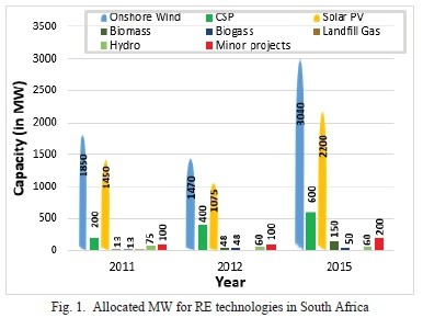
In 2011, the South African minister of energy provided a clear roadmap for the megawatt (MW) capacity that will be allocated to the various RE technologies by 2015 [1], [2] and [3]. As shown in Fig. 1, in 2012, the minister allocated a total of 3200 MW additional RE capacity following the initial success of 3725MW in 2011. By the year 2015, an additional increase of 6300 MW was allocated.
With the growth in the deployment of RE generation technologies, a valuable lesson has been the necessity to tailor the design of electrical equipment with RE technology-specific operating conditions. For instance, when transformer manufacturers design transformers intended to operate in RE applications, it is necessary to seek to address the amount of harmonics that will be seen by the transformer while in service. The presence of non-linear loads connected to the renewable technologies, especially wind and solar, draw distorted currents despite the fact that they are supplied with a sinusoidal voltage, is widespread and is progressing with the growth of the RE market. In solar photovoltaic (PV) transformers, these distorted currents ensue additional losses, dominantly in the winding conductors due to the impinging and deformed electromagnetic fields. Additional losses signify heat dissipation in the winding conductors such that the permissible thermal requirements are exceeded, culminating in the degradation of cellulose and liquid insulation and a possible risk of reducing the transformer service life.
Due to that, it is essential to minimize the continuous power load rating of the solar PV transformer, a procedure ascribed to as de-rating. The latter can be attained by the current harmonic spectrum of the non-linear loads in order to foretell and gain knowledge about the additional amount of transformer harmonic losses. Parameters known as the load's "K-factor" and 'Factor K", according to [4], [5] and [6], can then be employed to yield the quantity of de-rating necessary for the solar PV transformer.
Several authors have proposed various methods for de-rating the transformer rating when supplying non-linear loads [7], [8], [9], [10], [11] and [12]. In [13], Gouda et al presented a simulation model to study the effect of harmonics on a 25MVA oil-filled transformer using the MATLAB's Simulink. This study considers the impact of harmonic filters when the transformer is supplying pumping loads. In comparison to the measured K-factor, the simulated K-factor yield an error of about 5.3%. In [14], Meshram and Umredkar also presented a MATLAB simulation model of a 50KVA single phase transformer to study the impact of harmonics. Under the supplied harmonic profile, the de-rated power rating yields a percentage error of about 21%. In [15], a shift in the direction of Finite Element Method (FEM) is witnessed; Sharifian et al estimated the losses of a 50kVA transformer at fundamental and harmonic condition. In this study, the corresponding power rating of the transformer is calculated based on the harmonic loss factor and comparing the FEM method with an analytical approach. The results comparison yields an error of about 1.8%. There are no available studies in the literature that explores the operating of transformers with the renewable energy application. More research is needed to examine the selection of and rating of transformers within the renewable energy application.
In this paper, a method of de-rating the transformer when supplying non-sinusoidal loads is presented. In this method, the continuous power rating of the transformer is reduced to treat the additional losses as a result of harmonic penetration. More focus is drawn on a 5000kVA transformer intended to operate within a solar PV plant. The subsequent sections in this paper are structured as follows: Transformer losses, selection and rating of a transformer. Case study, harmonic losses, transformer de-rating and thermal requirements, as well as ending with a conclusion.
II. TRANSFORMER LOSSES
The load losses in solar PV transformers are generated by the current flow in the winding conductors. The load losses are comprised of the below-mentioned main loss components.
A. Load Loss
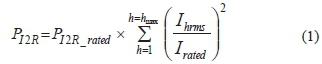
The copper loss or I2R loss is generated when the load current flows through the resistance of the winding conductors and busbars. This loss increase with the square of the harmonic current (1) and is calculated as shown in eq. (1) [16] and [17]. The root mean square (RMS) fundamental current under rated conditions is denoted by (1).
B. Winding Eddy loss
Winding eddy loss is induced by the leakage field imposing upon the surface of the winding conductors. When the transformer is supplying non-sinusoidal loads, the generated eddy loss is computed using eq. (2) [16] and [17].
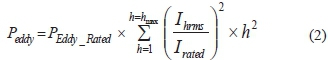
Here, and represent the winding Eddy loss of the transformer during service life and the Winding Eddy loss as measured current measured at fundamental frequency respectively.
C. Other stray loss
Other stray loss, a leakage field impinging upon the surface of the core, tank walls, and other steel structural parts exists. In the presence of harmonics, this loss are computed using eq. (3) [16] and [17].
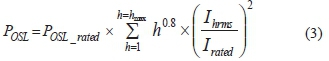
Here, P0SLand P0SL_RATED represent the other stray loss in in tank walls, core clamps, flitch plates, bus- bars etc. during the transformer service life and the other stray loss under rated conditions.
D. Temperature rise
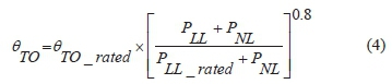
Temperature rise is generated by the heat produced when the winding conductors and steel structural parts undergo increased losses due to the distorted harmonic currents. The computation of the hotspot temperature in oil-immersed transformers, for self-cooled ONAN mode, the top-oil temperature (oto) as expressed as follows in eq. 4. Here, the top oil-temperature is progressive with the service losses to the power of 0.8 and may be evaluated for the harmonic conditions, founded on the rated load losses (Pll Rated) [18]. Here, the no-load and load losses under harmonic conditions are expressed as (Pnl) and (Pll).
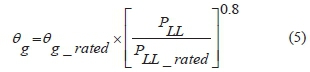
The hottest spot on the winding conductors rise over the top-oil temperature (0g) and is also progressive with the load losses to the power 0.8 and may be expressed as follows in eq. (5).
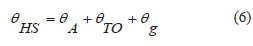
The hottest winding conductor temperature rise (ohs) over the ambient temperature (oa) is expressed as follows in eq. (6).
III. SELECTION AND RATING OF A TRANSFORMER
There are two methods commonly employed by manufacturers to take into consideration the additional losses when determining the suitable transformer intended to serve a harmonic spectrum. In [4], [5] and [6], the national electrical code presented the K-factor method to compute the factor in which the eddy losses have increased and designate a transformer that is capable to operate under a specific harmonic condition. This method is ascribed to as the K-factor and is calculated at the hth harmonic order and current (Ihrms) as shown in eq. (7).
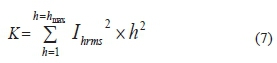
Based on eq. (7), once the K-factor for the harmonic load is acquired, it is easy to clearly describe a transformer with the closest K-rating conforming to standardized ranges of 4, 9, 13. 20, 30, 40, and 50 [4], [5] and [6]. In the case of a linear load which draws sinusoidal current, then the K-factor will be at unity. A high value of the K-factor signifies that the winding eddy losses in the transformer will be a multiple of the K value at the rated frequency. For transformers de-rated using the K-factor method, manufacturers are always challenged to design the transformer to have minimum eddy current losses at the rated frequency.
In another approach described in [6], a parameter described as the "factor K" is employed to assess what is the amount a regular transformer should be de-rated in order that the sum of the harmonic load losses does not exceed the rated design losses. This factor is computed as shown in eq. (8). The exponent "e" denotes the ratio of eddy current loss to I2R loss at rated frequency and the exponential "q" represent the nature of the winding design.
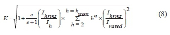
In practice, the value of "q" is generally approximated as 1.7 and 0.5 for transformers with round or rectangular cross-section conductor design and foil type winding design respectively.
IV. CASE STUDY
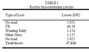
An oil-immersed solar PV transformer rated 5000kVA, was designed for a specific harmonic spectrum. The computed rated losses are presented in TABLE I.
A harmonic spectrum supplied by an Independent Power Producer (IPP) to the manufacturer is shown in Fig. 2. The transformer will be designed such that this harmonic spectrum is incorporated in the design philosophy.
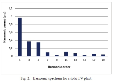
The supplied harmonic spectrum suggest that the solar PV transformer will undergo odd harmonics from the 3rd to the 19th order. This indicate the cooperative effort required between the transformer manufacturers and the IPP's. In the next section results of the transformer losses under the specified harmonic spectrum will be presented. Consequently, the required de-rating will be applied using the K-factor and Factor-K procedures.
V. HARMONIC LOSSES
In this section, the harmonic spectrum presented in the previous section is utilized in the computation of the anticipated transformer losses during its service life. The load losses and corrected losses under the supplied harmonic spectrum are tabulated in TABLE II.
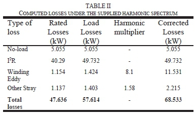
The transformer under study experienced an overall increase of 19% in the corrected losses. This foretells a considerably high amount of loss components contained by the harmonic spectrum. In practice, the transformer will experience the corrected losses when operating at full load. It is also evident that these losses will have an impact on the values of the de-rating factor and the transformer design. Moreover, the load losses also give the impression that transformers operating nearby will also be influenced despite the fact that the transformer under study will be the most impacted. The latter will also likely influence the grid supply. In the case of the transformer connected directly to this harmonic source, the observed losses will influence the cooling system. In studies conducted by Martin et al [16], Gray [17], Eeckhoudt et al [18] and Nyandeni et al [19] and [20] the resultant hotspot temperature rises due to the corrected losses lead to bubble formation and stray gassing, which significantly reduce the estimated transformer service life.
VI. TRANSFORMER DE-RATING
The design of the K-factor for the supplied harmonic spectrum on a per unit basis is shown in TABLE III. The corrected losses in the last section indicated a high loss content, which results from the high K-factor value. Initially, under the harmonic spectrum, the RMS value of the total harmonic current is computed, 1.111 in this case. Afterward the squares of the harmonic loss factors of each harmonic current is computed, leading to the estimation of a suitable value of K. In the harmonic spectrum presented in Fig. 2, a K-rating of 9 would be appropriate for this transformer.

In the case of designing the Factor-K as presented in TABLE IV the ratio of the winding eddy losses to the I2R losses is provided by the manufacturer to attain the value of e. Under other circumstances, this value will generally lie between the ranges of 0.05 to 0.1. The parameter "q" is dependent on the transformer design and should lie between the ranges 1.5 to 1.7. With the load current of 131.22, the maximum permissible per-unit, non-sinusoidal load current is 118.108.
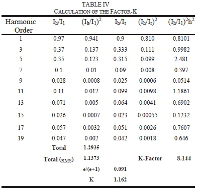
Based on the findings above, in practice, the transformer would need to be de-rated to 86.05% of nominal power rating when supplying the studied harmonic spectrum. In the next section, the thermal requirement for this transformer under the harmonic study is inspected.
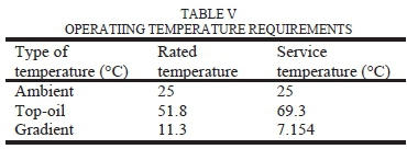
VII. TEMPERATURE RISE
The thermal capacity of a transformer is governed by parameters such as the loading profile, ambient temperature, cooling system and winding design. This capacity is determined by considering the maximum permissible thermal stresses of the insulating materials and calculations including the worse-case scenario of the loading profile and the ambient temperature. In TABLE V, the thermal capacity of the studied transformer under the considered harmonic spectrum is presented. An ambient temperature of 25°C is considered, and the winding mean-oil temperature of 53°C is calculated. The resultant hotspot temperature under these thermal parameters and the corrected losses is 101.45 °C.
The most critical aftermath of high hotspot temperature value is accelerated ageing of the cellulose and liquid insulation. The ageing process is a chemical action, where the hotspot temperature function as a catalyst.
VIII. Conclusion
This work underscores the significance of the collaboration between the IPP's and transformer manufactures to assure that the amount of harmonics and distortion present in RE generation plant is incorporated in the design philosophy. The calculation results presented in this work further show that harmonics and distortion cause excessive losses and hotspot temperature rise; indicating the individual transformer connected to the harmonic source is sensitive to the harmonic spectrum. Especially a significant increase on the winding eddy losses was observed. Further, the results indicate that for regular transformers intended to serve non-sinusoidal loads, they must be de-rated in a way that is suitable to their design. Future work will include conducting harmonic studies of a solar PV plant's components using simulation software like DigSILENT to obtain the actual harmonic spectrum at the point of common coupling.
In any case, prior to the deployment and operation of RE energy technologies, a closer collaboration and alignment is imperative between the IPP's and manufacturers to guide the design philosophy of electrical equipment such that they are capable of withstanding the intended operating conditions.
References
[1] Department of Energy, "Ministerial Determination", No. 36005, 1 August 2011. [Online]. Available: http://www.energy.eov.za
[2] Department of Energy, "Government Gazette", No. 36005, 19 December 2011. [Online],Available: https://sawea.ore.za
[3] Department of Energy, "Government Gazette", No. 39111, 18 August 2015. [Online]. Available: http://www.energy.gov.za
[4] M.W Earley and r.H Murray et al, "National Fire Protection Code Handbook, 6th ed., 1992. [Online]. Available: https://www.amazon.com
[5] B.J McPartland, "Quizzes on the code, definitions-article 100", National electric code, vol. 89, 1990. [Online]. Available: https://nationaltradesman.com
[6] NFPA 70 National Electrical Code, "National fire protection", National electric code, 1993. [Online]. Available: https://www.nfpa.org
[7] G. W. Massey, "Estimation methods for power system harmonic effects on power distribution transformers," in IEEE Transactions on Industry Applications, vol. 30, no. 2, pp. 485-489, March-April 1994. [ Links ]
[8] L. W. Pierce, "Transformer design and application considerations for nonsinusoidal load currents," in IEEE Transactions on Industry Applications, vol. 32, no. 3, pp. 633-645, May-June 1996. [ Links ]
[9] M. T. Bishop, J. F. Baranowski, D. Heath and S. J. Benna, "Evaluating harmonic-induced transformer heating," in IEEE Transactions on Power Delivery, vol. 11, no. 1, pp. 305-311, Jan. 1996. [ Links ]
[10] M. D. Hwang, W. M. Grady and H. W. Sanders, "Calculation of winding temperatures in distribution transformers subjected to harmonic currents," in IEEE Transactions on Power Delivery, vol. 3, no. 3, pp. 1074-1079, July 1988. [ Links ]
[11] K. Hameyer, R. Belmans," Numerical modelling on design of electric machines and devices". WIT Press May, 1999.
[12] J. Driesen, r. Belmans and K. Hameyer, "Finite element modelling of thermal contact resistances and insulation layers in electrical machines," IEEE International Electric Machines and Drives Conference. IEMDC'99. Proceedings (Cat. No.99EX272), Seattle, WA, USA, 1999, pp. 222-224.
[13] O. E. Gouda, G. M. Amer, W. A. A. Salem, "A Study of K-Factor Power Transformer Characteristics by Modeling Simulation", Engineering, Technology & Applied Science Research Vol. 1, 2011 [ Links ]
[14] V. L. Meshram, S. V. Umredkar, "Distribution Transformer Due to Nonlinear Loads", International Journal of Engineering Research and Applications, April 2014.
[15] M. B. B. Sharifian, J. Faiz, S. A. Fakheri and A. Zraatparvar, "Derating of distribution transformers for non-sinusoidal load currents using finite element method," Hf1 IEEE International Conference on Electronics, Circuits and Systems, 2003. ICECS 2003. Proceedings of the 2003, Sharjah, 2003, pp. 754-757 Vol.2.
[16] D. Martin, D. Martin, N. Lelekakis, J. Wijaya, M. Duval and T. Saha, "Investigations Into the Stray Gassing of Oils in the Fault Diagnosis of Transformers," in IEEE Transactions on Power Delivery, vol. 29, no. 5, pp. 2369-2374, Oct. 2014. [ Links ]
[17] I.A.r. Gray, "Practical Experience Gained from Dissolved Gas Analysis at an Aluminium Smelter", Doble Eskom Annual International Conference Southern Africa, 2010.
[18] S. Eeckhoudt, S. Autru and L. Lerat, "Stray gassing of transformer insulating oils: impact of materials, oxygen content, additives, incubation time and temperature, and its relationship to oxidation stability," in IEEE Electrical Insulation Magazine, vol. 33, no. 6, pp. 27-32, November-December 2017. [ Links ]
[19] D.B Nyandeni, M. Phoshoko, r. Murray, B.A Thango," Transformer Oil Degradation on PV Plants - A Case Study", 8th South African Regional Conference (CIGRE), 14-17 November, 2017.
[20] B.A. Thango, D.B. Nyandeni, P.M. Molepo, J.A Jordaan, A.F. Nnachi, "Solar Power Plant Transformer Loss Computation under Harmonic Currents using Finite Element Method", 9th CIGRE Southern Africa Regional Conference, 1st - 4th October 2019, Johannesburg, South Africa.

Bonginkosi A. Thango obtained his Bachelor of Technology (B.Tech.) in Electrical Engineering in 2017 at the Tshwane University of Technology, South Africa. In 2019, he was awarded Cum Laude for Master of Engineering (M.Eng.) in the same University. He is currently pursuing his Doctor of Engineering (D.Eng.) degree with the same University. His research interest includes Finite Element Method modelling, condition monitoring of transformers. Renewable Energy, Data Analysis and Mathematical modelling.

Jacobus A. Jordaan obtained his Bachelor's degree in Electrical/Electronic Engineering (B.Eng) in 1997 from the North-west University, South Africa, and his M.Eng degree in 2002 from the same university. He then obtained a double master's degree in Electronic Engineering and Engineering Management in 2004 from the South Westphalia University of Applied Sciences (SOEST), Germany and University of Bolton. In 2007 He obtained a doctorate degree in Electrical Engineering at the Tshwane University of Technology, South Africa. He is currently an associate professor at the same university, with his interests and field of research including micro-controllers, programming, signal processing and mathematical modelling.

Agha F. Nnachi obtained his Bachelor degree (B.Eng.) in electrical engineering in 2002 at Nnamdi Azikiwe University Awka. Nigeria. In 2009/2010, he received double master's degree MTech and MSc in electrical engineering at Tshwane University of Technology. In 2015, he obtained government certificate of competency (GCC) in electrical engineering. In 2017, he received Doctorate degree in electrical engineering at Tshwane University of Technology. He is a registered professional engineer with Engineering Council of South Africa and a senior member of the South African Institute of Electrical Engineers. His research interest includes power electronic converters, high voltage DC, renewable energy and power quality.
This work was supported in part by the Tshwane University of Technology.

