


Services on Demand
Article
 English (pdf)
 Article in xml format
 Article references
Indicators

Related links
-
 Cited by Google
 -
 Similars in Google
Share

 Permalink
SAIEE Africa Research Journal
On-line version ISSN 1991-1696
Print version ISSN 0038-2221
SAIEE ARJ vol.111 n.1 Observatory, Johannesburg Mar. 2020
ARTICLES
Pedestal Substrate Integrated Waveguide filter with both electric and magnetic cross-couplings
Leanne JohnsonI; Prof. Petrie MeyerII; Dr. Elmine MeyerIII
IMember, IEEE Review October 2019. Leanne Johnson is at the Electrical and Electronic Department at Stellenbosch University. (e-mail: 17698413@sun.ac.za)
IIMember, IEEE Prof. Petrie Meyer is at the Electrical and Electronic Department at Stellenbosch University. (e-mail: pmeyer@sun.ac.za)
IIIMember, IEEE Dr. Elmine Meyer is at Eindhoven University of Technology (e.meyer@tue.nl)
ABSTRACT
In this paper, the recently proposed Pedestal Substrate Integrated Waveguide (SIW) structure, consisting of evanescent-mode SIW cavities, loaded with pedestal-shaped metal inserts, is utilized to design a coupled resonator filter with both positive and negative cross-coupling. It is shown that both types of coupling, for a large range of coupling values for both, can very simply be implemented in this structure, with electric coupling obtained by means of an I-shaped strip_line between pedestal tops, and magnetic coupling obtained using inductive irises. The proposed structure can also introduce mixed coupling. Graphs are presented to show the range of coupling values attainable. A proof-of-concept sixth order cross-coupled bandpass filter, with a 5 % bandwidth at 5 GHz, and both real and imaginary axis transmission zeros, are designed and measured.
Index Terms: Electric coupling, magnetic coupling, mixed coupling, substrate integrated waveguide, cross coupling, pedestal resonator.
I. Introduction
M icrowave filters are fundamental parts of wireless communication systems. Modern systems in particular demand low cost filters with good frequency selectivity, wide stopbands and compact size. For many applications, coupled resonator (CR) filters are very well suited, offering low-loss, narrow bandwidths and small footprints.
One of the big advantages of CR-filters is the ability to create cross-coupling between non-adjacent resonators, in order to introduce transmission zeros for increased selectivity, and/or equalization of group delay [1] - [4]. Cross-coupling can be either predominantly inductive (magnetic, normally denoted as positive), capacitive (electric, normally denoted as negative), or a combination of inductive and capacitive (denoted as mixed). Cross-coupled and source-load coupled filters are most often implemented in cavity filters [1], [5], [6], with positive coupling the pre-eminent scheme, as this can be implemented by simple apertures. Negative coupling is often more difficult to implement, commonly requiring additional components. In planar technology on the other hand, negative coupling is very common, and easily realised through the capacitive coupling between lines. To implement both types of cross-coupling in a single filter in any of these classical structures can be problematic, yet this is quite often required when improvements in both stop-band attenuation and group delay are necessary. Substrate Integrated Waveguide (SIW) structures, developed over the past two decades, currently offer some of the best possibilities to achieve filters with all three forms of coupling. These filters can be viewed as dielectric-filled waveguide filters, with a natural coupling mechanism in the form of inductive aperture coupling, i.e. positive coupling. However, due to the planar, etched construction, and the support created by the dielectric, negative couplings can also be easily implemented. One popular approach in SIW technology is to fold a filter in the vertical direction and etch slots or coupling windows at specific locations in the separating ground plane to couple the electric field [7], [8]. Good examples are the fourth-order multilayer partial H-plane folded SIW filter with evanescent SIW sections at 10 GHz, proposed in [9], and the 13 GHz multi-layer filter in [8], which is aimed at suppressing the higher order modes of SIW bandpass filters with the implementation of magnetic, electric and mixed coupling. Coupling has also been realised by using planar lines. An example is [1], where four in-line SIW cavities are coupled magnetically with conventional irises, while the first and fourth cavities are electrically coupled with a microstrip transmission line inverter.
Coupling strips or probes or strips, as in [2] and [10] respectively, are also commonly used to achieve coupling. In [2], a third-order inline coaxial filter with both electrical and magnetic mixed coupling is presented, with electric coupling achieved by inserting a microstrip line between the coupling irises that connects the metallic caps at the open-end of both inner rods, and magnetic coupling is achieved with a coupling pin that connects to the inner rods of each coaxial resonator through a metallic gap.
Different types of coupling have also been used in comb line SIW structures [6]. Here, the coupling structure consists of an open-ended coplanar transmission line between comb line SIW resonators, with magnetic coupling realised by metallic posts, and electric coupling by a metallic disk with an airgap between the disk and the top metal layer. A similar design is introduced in [11] to produce mixed coupling. This design consists of classical iris-based coupling with a grounded coplanar line etched at the top of the resonators. A slightly different approach is presented in [12], where a fourth-order cross-coupled elliptic-filter with mixed coupling is proposed. The filter consists of two layers with an embedded strip line in combination with a conventional inductive iris to create both magnetic and electric coupling. Finally, in [13], an inter-resonator coupling structure implemented in SIW with mixed coupling is presented. Positive coupling is realised with conventional inductive irises, while the negative coupling is realised with a shorted microstrip line.
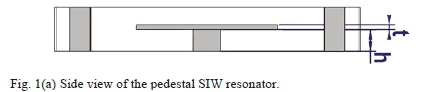
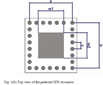
In most of the cases discussed, cross-couplings are limited in range, require lines on top of (i.e. outside of) the structure, or require the use of multi-layered SIW. This paper proposes an alternative, easily manufacturable, approach to realize all types of cross-coupling in an SIW structure, including electric, magnetic and mixed couplings in the same filter. The design utilizes the recently proposed pedestal SIW structure [14], consisting of evanescent-mode SIW cavities, loaded with pedestal-shaped metal inserts which are realised within the normal PC-board process, by a combination of flat resonators and vias. SIW pedestal filters utilize the mode separation characteristics of T-ridge SIW guides and were shown to provide flexibility in terms of input coupling and cross-coupling, as well as offering a user-selectable compromise between size, Q-factor and mode separation. A side and top view of a typical pedestal SIW resonator are shown in Figs. 1(a) and 1(b).
Using these resonators, positive couplings can be realised simply by apertures between the cavities, while negative couplings can be realised by etched lines on the same plane as the tops of the pedestals. Mixed couplings are obtained by combining the two mechanisms. The whole structure is simple to manufacture using only standard PC-board techniques, is closed (i.e. with no coupling lines not enclosed within the SIW structure) and offers a wide range of coupling values. In [14], the principle of the resonator is discussed in detail, and two simple filters are presented. Little attention is however given to the coupling aspects, especially the implementations and the ranges of coupling values. These aspects form the core of this paper. For illustration, a sixth order filter with transmission zeros for improved selectivity, as well as group delay equalization, is presented with a bandwidth of 5% at 5 GHz. The combination of transmission zeros is chosen to require both types of coupling, and a range of coupling values.
II. Filter Design
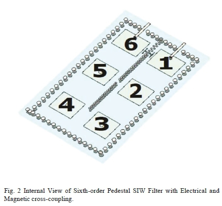
In coupled-resonator filters, cross-coupling can be used effectively to create transmission zeros at real frequencies to improve selectivity, or at imaginary frequencies to equalize group delay and reduce phase distortion. When transmission zeros at both real and imaginary frequencies are used in one filter design, both positive and negative cross-couplings are required, in addition to inline couplings of typically one sign throughout. To illustrate how well the pedestal structure lends itself to implementing all types of cross-coupling in a single filter, a sixth-order bandpass filter in the WiFi-band, with a center frequency of 5 GHz and a bandwidth of 5%, is chosen as the prototype. Using a sixth order normalized low-pass response, one transmission zero pair is added at a real frequency to improve the selectivity, and another pair at an imaginary frequency to optimize the phase response. The filter is implemented as six pedestal resonators in a folded configuration, as shown in Fig. 2.
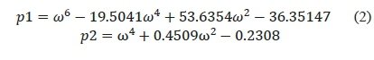
Classical synthesis procedures are used to derive a coupling matrix for the pedestal filter [15]. Starting with a 6-th order 20 dB return loss Chebychev low-pass response, with transmission zeros at ± j1.81, ± 1.15, 0 and ∞, the transfer function is
With
With input and output impedance values set to 1.0049 Ω, the resulting normalized coupling matrix is then calculated as
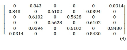
showing all positive inline couplings, and both positive and negative cross-couplings.
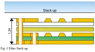
The filter is implemented in a stack-up of two Mercurywave cores (εrr = 3.5, thickness = 0.508 mm), bonded by a single layer of Mercurywave 1080 prepreg (εr8r = 3.5, thickness = 0.076 mm). As shown in Fig. 3, the top copper layer of the bottom core is used for the pedestal top, with blind vias forming the pedestal base, and through vias forming the walls of the SIW guide.
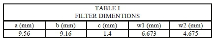
The pedestal resonator offers a designer the ability to make an optimal choice between size, unloaded Q, and second resonance spacing [14], by defining the parameters a, b, w1 and w2. In general, the smaller a and b are, the higher the cut-off frequency of the empty cavity, and the larger the pedestal top needs to be to achieve resonance. This lowers the unloaded Q, but increases the second mode resonance separation. For the filter presented here, a resonator with dimensions as seen in Table I is used, with a resonance frequency of 5 GHz, unloaded Q of 160, and a second mode separation of 6.23 GHz.
III. COUPLING MECHANISMS
The strength of the pedestal SIW structure is that the positive inline couplings, as well as the positive and negative cross-couplings, can easily be implemented, inside the structure. Furthermore, input and output couplings of a wide range of values can be achieved using a grounded via to the input or output line. In this section, each of these couplings are discussed. In all cases, the resonator structure from the previous section is used.
A. Input and output coupling
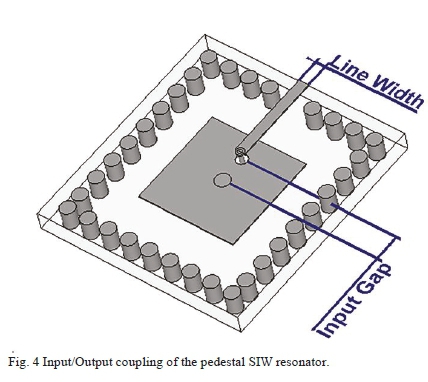
The input and output coupling of coupled-resonator filters are commonly defined in terms of the loaded Q of the first and last resonator respectively. The wider the filter bandwidth, the lower the loaded Q needs to be. In SIW structures, energy typically needs to be coupled from a 50 Ω microstrip or coplanar line to the inside of the resonator, most often by using electric coupling. Here, magnetic coupling is used instead.
The coupling structure, shown in Fig. 4, consists of a 50 ohm coplanar line in the top ground plane of the structure, shorted to the bottom ground plane using a grounded through via. Note that in the figure, the top ground plane is removed for clarity, with only the centre conductor of the coplanar line visible. The via runs through an aperture in the pedestal top to ground, and couples to the magnetic field around the pedestal base. By controlling the separation between the two vias, a very wide range of coupling values can be attained.
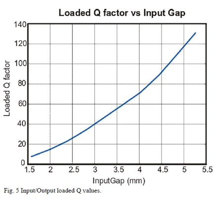
The calculated results can be seen in Fig. 5 where the loaded Q is plotted against the distance between the vias. As the distance decreases, the coupling increases, and the loaded Q decreases. It is clear that a wide range of values is obtained, corresponding to filter bandwidths ranging from below 1% to almost 13%. In comparison to [5] where a 1.14 - 7.14 % bandwidth range is shown, a wider range is achieved in the presented structure.
B. Positive inner-resonator coupling
Given that the pedestal structure can be viewed as a loaded SIW waveguide, positive/magnetic inter-resonator coupling can be realised in the same way as for normal waveguides, i.e. using conventional inductive irises. Figure 6 shows two identical adjacent pedestal resonators separated by a via wall.
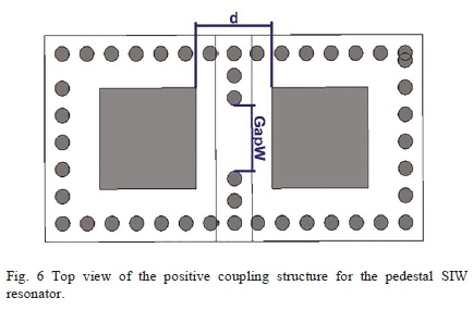
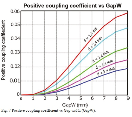
To effect magnetic coupling, an aperture can be formed by simply removing vias to create a gap, as shown. Both the width of the gap, and the pedestal spacing, control the positive coupling coefficient, which is calculated using the standard two-frequency method for identical resonators.
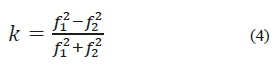
Where k is the coupling coefficient, while f1and f2correspond to the even and odd resonant frequencies.
The calculated results are plotted in Fig. 7, displaying the positive coupling coefficient against the gap width (GapW) for various pedestal spacings (d). As with standard waveguides, the range of coupling values for this type of coupling is large, as a closed wall represents zero coupling, while no wall represents direct coupling. The values in Fig. 7 will for instance enable filters with bandwidths ranging from zero bandwidth up to almost 10%.
C. Negative inter-resonator coupling
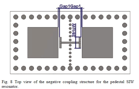
To create negative coupling in standard SIW is more difficult than positive coupling, as the electric field has to be probed in the guide. The range of solutions presented in the introduction of this paper attests to the fact that most existing solutions suffer from some drawback. The pedestal structure however lends itself admirably to this, as the flat top of the pedestal offers an excellent point at which to probe the electric field through simple capacitive coupling [10]. Such a coupling structure can simply be etched in the same way as the pedestal top itself. Due to the placement, the field distribution in the resonator is hardly disturbed, while the simplicity reduces the problems incurred by more complex coupling structures.
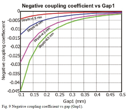
Fig. 8 shows a coupling structure consisting of an I-shaped strip line placed between the resonators on the same layer as the pedestal tops. Coupling can again be calculated using the two-frequency technique. In Fig. 9, the negative coupling coefficient is plotted against the coupling gap (Gap1) for various strip widths (StripW), showing the increase in coupling value as the gap decreases, or the strip width increases. Again, a wide range of coupling values is achieved.
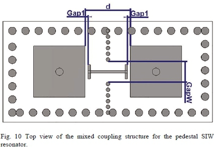
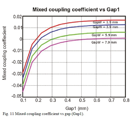
The two coupling mechanisms can also be combined to give a wide range of mixed couplings, which can be changed from negative to positive by simply changing the gap size. Figure 10 shows such a structure, with the coupling values presented in Fig. 11. The proposed structure shows that it is easier to implement mixed-coupling as opposed to other structures such as in [4]. The coupling values obtained with this structure is similar to most coupling structures but is able to obtain a slightly larger range of values in comparison to structures such as in [11].
E. Other publications
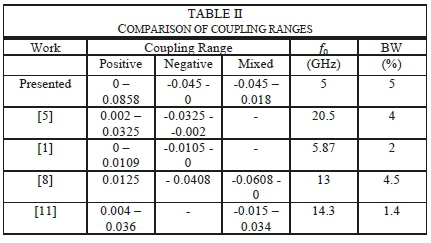
In Table II the coupling ranges of other state-of-the-art SIW coupling mechanisms are compared to this work. In comparison to the designs from [1], [4], [5], [8], [11] and [12] the coupling structures presented evidently offers similar ranges, but with the added benefit of realising both positive and negative couplings in the same structure, without any external lines or slots.
IV. Prototype filter
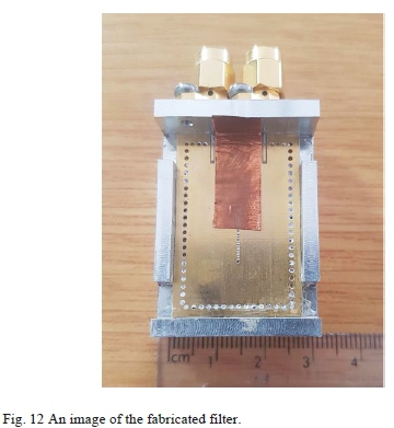
Using the coupling methods described, the filter in Sec. Π was implemented. The fabricated filter is shown in Fig. 12. Copper tape was added to minimize coupling between the input and output coaxial connectors.
The filter was measured using a Keysight PNA-X network analyser, and the measured results are given in Figs. 13 to 15. The manufactured filter shows a frequency shift of 0.22 GHz and a slight increase in bandwidth, due to a difference in the thickness of the post-processed upper substrate layer from that specified originally by the vendor (shown in Fig. 3. To compare the performance of the manufactured filter visually with the simulation without reconstructing the filter, the simulated results were recalculated for a substrate thickness increased by 0.1 mm.
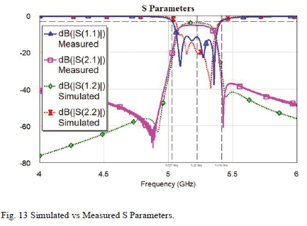
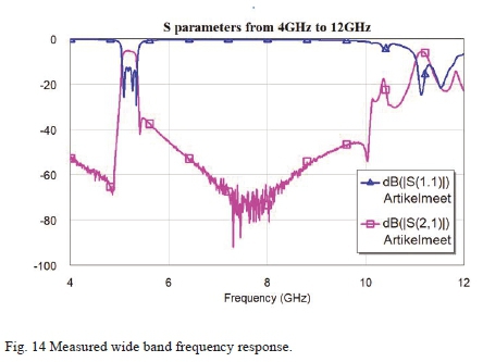
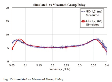
Good agreement is achieved inside and close to the passband, for both the amplitude and group delay responses. Specifically, the group delay and the transmission zero in the stopband, show that both real and imaginary transmission zeros are implemented correctly, therefore both positive and negative cross-couplings are demonstrated. Good correspondence of the bandwidths show that all the inline couplings are accurately implemented, while good return loss agreement shows that the input and output couplings are also implemented correctly. The manufactured filter shows a small increase in insertion loss in comparison to the simulated response, which is due to ideal conductivity used for copper and no surface roughness being taken into account in simulation.
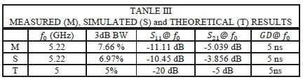
Significant differences can however be seen in the stopband. This is due to coupling between the coplanar feed lines on the top of the substrate, and not the filter itself. This can be reduced by improving the isolation between the feed lines, using physical shielding. The measured, simulated and ideal results are summarized in Table III.
V. Conclusion
A proof-of-concept sixth order cross-coupled SIW bandpass filter is presented for coupled resonator filters requiring both electric and magnetic coupling in the same structure. All coupling mechanisms are discussed in detail, with graphs showing typical achievable values. After compensating for a difference in post-processed layer thickness of the top layer, the measured results are in good agreement with the simulation and theory. From the results it is clear that the use of both positive and negative cross-coupling allows for transmission zeros at real frequencies, as well as group delay equalization. The SIW pedestal resonator structure lends itself very well to the implementation of both positive and negative cross-coupling.
Acknowledgment
The authors would like to thank the NRF and Cobham plc for financial support of this project, Dassault Systèmes for the use of CST Microwave Studio, as well as Trax Interconnect, Wessel Croukamp and Gift Lecholo for the manufacturing of the filter.
References
[1] S. Sirci, F. Gentili, J. D. Martinez, V. E. Boria, and R. Sorrentino, "Quasi-elliptic filter based on SIW combline resonators using a coplanar line cross-coupling," 2015 IEEE MTT-S International Microwave Symposium, IMS 2015, pp. 2-5, 2015.
[2] H. Wang and Q. X. Chu, "An inline coaxial quasi-elliptic filter with controllable mixed electric and magnetic coupling," IEEE Transactions on Microwave Theory and Techniques, vol. 57, no. 3, pp. 667-673, 2009. [ Links ]
[3] A. Atia, A. Williams, and R. Newcomb, "Narrow-band multiplecoupled cavity synthesis," IEEE Transactions on Circuits and Systems, vol. 21, no. 5, pp. 649-655, 1974. [Online]. Available: http://ieeexplore.ieee.org/document/1083913/ [ Links ]
[4] G. Lojewski and N. Militaru, "Design of Microwave Band-Pass Filters with Cross-Couplings based on Electromagnetic Simulation and Linear Circuit Optimization," TELECOMUNICAJII Anul LI, no. 1, pp. 49-53, 2008.
[5] X. P. Chen and K. Wu, "Substrate integrated waveguide crosscoupled filter with negative coupling structure," IEEE Transactions on Microwave Theory and Techniques, vol. 56, no. 1, pp. 142-149, 2008. [ Links ]
[6] S. Sirci, M. A. Sanchez-Soriano, J. D. Martianez, V. E. Boria, F. Gentili, W. Bosch, and R. Sorrentino, "Design and Multiphysics Analysis of Direct and Cross-Coupled SIW Combline Filters Using Electric and Magnetic Couplings," IEEE Transactions on Microwave Theory and Techniques, vol. 63, no. 12, pp. 4341 -4354, 2015. [ Links ]
[7] D. Ming, S. Dongya, M. Chaojun, and Z. Xiupu, "A cascaded six order bandpass siw filter using electric and magnetic couplings technology," Presented at APCAP Xi an, China, 2017.
[8] D. Jia, Q. Feng, Q. Xiang, and K. Wu, "Multilayer Substrate Integrated Waveguide (SIW) Filters with Higher-Order Mode Suppression," IEEE Microwave and Wireless Components Letters, vol. 26, no. 9, pp. 678-680, 2016. [ Links ]
[9] L. S. Wu, X. L. Zhou, and W. Y. Yin, "A novel multilayer partial h-plane filter implemented with folded substrate integrated waveguide (FSIW)," IEEE Microwave and Wireless Components Letters, vol. 19, no. 8, pp.494-496, 2009. [ Links ]
[10] C. Wang and K. A. Zaki, "Full-wave modeling of electric coupling probes in comb-line resonators and filters," IEEE Transactions on Microwave Theory and Techniques, vol. 48, no. 12, pp. 2459 2464, 2000. [ Links ]
[11] B. Potelon, J. F. Favennec, C. Quendo, E. Rius, C. Person, and J. C. Bohorquez, "Design of a Substrate Integrated Waveguide (SIW) filter using a novel topology of coupling," IEEE Microwave and Wireless Components Letters, vol. 18, no. 9, pp. 596-598, 2008. [ Links ]
[12] K. Gong, W. Hong, Y. Zhang, P. Chen, and C. J. You, "Substrate integrated waveguide quasi-elliptic filters with controllable electric and magnetic mixed coupling," IEEE Transactions on Microwave Theory and Techniques, vol. 60, no. 10, pp. 3071-3078, 2012. [ Links ]
[13] B. Koh, B. Lee, S. Nam, T. H. Lee, and J. Lee, "Integration of Interresonator Coupling Structures with Applications to Filter Systems with Signal Route Selectivity," IEEE Transactions on Microwave Theory and Techniques, vol. 64, no. 9, pp. 2790-2803, 2016. [ Links ]
[14] P. Meyer and S. Nassar, "Pedestal substrate integrated waveguide resonators and filters," IET Microwaves, Antennas & Propagation, pp. 1-8, 2017.
[15] R. J. Cameron, "General coupling matrix synthesis methods for Chebyshev filtering functions," IEEE Transactions on Microwave Theory and Techniques, vol. 47, no. 4, pp. 43 3 -442, 1999. [ Links ]

Leanne Johnson (M'19) Received her B.Ing (Cum Laude) in Electrical Engineering specialising in telecommunications from Stellenbosch University, South Africa in 2016. She continued there as a Master's student in 2017, and was upgraded to a PhD in October of 2018.
She is currently registered at Stellenbosch University as a full time PhD student. She has also worked on microwave filters with Prof. Benjamin Potelon at Université de Bretagne Occidentale in France.

Prof. Petrie Meyer (S'87-M'88) is a Distinguished Professor in Electromagnetics and Microwaves at Stellenbosch University in South Africa. He received his PhD in 1995 from the University of Stellenbosch, on numerical analysis of microstrip circuits using the Method-of-Lines, and his DEng in 2019. He is currently the Vice-Dean (Research) of the Faculty of Engineering at Stellenbosch University.
He has worked actively in the fields of passive network design, optimization, and surrogate modelling, and has authored or co-authored more than 100 technical journal and conference papers. Since 2010 he has been involved in the design of microwave filters and antenna elements for the Square Kilometre Array (SKA) radio astronomy antenna, and the South-African precursor telescope, MEERKAT. In 2004, he was awarded the South African THRIP prize for human resource development, and in 2007 the international CST prize for a published journal paper making use of CST. He has served as chairman for the local IEEE AP/MTT conferences since 2005 and as technical chair for the 1999 IEEE Africon conference, as well as chairman of the IEEE South Africa Section during 1996-1997. He serves as regular reviewer for IEEE, IET and Wiley microwave journals. In 2009, he was elected Fellow of the South African Institute for Engineers.

Dr. Elmine Meyer (M'11) received a BSc in electrical engineering with minors in computer science and mathematics from Fairleigh Dickinson University, USA in 2013. She obtained a PhD in electronic engineering from Stellenbosch University, South Africa in 2018.
She was employed at Stellenbosch University as a Junior Lecturer from July 2015 to May 2018, and as a Lecturer from May 2018 until October 2019. She is currently a Postdoctoral Researcher at Eindhoven University of Technology, Netherlands. Her current research interests include mmWave systems for 5G, radio interferometers and the calibration thereof, and tunable microwave filters.

