


Services on Demand
Article
 English (pdf)
 Article in xml format
 Article references
Indicators

Related links
-
 Cited by Google
 -
 Similars in Google
Share

 Permalink
SAIEE Africa Research Journal
On-line version ISSN 1991-1696
Print version ISSN 0038-2221
SAIEE ARJ vol.110 n.3 Observatory, Johannesburg Sep. 2019
ARTICLES
Electrical Model of Phase-to-Woodpole Bird Electrocution
Andreas A. BeutelI; Bruce W. McLarenII; Hendri J. GeldenhuysIII; Megan K. MurisonIV; W. Constant HoogstadV; Nkateko E. KhozaVI; Matimba L. MathebulaVII; John M. Van CollerVIII; Robert A. BranfieldIX; Rudi KrugerX
IIs with Eskom Holdings SOC Ltd, Rosherville, Gauteng, South Africa (e-mail: BeutelAA@eskom.co.za)
IIIs with Eskom Holdings SOC Ltd, East London, Eastern Cape, South Africa (e-mail: mLarenB@eskom.co.za)
IIIIs with Eskom Holdings SOC Ltd, Rosherville, Gauteng, South Africa (e-mail: GeldenHJ@eskom.co.za)
IVIs with the Endangered Wildlife Trust, Modderfontein, Gauteng, South Africa (e-mail: meganm@ewt.org.za)
VIs with the Endangered Wildlife Trust, Modderfontein, Gauteng, South Africa (e-mail: ConstantH@ewt.org.za)
VIIs with Eskom Holdings SOC Ltd, eMalahleni, Mpumalanga, South Africa (e-mail: KhozaEN@eskom.co.za)
VIIIs with Eskom Holdings SOC Ltd, Rosherville, Gauteng, South Africa (e-mail: MathebML@eskom.co.za)
VIIIIs the University of the Witwatersrand, Braamfontein, Gauteng, South Africa (e-mail: John.VanColler@wits.ac.za)
IXIs with Eskom Holdings SOC Ltd, East London, Eastern Cape, South Africa (e-mail: BranfiR@eskom.co.za)
XIs with Eskom Holdings SOC Ltd, Kimberley, Northern Cape, South Africa (e-mail: KrugerR@eskom.co.za)
ABSTRACT
The electrocution of large birds such as eagles and vultures when making simultaneous contact between a phase conductor and the top of a pole on medium voltage woodpole distribution lines is addressed. System (phase-to-phase) voltages of 11 kV, 22 kV and 33 kV are covered. This phenomenon has been investigated by measurement of the resistance of poles used in the field, as well as measurement of the impedance of recently deceased birds. This has previously been used to compile a simple electrical model for 22 kV systems. This paper compiles a detailed model that is used to estimate the risk posed to large birds by this mode of electrocution for all three voltage levels. The results show that only a few scenarios exist whereby a bird may be at risk, which ties in with field experience. Details of how the wood and bird resistance was measured are also included, as are details of calculations performed.
Keywords: Power distribution lines, power system simulation, electrical safety, environmental impact.
I. Introduction
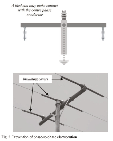
Large birds such as eagles and vultures are at risk of electrocution on the structures of medium voltage (MV) overhead distribution lines because their wing-span is comparable with clearances at these voltages (mostly in the 11-33 kV range). Such electrocutions may occur in phase-to-phase or phase-to-earth mode. The two modes are illustrated in Fig. 1. The former occurs when a bird makes simultaneous contact between two energised objects, usually two phase conductors.

Phase-to-earth electrocution occurs between a phase conductor and an earthed object, such as a steel tower. Phase-to-phase electrocution can be prevented by either placing the phases in such a way that the bird cannot make contact with more than one conductor, e.g. by placing at least the outside two phases below a cross-arm or by covering one or more conductors with an insulating cover (at least the centre phase), as shown in Fig. 2. Phase-to-earth electrocution on conductive structures, e.g. those made out of steel, may be prevented by using an insulating cover for phase conductors and/or by providing the cross-arm with an insulating cover [1,2].
Poles made out of wood, on the other hand, rely on the insulating properties of the woodpole to ensure adequate insulation coordination, as well as to protect the bird. However, some (infrequent) cases of phase-to-earth (referred to as "phase-to-pole" going forward) mode have been observed in the field [2,3], showing that birds may still be at risk of electrocution in this way in certain cases. The assumption is that the wood may be sufficiently conductive in some instances to put a bird in danger.
It was therefore decided to investigate this further by measuring the resistance of woodpoles used on MV lines, and by measuring the impedance of recently deceased birds [2]. The results of these measurements were used to compile a simple model to estimate the risk posed to such birds. The results show that the risk is relatively small [2]. However, a more detailed model was required, since aspects such as capacitance, source impedance and pole earth footing resistance were not included. The aim of this paper is to present this detailed model, as well as the results of various scenarios modelled. The result is a more accurate estimate of the risk of bird electrocution.
The paper is structured as follows: Section II summarizes available literature, section III describes the model, while section IV shows how the model was implemented for 22 kV systems and summarizes the values used for the various parameters in the model, including how the parameters were experimentally determined. Section V presents the results of applying the model to various scenarios, including extension of the model to 11 kV and 33 kV voltages. The work is then discussed and concluded.
II. Previous Work
A. Electrical Properties of Wood
Darveniza [10] studied the conductivity of Australian wood, and found that new wood can have a resistance of in the range of 10 to 50 times lower than seasoned wood. Wood was found to take approximately 9 months to reach a steady-state resistance, which is in contrast to the several years found for South African wood [2]. However, Darveniza noted that wood
treated with creosote, as is the case in South Africa, dried slower than that treated with Copper Chrome Arsenate (CCA). The lowest resistance measured was 1 kΩ, but typical values were 20 kΩ and above; this is lower than the 45 kΩ determined for South African wood [2]. The highest resistance presented in [10] is several ΜΩ, while the resistance shown in [2] reached into the GΩ range for older poles. Wood treatment method has a significant effect on its resistance, as well as on the properties of wetted wood, but not in all cases [10].
Sokolowski et al [12] measured the capacitance of Australian wood to be in the range of less than 0.1 nF to 5 nF. It was also found that the resistance of wood could be below 1 kΩ at applied voltages of higher than about 25 kV. The resistance of dry wood was found to be more dependent on voltage than wet wood; the resistance of dry wood being significantly higher at lower voltages. Wetting the wood resulted in resistances of down to about 100 Ω (the other literature reported here indicates that such a low resistance is not likely to occur often).
Katz et al [13] studied North American wood and considered only d.c. resistance. Resistances per foot wood length were found to fall in the range of 100 kΩ to 100 ΜΩ, depending on moisture content and relative humidity, with salt-treated wood generally having a lower resistance than that treated with pentachlorophenol or creosote. Moisture content was found to reduce the resistance by several orders of magnitude, in some cases, to much less than the above value of 100 kΩ.
Filter et al [11] proposed a ladder model of a wood pole to take into account the fact that a pole is not homogenous. North American pole species, treatment type and the effect of rain are also taken into account. It is shown that resistance varies significantly along a pole.
Ragon et al [14] performed a study on the conductivity of wood utility poles using Southern Pine (a North American species) that had been commercially pressure treated with Creosote, Pentachlorophenol, Copper Naphthenate and CCA. Large differences were found between treatment methods, but all measurements were within one order of magnitude of one another for the same moisture content. Conductivity changed by up to eight orders of magnitude with moisture content from dry to 52%. Resistivity at about 15% moisture content varied from 470 kΩ/m for Pentachlorophenol-treated wood to 3 GΩ/m for wood treated with Chromated Copper Arsenate. Resistances varied from 230 GΩ/m for dry wood to 300 Ω/m for saturated wood, as an indication.
A Swedish study [15] measured the resistance of poles treated with arsenic, salt and creosote and of different ages. The lowest resistance measured was 28 kΩ for the arsenic pole, the highest was 1.5 ΜΩ for the pole treated with salt. Manual wetting of the poles treated with arsenic and fast-dry salt resulted in a significant reduction in resistance, but this was not true for a slow-dried, salt preserved pole.
The results presented in this section show that the properties of wood, the natural variation of those properties, the treatment method and the ambient climatic conditions all significantly affect the electrical properties of the wood. This also shows that poles do not have homogenous resistivity.
B. Electrical Properties of Birds
Sparrey et al [8] found that farm birds, such as hens and ducks, have an impedance in the range of 800 to 7,000 Ω and that 120-150 mA is sufficient to induce ventricular fibrillation in 90% of birds. A reference quoted in [6] mentions that a much lower current of 9-12 mA (applied at 400-500 V) is sufficient to cause convulsions in birds. A different reference quoted in [6] found that wet eagle feathers burnt when subjected to 5-7 kV, but that no measureable current flowed on dry feathers at 70 kV. This is in broad agreement with the results of measurements of recently deceased specimens of wild birds in South Africa, which is covered in Section IV-C. No sources of information on the capacitance of birds were found in the literature.
C. IEEE Standards
IEEE Std 1651 [16] covers the mitigation of bird electrocutions, collisions and of bird-related and nest-related power outages. The risk posed by conductive wood is not mentioned, it is therefore assumed that the risk is not considered large enough to include. The following mitigation measures are covered:
• Structure reconfiguration to provide adequate separation between conductive parts of different polarity (an example is shown in Fig 2a),
• Retrofit of insulating covers to prevent simultaneous contact between two items at different voltages (an example is shown in Fig 2b), and
• Retrofitting of alternative bird perches.
It is advised in [16] that insulating covers are chosen and installed with care to ensure that they perform as required. IEEE Std 1656 [17] provides a guide for testing equipment intended for mitigating wildlife interactions on overhead low and medium voltage networks.
III. Description of the Model
The model is illustrated in Fig. 3. The components in Fig. 3 are defined as follows:
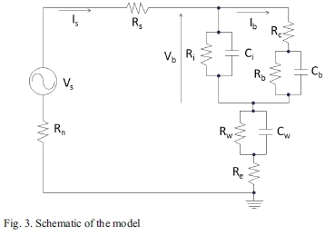
• Vs= phase-to-earth supply voltage.
• Vb= voltage across the bird (voltage across Rb//Cb in series with Rc).
• Is= current drawn from the supply.
• Ib= current flowing through the bird.
• Rs= source (phase conductor) resistance.
• Ri= (phase) insulator (surface) resistance.
• Rc= contact resistance between the bird and the conductor.
• Rw= wood resistance.
• Re= pole footing (earthing) resistance.
• Rn= supply neutral earthing resistance.
• Ci= (phase) insulator capacitance.
• Cb= bird capacitance.
• Cw= wood capacitance.
The previous (simplified) model [2] only took into account bird and wood resistance. The other series impedances (resistances), i.e. conductors, pole earthing, contact resistance and neutral compensation, were not included. The effect of any leakage current across the phase insulator was also not included - this current is electrically in parallel with the bird. Capacitance was also not included in the model.
IV. Model Implementation
A. Model Parameters
The parameters are listed in Table I. Several assumptions had to be made when selecting the values in Table I, these assumptions were based on the following:
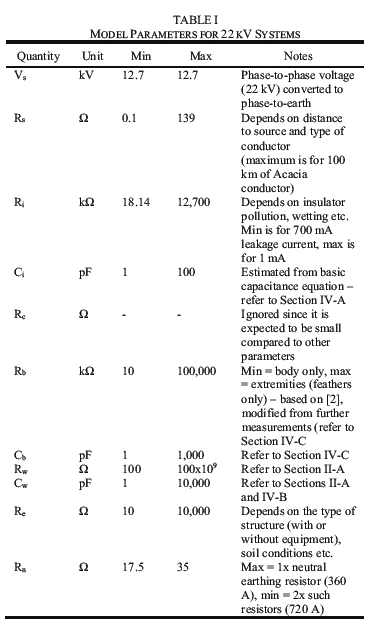
1. Bird impedance is assumed to be mostly resistive, as explained in Section IV-C.
2. Insulator capacitance was estimated by modelling a parallel plate capacitor with relative permittivity of 7 (for rubber [19]), 30 cm separation and 10 cm diameter end fittings, giving a capacitance of 1.6 pF.
3. The inductance of the supply neutral earthing resistance (Rn) is negligible - the maximum value of the allowable inductive reactance (Xn) specified by Eskom is less than the minimum allowed resistance [4].
4. Ranges of the various parameters were used, as shown in Table I, to determine the sensitivity of the results to each parameter.
B. Determination of Wood Capacitance
Wood capacitance was measured using a dielectric response analyzer [5]. Two 0.5 m wood samples were tested, one about six years old and the other approximately three years old. The wood sample ends were prepared to have a smooth and flat finish. Aluminum plates were fixed onto each end and had holes drilled at the corners and placed at the flat ends of the wood sample. Nylon strings and turnbuckles were then used to tighten the plates against the sample and graphite was used to ensure that the entire surface of the sample is conductive. This is shown in Fig. 4.
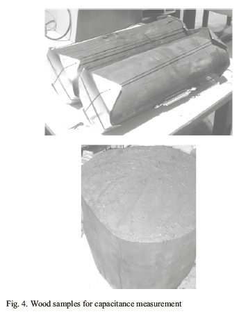
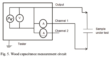
The suitability of the measurement was tested by measuring the capacitance of a known capacitor; this was accurately achieved. The test circuit is shown in Fig. 5. A tan-delta measurement was performed on the samples. The tester is capable of performing dielectric measurements over a frequency range of up to 5 kHz. The output and channel 1 connections were connected to the aluminum plates by means of cables provided with the instrument. It can be seen that the connection allows for simultaneous voltage and current measurements. The input voltage amplitude selected was set to 200 V; however a lower voltage may be used if required. The instrument calculates the capacitance of the sample under test from the measured voltage and current.
The results found capacitances that varied from 1.81 pF for dry wood to 261 pF when the wood is wet. This is at the lower end of the values reported in the literature for Australian wood in Section II-A.
C. Bird impedance estimation
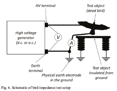
The test method used is illustrated in Fig. 6. This shows that a voltage was applied to recently deceased birds and the current was measured. Dividing the two gives the impedance. Voltage was applied in steps up to approximately 10 kV, as this is an approximation of the phase-to-earth voltage on a 22 kV phase-to-phase system. Most of the tests were performed using d.c. voltage, since only such a generator was available for all tests. Some tests were repeated using a.c. voltage (where available) to obtain an idea of the effect of capacitance on the impedance.
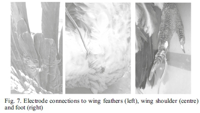
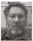
The voltage was applied in different modes: between wing (feather) tips, between a shoulder and a foot (no feathers involved) and between shoulders (again no feathers involved). The three connection points are illustrated in Fig. 7. The test specimens were three Cape Vultures (Gyps coprotheres) and one Secretary bird (Sagittarius serpentarius). Note that all birds tested were already dead before testing was performed, and were not killed or harmed in any way in order to perform these tests.
The results for the Cape Vultures are shown in Fig. 8. This figure shows the following:
• The impedance between wing tips is high for birds 1 and 2, as previously found [6], but is approximately two orders of magnitude higher than for bird 3. These tests were all performed under d.c. voltage.
• The test was repeated under a.c. voltage for bird 2, with the voltage dropping by two orders of magnitude. The reason for this is expected to be the capacitance of the bird's body.
• The impedance is substantially lower for both the shoulder-shoulder and shoulder-foot tests - four to six orders of magnitude. This is again expected from the literature [6].
• The difference between a.c. and d.c. is less marked for the shoulder-shoulder and shoulder-foot tests.
The results obtained for the Secretary bird are listed in Table II.
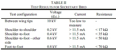
Since most of the tests were performed under d.c. voltage, the results are assumed to be resistive, i.e. these values are used to inform Rb in the model. Cb was estimated by modelling the bird as parallel-plate capacitor with a relative permittivity of 2800 (determined for chickens [18]), separation of 1 m and round electrodes with 5 cm radius. This gives a capacitance of 195 pF.
D. Modeling Software
The model was implemented using Microsoft Excel®. Correct implementation of the model was checked using the free circuit simulator LT Spice [7]; a calculation for an arbitrary set of parameters (listed in Table III) was used. The results obtained for bird voltage and current (Vb and Ib in Fig. 3) were 3.43 kV and 201.9 mA using the Excel model and 3.43 kV and 201.8 mA by manual calculation. The calculation therefore gave acceptably accurate results.

V. Simulation Results
A. 22 kV - All Resistances at their Minimum Values
The first set of simulations was performed with all resistances set at their minimum values and all capacitances set at their maximum values. The aim was to approximate close to the worst case situation. The values of interest are, once again, bird voltage and current (Vb and Ib) and are plotted in Fig. 9. Comparing the obtained values of Ib to the current required to induce ventricular fibrillation in 90% of farm birds (120 mA [8]), shows that birds could theoretically be in significant danger since several data points are above this value. However, Section II-A shows that wood resistance is in most cases greater than 20 kΩ, resulting in only a small set of scenarios that are expected to result in a hazard. However, if a lower "safe" bird current threshold of 4 mA is used [9], then a greater hazard can be expected. Note also that almost full phase-to-earth voltage appears across the bird at lower wood resistances - this is in effect a voltage divider between the parallel bird-insulator combination and the remainder of the circuit.
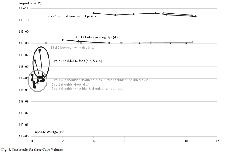
B. 22 kV - insulator resistance set to maximum
Next, the insulator resistance, Ri, was set to maximum, with the intention of reducing the current flow in parallel with the bird - this was hence also expected to be close to the worst case. The results are shown in Fig. 10, with the smallest and largest values from Fig. 9, and show that there is in most cases only a small increase in the current flow through the bird, as expected.
C. Series resistance increased
The simulations were then repeated with the only change being the pole footing resistance, Re, being set to its maximum value. The aim of this was to illustrate the effect of changing any of the resistances in series with the bird and wood. The results are plotted in Fig. 11, and show that Re (and by extension Rs, Rn and Rc) has only a small effect on Ib and Vb. Again this is expected. Note also that Re is very unlikely to reach 10 kO, and is less than 1 in most cases.
D. Effect of capacitance
Measurements in the laboratory revealed a significant variation in wood capacitance, as shown for Cw in Table I. Bird and insulator capacitance (Cb and Ci) is also expected to vary. The simulations were therefore repeated using the minimum capacitances listed in Table I, with the aim of estimating the sensitivity of the results to capacitance. Resistances were all set at their minimum, except for Ri which was at its maximum. The results plotted in Fig. 12 show that the effect of capacitance is significant at lower bird body currents and voltages and at higher bird and wood resistances.
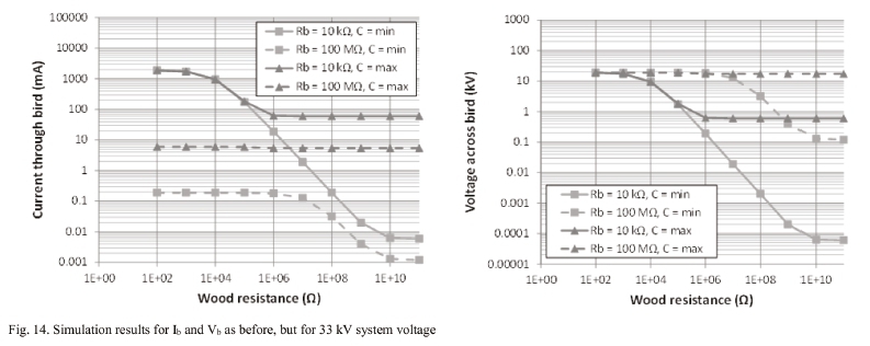
E. Extension to 11 kV and 33 kV systems
The parameters listed in Table IV were used, the aim of which was to investigate the relative risk at the three voltage levels and to determine the sensitivity of the results to variation in capacitance. The results are plotted in Fig. 13 and Fig. 14 and show a similar effect to that found at 22 kV (Fig. 12). The anticipated currents are larger for 33 kV system voltage, hence the risk is also higher. This is expected since the only parameter that changes with voltage in the model, Ri, has only a small effect on the results.
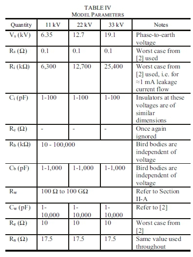
Fig. 12, 13 and 14 show that capacitance does indeed affect the bird current above 100 kΩ in all three cases, but only at current levels at which the bird is most likely not in danger. Capacitance can therefore safely be ignored for practical purposes.
VI. Discussion and Conclusions
It was mentioned above that 120 mA [8] can be used as the threshold current above which a bird may be considered at risk. However, since this is a 90% fibrillation level, lower currents may also pose a threat. A lower current threshold that could therefore be considered is 4 mA [9]. The authors' field experience and the literature indicates that the hazard is low, indicating that the values from [8] are more likely closer to the actual situation. In any case, there is no available experimental data for wild birds to confirm this.
Additional factors that are expected to reduce the risk are that most insulators are likely to flash over when leakage current peaks exceed about 200 mA and that noise arcing activity at 100 mA leakage current may repel birds. The fact that dry feathers are very good insulators reduces the risk further.
Capacitance of bird and wood has a significant effect on the results, but because this mostly at higher resistances the effect for practical purposes is not substantial. A factor that may require consideration in future variation in resistance with applied voltage, but again this is not expected to have a practical effect.
The results have substantiated the very limited electrical characteristics listed for wild birds in the literature, in that a significant difference between the impedance of such birds' bodies and their feathers was found. The effect of whether a.c. or d.c. voltage was used was also found to be significant.
It is therefore clear that in order to obtain an even more accurate model of the electrical behaviour of a wild bird requires significantly more work. This would be time-consuming, since a large number of specimens would be required, and is hence disproportionate to the value gained, since such electrocutions are rare. Therefore, for practical purposes the model is sufficiently accurate across the 11-33 kV voltage range.
While the results show that a bird is only at a small risk of being electrocuted in phase-to-pole mode on an MV overhead power line in general, the unique wood properties and climatic conditions at each location being considered should be taken into account before deciding on a level of risk for that location. Note also that this conclusion was reached for distribution lines in South Africa that have been in service for more than a certain number of years.
Acknowledgment
The authors gratefully acknowledge the assistance of the Crown Rehabilitation and Conservation Wildlife Centre with some of the bird impedance tests. The assistance of Samuel Motshegwa and Nishanth Parus of Eskom Holdings SOC Ltd with certain tests is also acknowledged.
References
[1] G. Göcsei, Β. Németh, R. Cselkó, I. Berta and Β. Torda, "Bird protection on medium voltage power lines", in Proc. 23rJ CIRED, Lyon, France, 2015, Paper 1288.
[2] A. A. Beutel, Β. W. McLaren, R. Branfield, C. Hoogstad, H. J. Geldenhuys, N. Khoza, M. D. Ntshani, J. M. Van Coller, R. Kruger, "Electrocution risks to endangered birds on MV overhead lines - South African experiences", in Proc. 46,h CIGRE Session, Paris, France, 2016, Paper C3-102.
[3] R. N. Lehman, "Raptor electrocutions on powerlines: Current issues and outlook", U.S. Geol. Surv., Resource Div., Snake River Field Stat., Boise, ID, USA, vol. 14, 1999.
[4] "Distribution Specification - Part 7: Specification for combined three-phase neutral electro-magnetic couplers (NECs) with neutral earthing resistors (NERs) and auxiliary transformers", Eskom Holdings SOC, Distribution Specification 34-1690, Feb. 2009.
[5] Omicron Dirana Dielectric Response Analyser. [Online]. Available: https://www.omicronenergy.com/fileadmin/user_upload/pdf/literature/DIRANA-Brochure-ENU.pdf, Accessed on: Oct. 3 2016.
[6] Avian Power Line Interaction Committee, "Suggested practices for avian protection power lines: the state of the art in 2006", PIER Final Project Report CEC-500-2006-022, USA, 2006, pp. 48-49.
[7] Linear Technology Corporation, LT Spice version 4.23k, 25 March 2016. [Online]. Available: http://www.linear.com/.
[8] J. M. Sparrey, P. J Kettlewell, Μ. E. R. Paice, W. C. Whetlor, "Development of a constant current water bath stunner for poultry processing", Journal of Agricultural Engineering Research, vol. 56, 1993, pp. 267-274. [ Links ]
[9] A.A. Beutel, B.W. McLaren, H.J. Geldenhuys, J.M. Van Coller, C. Hoogstad, N. Khoza, R. Kruger, R. Branfield, "Design of MV overhead lines to maximise bird safety", in Proc. 24'k CIRED, Glasgow, UK, 2017, Paper 272.
[10] M. Darveniza, "Electrical resistance of wood and leakage current effects", in Electrical properties of wood and line design, University of Queensland Press, 1980, ch 6.
[11] R. Filter and J.D. Mintz, "An improved 60 Hz woodpole model", IEEE Trans. Power Delivery, vol. 5, no. 1, pp. 442^448, Jan. 1990. [ Links ]
[12] P. Sokolowski and X. Yu, "Characterizing impedance profiles for leakage currents from HV insulators on wooden poles", IEEE Trans. Dielectrics and Electrical Insulation, vol. 23, no. 3, pp. 1338-1346, Jun. 2016. [ Links ]
[13] A. Katz and D. Miller, "Effects of Some Preservatives on the Electrical Resistance of Red Pine", in Proc.American Wood-Preservers' Association, vol. 59, 1963, pp. 204-217. [ Links ]
[14] K. Ragon, P. Donohoe, M. Freeman, "The Electrical Properties of Treated Wood with a Focus on Utility Pole Conductivity: Part II", in Proc. American Wood Preservation Association, vol. 106, 2010, pp. 153-167.
[15] M. Wahlberg and S. Rönnberg, "Case study on electrical conductivity in wood poles", Luleâ University of Technology Tech. Rep., ISBN 978-91-7583-828-1,2017.
[16] IEEE Guide for Reducing Bird-Related Outages, IEEE Std 1651™2010, 2011.
[17] IEEE Guide for Testing the Electrical, Mechanical, and Durability Performance of Wildlife Protective Devices on Overhead Power Distribution Systems Rated up to 38 kV, IEEE Std 1656™2010, 2011.
[18] A. A. S. Rabih, Mumtaj Β. K. Rawther and T. bin I., Z. A. Burhanudin, "Effective Relative Permittivity of Properly Slaughtered and Non Properly Slaughtered Chicken Using Dielectric Mixing Rules", in Proc. National Postgraduate Conference, Sep 2011, Kuala Lumpur, Malaysia.
[19] Wikipedia entry, "Relative permittivity". [Online]. Available: https://en.wikipedia.org/wiki/Relative_permittivity. Accessed: Jan 9 2019.
Submitted for review on March 27th 2018

Andreas A. Beutel was born in Johannesburg, South Africa. He graduated with BSc(Eng), MSc(Eng) and PhD degrees in Electrical Engineering from the University of the Witwatersrand, Johannesburg, South Africa, in 1998, 2000 and 2007 respectively. He is currently Chief Engineer at Eskom Holdings SOC Ltd, Rosherville, Gauteng, South Africa. He was previously a Design Engineer at CBl-electric: Low Voltage. His research interests include electrical distribution, insulation and safety, as well as lightning and surge protection. Dr. Beutel is a registered professional electrical engineer in South Africa, a member of the Institution of Engineering and Technology and a Fellow of the South African Institute of Electrical Engineers.
Bruce W. McLaren was born in East London, Eastern Cape, South Africa. He holds a National Diploma (Electrical), a Graduateship in Electrical Distribution from the City and Guilds of London Institute and a Post Graduate Diploma in Project Management.
He is currently a Senior Technologist at Eskom Holdings SOC Ltd, East London, Eastern Cape, South Africa. He was previously employed in the Planning and Design section of the Electricity Department, East London Municipality.
Mr. McLaren's research interests include medium and low voltage electrical distribution, including applied insulation, safety and lightning mitigation. He is a registered Professional Electrical Technologist in South Africa, and a member of the South African Institute of Electrical Engineers.

Hendri J. Geldenhuys was born in Brakpan, South Africa, in 1956. He graduated with BEng (Electrical), BEng Honours (Electrical) and MEng (Electrical) degrees from the University of Pretoria and a PhD from the University of the Witwatersrand, Johannesburg, South Africa.
He is currently a Corporate Specialist at Eskom Holdings SOC Ltd, South Africa. He has been with the CS1R South Africa from 1979 to 1994. His expertise stretches across the spectrum of electrical utility technical and business issues. His research focus is on high voltage insulation, electrical engineering for distribution systems as well as lightning, its impacts and lightning protection. Dr Geldenhuys is the President of the South African Institute of Electrical Engineers.

Megan K. Murison was born in Johannesburg, South Africa. She graduated with a Β Sc Honours in African Vertebrate Biodiversity and MSc in Zoology from Rhodes University, Grahamstown, Eastern Cape, South Africa.
She currently works at the Endangered Wildlife Trust (EWT) in Johannesburg, South Africa, as a Project Manager with the National Biodiversity and Business Network. Her role includes the mainstreaming of biodiversity into South African business.

W. Constant Hoogstad obtained a BCom (Law) degree at the University of Johannesburg, South Africa, and a FGASA qualification. He was a field guide and later reserve manager at Edeni Lodge, Karongwe Private Game Reserve. He later managed other game reserves in South Africa. In 2010 he joined EWT in Johannesburg and is currently Senior Manager Industry Partnerships. Mr. Hoogstad's research interests include raptors and large carnivores.

Nkateko E. Khoza was born in Bushbuckridge, South Africa. He graduated with a Β Sc (Engineering) degree from the University of Kwa-Zulu Natal, Durban, South Africa, in 2010. He is currently an Engineer at Eskom Holdings SOC Ltd, eMalahleni, Mpumalanga, South Africa. His research interests include electrical distribution, insulation and safety.
Mr. Khoza is a registered professional electrical engineer in South Africa and a member of the South African Institute of Electrical Engineers.

Matimba L. Mathebula was born in Tzaneen, Limpopo Province, South Africa, in 1986. He received a National Diploma in Electrical Engineering from Central University of Technology, Free State, South Africa, in 2013. He is currently an Electrical Engineering Technician at Eskom Holdings SOC Ltd, Rosherville, Gauteng, South Africa. Mr. Mathebula's main research interests include high voltage engineering, transmission and distribution lines insulators. He is a registered professional engineering technician in South Africa.

John M. Van Coller was born in Nairobi, Kenya. He graduated with BSc(Eng), MSc(Eng) and PhD degrees in Electrical Engineering from the University of the Witwatersrand, Johannesburg, South Africa, in 1975, 1982 and 1989 respectively.
He is a senior lecturer in the School of Electrical and Information Engineering at the University of the Witwatersrand. He teaches and supervises students in the areas of High Voltage Engineering, Power Systems, Power Electronics and Power System Economics. Dr. Van Coller is a Distinguished Member of Cigre and a member of the Institution of Engineering and Technology.

Robert A. (Bob) Branfield was born in Queenstown, South Africa. He obtained a National Diploma in Engineering Survey from Pretoria Technikon, South Africa, in 1978 and a BCom degree from Rhodes University, Grahamstown, Eastern Cape, South Africa in 1996.
He is currently Senior Consultant, Overhead Lines, at Eskom Holdings SOC Ltd, East London, Eastern Cape, South Africa. For the last thirteen years he has been responsible for the national design standards for 66 kV and 132 kV overhead lines and for the ten years prior to that the national 22 kV overhead lines standards. Mr. Branfield has worked extensively with designers and environmentalists in the industry to make overhead lines more bird-friendly. He is registered with the South African Geomatics Council as a surveyor.

Rudi Kruger was born in Kimberley, Northern Cape, South Africa in 1964. He obtained a National Diploma in Land Survey from Pretoria Technicon, South Africa, in 1990, a National Higher Diploma from the same institution in 1990 and a Master's Degree in Environmental Management from the University of the Free State, Bloemfontein, South Africa, in 1999.
He is currently a Corporate Specialist at Eskom Holdings SOC Ltd, South Africa, and has been in Eskom's service for the past 36 years. He is the Environmental Business Partner for Eskom Distribution and Transmission.
Mr. Kruger is one of the Eskom members who started and designed a partnership between Eskom and EWT in 1996 and has delivered various national and international papers on this Partnership and on Environmental Management.

