


Services on Demand
Article
 English (pdf)
 Article in xml format
 Article references
Indicators

Related links
-
 Cited by Google
 -
 Similars in Google
Share

 Permalink
SAIEE Africa Research Journal
On-line version ISSN 1991-1696
Print version ISSN 0038-2221
SAIEE ARJ vol.109 n.4 Observatory, Johannesburg Dec. 2018
ARTICLES
A study of single transmit antenna selection with modulation
N. PillayI; H. XuII
ISchool of Engineering, Department of Electrical, Electronic & Computer Engineering, University of KwaZulu-Natal, Durban, 4041, South Africa. E-mail: pillayn@ukzn.ac.za
IISchool of Engineering, Department of Electrical, Electronic & Computer Engineering, University of KwaZulu-Natal, Durban, 4041, South Africa
ABSTRACT
Multiple-input multiple-output (MIMO) systems have attracted a vast amount of interest, due to improvements offered in capacity and diversity. However, several challenges still remain. Single transmit antenna selection with modulation (STASM) is an important closed-loop variant of MIMO, and addresses several of its challenges, while achieving full-diversity. On this note, the average symbol error probability (ASEP) of STASM with M-ary quadrature amplitude modulation (M-QAM) and M-ary phase shift keying (M-PSK) is formulated and validates the Monte Carlo simulation results. The formulated ASEP expressions are relatively easy to evaluate. Euclidean distance-based antenna selection for spatial modulation (EDAS-SM) is an innovative closed-loop MIMO scheme that provides many advantages. However, since STASM achieves a full-diversity compared to EDAS-SM, there exists a cross-over point after which its error performance is superior to the latter. For multiple receive antennas, the cross-over point only occurs in the moderate-to-high signal-to-noise ratio region, which may be difficult to achieve in practice. Hence, an adaptive transmit mode switching system based on STASM and EDAS-SM as transmission candidates is proposed. A selection criterion for the transmission candidate is based on minimizing the instantaneous symbol error probability in every transmission interval. By switching between STASM and EDAS-SM, the proposed scheme minimizes the ASEP.
Keywords: Adaptive multiple-input multiple-output, Euclidean distance-based antenna selection for spatial modulation, single transmit antenna selection with modulation.
1. INTRODUCTION
In recent times, there is a ubiquitous demand for improved data rates and reliable transmission due to the success of cellular services, multimedia applications and the internet. In this regard, multiple-input multiple-output (MIMO) systems have gained much interest due to its potential for improvements in terms of capacity, diversity and smart antenna usage. However, there are several challenges that need to be addressed. For example, some of the well-known challenges are inter-channel interference (ICI) at the receiver, the requirement for inter-antenna synchronization (IAS) at the transmitter and multiple radio frequency (RF) chains, increased hardware and computational complexity. On this note, spatial modulation (SM) has been proposed by Mesleh et al. [1, 2] to alleviate these challenges. The key idea of SM is to map information to the index of a transmit antenna element. The corresponding antenna is then activated to transmit a symbol from an amplitude and/or phase modulation (APM) constellation set. This technique has inherent advantages. For example, IAS at the transmitter is not required; there is no ICI at the receiver; furthermore, only a single RF chain is required, consequently also improving energy efficiency. Since its introduction, a vast amount of research into SM has been performed in the research community. This has been primarily three-pronged: improvement of reliability, throughput and decreased system complexity [3, 4]. A key disadvantage of SM is that its potential for transmit diversity is not exploited. On this note, several closed-loop schemes for SM have been investigated [3]. In general, the closed-loop schemes of SM are based on: adaptive modulation, transmit precoding, antenna selection and combinations thereof [3].
Of particular interest, antenna selection for SM was investigated in [5, 6]. In [5, 6], Yang et al. presented three closed-loop transmit mode switching schemes for SM, viz. adaptive SM (ASM), optimal-hybrid SM (OH-SM) and concatenated SM (C-SM). The ASM scheme [5] selects the optimum modulation candidate among several predetermined candidates by maximizing the minimum Euclidean distance (MED) between transmission vectors. The transmitter then employs the selected candidate in the subsequent frame. The OH-SM and C-SM schemes [6] employ the same basic idea; however, in OH-SM, the candidate modes additionally make use of transmit antenna selection. While OH-SM yields superior error performance among these schemes, all impose a relatively high computational complexity (CC). Motivated to reduce the high CC of these schemes, the authors of [7, 8], investigated Euclidean distance-based antenna selection for SM (EDAS-SM). Given NTtransmit antennas, the EDAS-SM scheme searches all possible enumerations of NSMtransmit antennas, where 1 < Nsm <NT, for the enumeration that maximizes the MED between transmission vectors. Substantial improvement in error performance was demonstrated at a significantly lower CC [7]. In [8], by exploiting mirror symmetry, further modifications to EDAS-SM decreased the imposed CC. The CC was reduced even further by Wang et al. [9] by exploiting rotational symmetry. Ntontin et al. [10] presented a suboptimal approach for EDAS-SM by invoking singular value decomposition and the Rayleigh-Ritz theorem, which renders the CC independent of the constellation size.
Meanwhile, another well-known closed-loop MIMO technique, single transmit antenna selection with modulation (STASM) [11-13], exhibits similar advantages to SM. For example, STASM also employs a single active transmit antenna, hence IAS is not required, zero ICI is achieved and a single RF chain is required. Improvements over SM due to the closed-loop strategy, are the full-diversity order, that can be achieved asymptotically [11-13], and zero antenna detection error.
In the literature, the investigation of EDAS-SM has not included benchmarking against STASM. Motivated by the above, the contributions of this paper are as follows: a. The average symbol error probability (ASEP) of STASM with M-ary quadrature amplitude modulation (M-QAM) and M-ary phase shift keying (M-PSK) is formulated, b. Motivated by a comparison between STASM and EDAS-SM, an adaptive transmit mode switching system based on STASM and EDAS-SM as the possible transmission candidates is investigated. The instantaneous symbol error probability (ISEP) is employed as a selection criterion for the transmission candidate. The structure of the remainder of this paper is as follows: In Section 2, the background for EDAS-SM and STASM is presented. The formulation of ASEP for STASM with M-QAM and M-PSK is presented in Section 3. Section 4 includes a comparison of the error performance of STASM and EDAS-SM, which forms a motivation for the resulting proposed adaptive system based on transmit mode switching between STASM and EDAS-SM. Finally, conclusions are drawn in Section 5. Notation: Bold lowercase and uppercase letters are used for vectors and matrices, respectively. [-]T, ||-||frepresent the transpose and Frobenius norm operations, respectively. | | and E{-}are the magnitude and expectation operators, respectively. argminw (-)/argmaxw (-) represents the argument of the minimum/maximum with respect to w. min(-) is the minimum of the argument, ( : )denotes the binomial coefficient,  is factorial and Q (-) denotes the Gaussian Q-function.
2. BACKGROUND
The system model of EDAS-SM is illustrated in Figure 1, which assumes a MIMO configuration with NTtransmit antennas, NR receive antennas and a perfect feedback link to the transmitter.

Given NT transmit antennas, antenna selection is employed, such as to select an enumeration of NSM antennas, where 1 <NSM <NT. The mechanism for antenna selection is discussed shortly. An SM mapper [1, 2] is then employed prior to transmission of the message. The received signal of EDAS-SM is defined as [7, 8]:

where 7 is the average signal-to-noise ratio (SNR) at each receive antenna, HSM= [hi h2 . . . hNsM ]is an NRx NSMsub-matrix of an NRx NTmatrix H with 1 <NSM <NT, and its entries are independent and identically distributed (i.i.d.) complex Gaussian random variables with zero mean and unit variance. The transmit symbol is given by x = eksq, where ek, k Є[1 : NSM], is an NSMx 1 vector with a single non-zero element a =1 located at the k-th position and k represents a transmit antenna index, chosen by mapping log2NSM message bits to the chosen NSM antenna indices. The antenna k is then activated to transmit an M-QAM or M-PSK symbol sq, q Є[1 : M], where  is assumed. n represents the presence of additive white Gaussian noise (AWGN) and its entries are i.i.d. complex Gaussian random variables with zero mean and unit variance. Assuming channel state information at the receiver (CSIR), the optimal detector for EDAS-SM employs the maximum-likelihood (ML) rule and is given as [7, 8]:

where x is the set of all possible sq. In [5, 6], the authors approximate the average bit error probability of EDAS-SM by considering the nearest neighbour approximation of the pairwise error probability (PEP), defined by [5, 6],

where X represents the number of neighbourhood points, xi and x2 are the transmitted and detected symbol vectors, respectively. The set of all possible transmit symbol vector combinations of xiand x2are contained in x1and xn, n Є[1 : 2], is denoted by eksqand dmin(HSM) is the MED between the vectors.
From (4), it is evident that the argument of the Q-function should be maximized to minimize the PEP. Hence, in [5, 6], in order to select the optimal candidate enumeration of NSMtransmit antennas when NTtransmit antennas are employed, the following Euclidean distance-based decision metric is solved, such as to minimize error probability [5, 6],

where the columns of HSm correspond to the elements of the  enumeration of a set of
  possible transmit antenna enumerations.
The computational complexity of (5) was formulated as  [7] and is significantly high, limiting the practicality of the method. In the interest of practical realization of (5), [7] demonstrated the equivalence between (5) and the quantity lselected= argmaxl=1:N(minD(l)), where D(l) is an NSMx NSM sub-matrix of an upper triangular NTx NTmatrix D obtained by deleting the rows and columns that are absent in l. Note, the elements of D are real. For M-QAM, the (i, j)-th element of D is computed as follows [7]:

where the minimum distance between any two QAM symbols is given as  and
and
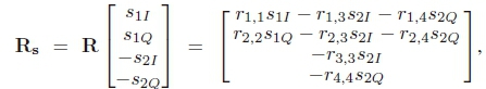
with R a 4 x 4 upper-triangular matrix with zero entries at the locations (1,2) and (3,4) resulting from the QR decomposition of the channel matrix [7]. Rs is computed for pulse amplitude modulation (PAM) constellation points s1l,s2lЄM1and s1q,s2q e M2 for separable QAM signal sets (if an M-QAM signal set can be equivalently written as the Cartesian product of a  constellation set with itself then the QAM signal set is known as separable). Note, M1and M2represent one half of the in-phase and quadrature PAM constellation sets, respectively, due to rotational symmetry [9].
Note, in this paper, only EDAS-SM for M-QAM is considered; however, EDAS-SM for M-PSK is also realized using (5), where only one constellation point is required in the search, due to rotational symmetry [9].
2.2 STASM
Consider a MIMO system with NTtransmit antennas, NRreceive antennas and a perfect feedback link to the transmitter. The STASM scheme assumes a system model as illustrated in Figure 2.

The NRx 1 received signal vector can be defined as [13],

where  is the average SNR at each receive antenna, H is the NRx NTchannel gain matrix defined as
 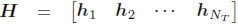 , where hj, j Є[1 : NT], is the j-th column of H, defined as
  . The elements of H are assumed to be i.i.d. complex Gaussian random variables with zero mean and unit variance. x is an NTx 1 transmit vector of the form ejsq, where ej, j Є[1 : NT] is an NTx 1 vector with one non-zero unit entry in the j-th position and sq, q Є[1 : M] is a complex symbol drawn from an M-QAM or M-PSK set. We assume
  . The NRx 1 noise vector n is a complex AWGN vector with i.i.d. elements having zero mean and unit variance. Assuming CSIR, a single transmit antenna is selected based on the largest column
  of the channel matrix, such that
  . The index,
  of the selected antenna is then fed back to the transmitter, which transmits sq from antenna
  , hence ej above is denoted
  .
.
Optimal detection using the ML rule is assumed and is defined as,

3. PERFORMANCE ANALYSIS OF STASM
In [11-13], the theoretical average error probability of STASM for binary phase-shift keying was presented. From searching the open literature, the authors did not come across an extension of the analysis to the case of M-QAM and M-PSK for arbitrary NTand NR. In this section, we extend the analysis to M-QAM and M-PSK with arbitrary NTand NRfor a frequency-flat Rayleigh fading channel. The resulting analysis is relatively easy to evaluate and results in a tight match with simulation results.
3.1 ASEP of STASM with M-QAM
For M-QAM, the ASEP assuming only AWGN is given as [14, (45)]:
For STASM, the probability density function (PDF) of the instantaneous receive SNR, 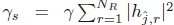 , for a frequency-flat Rayleigh fading channel is defined as

Setting  and employing approximations of the Q-function [14, Section V], the ASEP is formulated as:

The term  , represents a binomial expansion [15], assuming
  ; hence, (11) can be modified to:

The term  represents a multinomial expansion [15]. To solve the integral, we employ the following relation [17, 18]:

and  . Note R(j) is a rectangular window defined as:

Solving the integral in (12), term-by-term, we arrive at:

3.2 ASEP ofSTASM with M-PSK
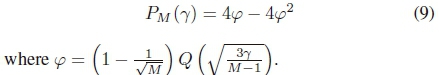
For M-PSK, the ASEP assuming only AWGN is given as [16, (6.16)]:
Accordingly, the ASEP for a frequency-flat Rayleigh fading channel may be formulated as:

Employing an approximation of the Q-function [14, Section V] and simplifying, as earlier, we arrive at:
Integrating term-by-term, we have:

3.3 Numerical Results
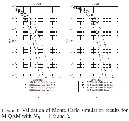
In this subsection, we validate the Monte Carlo simulation results of STASM with M-QAM and M-PSK for NR= 1, 2 and 3. A frequency-flat Rayleigh fading channel and AWGN is assumed. The notation used to denote the MIMO configuration for STASM is STASM-M-QAM/PSK-(NT-1, Nr, M). We consider two spectral efficiencies: 4 b/s/Hz and 6 b/s/Hz. In Figure 3, the results for M-QAM demonstrate a tight match between the Monte Carlo simulation results and the formulated ASEP expression (16). Figure 4 presents the results for M-PSK. Once again, the Monte Carlo simulation results are validated by the formulated ASEP expression (20). A tight match is evident. It is also evident that STASM with M-QAM is superior to STASM with M-PSK; therefore, in the remainder of investigations, we consider M-QAM.

4. PROPOSED ADAPTIVE TRANSMIT MODE SWITCHING WITH STASM AND EDAS-SM
4.1 A Comparison of SM, EDAS-SM and STASM
In this section, we draw comparisons between SM, EDAS-SM and STASM. Since, the M-QAM results for STASM are superior to M-PSK (refer to Figure 3 and 4) we assume M-QAM in the remainder of investigations. Furthermore, a frequency-flat Rayleigh fading channel in the presence of AWGN is assumed. Additionally, CSIR and a perfect feedback link to the transmitter is assumed. The notation used to denote the MIMO configuration employed is as follows: SM-(NT,NR,M), EDAS-SM-(NT-NSM Nr,M ), STASM-(NT-1,NR,M). We first begin by comparing EDAS-SM to SM (this is due to some erroneous results in the literature [8]).
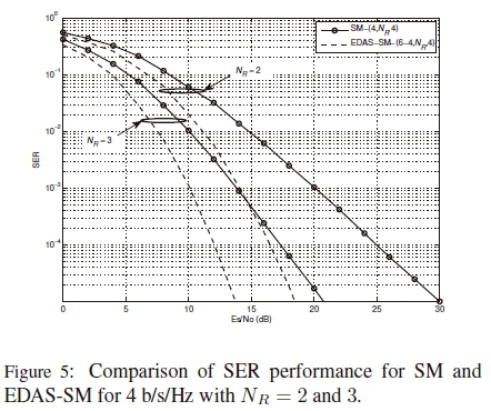
First, we investigate EDAS-SM compared to SM. Simulation results for a spectral efficiency of 4 b/s/Hz are presented in Figure 5 for SM-(4,NR,4) and EDAS-SM-(6-4,Nr,4) with Nr = 2 and 3. It is evident that EDAS-SM yields a significant SNR gain over SM. For example, at a symbol error rate (SER) of 10-5, for Nr = 2 and Nr = 3 an SNR gain of approximately 11.25 dB and 7 dB, respectively, is evident. Furthermore, the slope of the SER curves demonstrate the improvement in diversity.
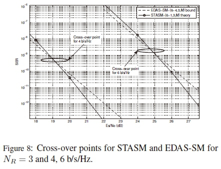
Next, we draw comparisons between STASM and EDAS-SM. For validation purposes, we employ the method used in [19] to generate the SER bound for EDAS-SM, while (16) is employed for STASM. The validation curves for EDAS-SM are generated using the form 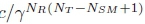 [19], where c is a positive constant determined during simulation (for 4 b/s/Hz, the constant employed for NR= 1,2, 3 are c1= 2.36 x 10⁴, c2 = 1.32 x 10⁶ and c3= 6.98 x 10⁷, respectively, while the constants c4= 1.65 x 10⁷, c5= 2.53 x 10¹⁰ and c6= 4.20 x 10¹³, respectively, are employed for 6 b/s/Hz), given that the diversity order of EDAS-SM is NR (NT- NSM+ 1) [19]. Validation curves are suitable reference curves at high SNR [19]; hence, we present results down to an SER of 10-8.
In the first investigation, we consider a spectral efficiency of 4b/s/Hz.
The SER performance results for EDAS-SM-(6-4,Nr,4) and STASM-(6-1,Nr,16) with Nr = 1, 2 and 3 are presented in Figure 6. For Nr= 1, at a SER of 10-8, STASM exhibits an SNR gain of approximately 14 dB over EDAS-SM. For Nr = 2 the SNR gain yielded is approximately 3 dB. For Nr = 3, EDAS-SM-(6-4,3,4) initially outperforms STASM-(6-1,3,16) but converges with an increase in SNR. This is expanded on later. In the second test, a spectral efficiency of 6 b/s/Hz was considered and the results generated for EDAS-SM-(6-4,Nr,16) and STASM-(6-1,Nr,64) with Nr= 1, 2 and 3 are presented in Figure 7.

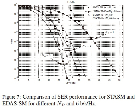
Once again, STASM outperforms EDAS-SM for Nr ≤2. For example, at an SER of 10-8, the SNR gain yielded for Nr = 1 and Nr = 2 is 18 dB and 4 dB, respectively. For Nr= 3, similar behavior as demonstrated in Figure 6 is evident. Returning to the case of Nr= 3, and once again noting the diversity order of STASM and EDAS-SM as d1= NrNt[13] and d2 = Nr (Nt - Nsm + 1) [19], respectively, it is clear that the slope of STASM will always be greater than that of EDAS-SM, since Nsm > 1. This implies a cross-over point between the SER curves of STASM and EDAS-SM, whenever the latter is superior in the low-to-medium SNR regime. For the case of 4 b/s/Hz and 6 b/s/Hz, in Figure 8, we have extended the range of SNRs plotted to demonstrate the cross-over points between the SER curves of STASM and EDAS-SM. For 4 b/s/Hz, until approximately 19 dB, EDAS-SM is superior; however, beyond the cross-over point, STASM is superior. For 6 b/s/Hz, the same behavior is demonstrated, i.e. STASM begins to outperform EDAS-SM after the cross-over point at approximately 24.8 dB. The investigations clearly demonstrate that STASM is substantially superior for Nr = 1 at low-to-high SNRs. Although STASM achieves full-diversity (NtNr) compared to EDAS-SM (Nr (Nt- Nsm + 1)) the cross-over point for Nr > 1 usually occurs in the moderate-to-high SNR region. In the interest of energy efficiency, operation at these SNRs may not be practical, hence EDAS-SM would be the superior choice. Thus, depending on the number of receive antennas employed, EDAS-SM may be superior to STASM for practical SNRs. With reliability in mind, and based on the above comparisons, we are motivated to propose an adaptive scheme, which employs transmit mode switching between STASM and EDAS-SM. The objective of the proposed scheme is to minimize error performance by switching between STASM and EDAS-SM, the transmission candidates. The criterion proposed for selecting the transmission mode is the ISEP. This is primarily motivated by the fact that the ISEP can be largely computed by employing a look-up-table (LUT) approach, hence limiting the CC imposed.
As a note, in terms of CC (considering floating point operations (flops) [10]), the STASM scheme only requires the computation of ||hj||F, j Є[1 : Nt]. This imposes Nt(2Nr- 1) flops only; which, is negligible compared to that of EDAS-SM [9].
4.2 System Model of the Proposed Scheme
Consider a MIMO communication system with NT transmit antennas, NRreceive antennas and a perfect feedback link to the transmitter, as depicted in Figure 9. Transmission is based on selection between two candidate transmission modes, viz. STASM and EDAS-SM, each independently operating as discussed in Section 2. Note, as explained earlier, we consider M-QAM. At the receiver, the corresponding detection unit is employed such as to extract the message. Furthermore, an important function at the receiver is the transmission candidate selector. In this module, based on CSIR, the candidate transmission modes are considered, such as to satisfy a target spectral efficiency defined as ßsTASM = log2M b/s/Hz or ßEDAs-SM = log2NSMM b/s/Hz for STASM and EDAS-SM, respectively.

Assuming a slowly varying channel and CSIR, the ISEP for each of the candidate transmission modes is computed, and the transmission mode is chosen such that the ISEP is minimized.
In the next two subsections, we analyze the ISEP for each of the candidate transmission modes in the proposed scheme.
4.3 ISEP for STASM
Considering M-QAM, the ISEP may be defined as:

4.4 ISEP for EDAS-SM
The derivation of the ISEP for EDAS-SM follows the method of [20]. On this note, the ISEP of EDAS-SM for transmit antenna k, k Є [1 : NSM], can be formulated as  where
where  is the ISEP of transmit antenna index error and
  is the ISEP for M-QAM (note this is the lower bound, since we assume the probabilities
  and
and  are independent [20]). Expressions for
  and
and  may be derived as follows:
Given that the M-QAM transmit symbol is detected at the receiver without errors, the upper bound for  can be formulated as follows [21, pp. 261-262]:

where  is the conditional PEP of choosing
  given that xkq was transmitted. The conditional PEP can be formulated as follows:
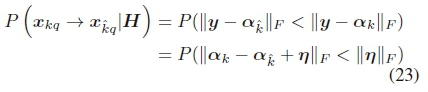
where 
Employing the triangle inequality, (23) can be written as:

But  , where the w-th element of n is given as
  . As earlier, I and Q represent the in-phase and quadrature parts of a complex number.
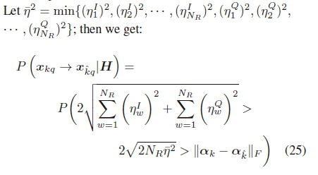
Finally, with some manipulation and use of the Q-function it may be verified that (25) can be written as:

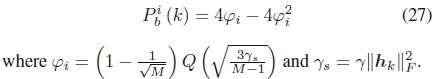
where fj is an AWGN random variable with zero mean and variance 0.5.
For M-QAM, PI (k) is approximately given by [14, (45)],
In the next subsection, we present an example algorithm of the proposed adaptive scheme employing a target spectral efficiency of ßSTASM= ßEDAS-SM= 4 b/s/Hz.
4.5 Example Algorithm for 4 b/s/Hz
In this subsection, an example algorithm for a target spectral efficiency of ßsTASM = Pedas-sm= 4 b/s/Hz is presented. The configuration of NT= 6 and NR= 3 is assumed. To satisfy the target spectral efficiency of 4 b/s/Hz, the candidate transmission modes are set as follows: a) STASM - NT= 6, 16-QAM, b) EDAS-SM -NT =6, NsM =4, 4-QAM. The example algorithm for selection of the transmission mode proceeds as follows:
Step 1: Construct the following 3 x 6 matrix at the receiver:

Step 2: Find  , such that
 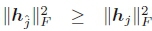 ,
,  .
.
Step 3: Compute ISEP for STASM based on (21).
Step 4: Determine all enumerations of NSM = 4 transmit antennas, where the total number of enumerations is given by  .
.
Step 5: Determine the enumeration lthat maximizes the MED, such that the (i, j)-th element of D, Di,jfor i = j is computed as:

and for i = j, Di,jis given as:

where R is a 4 x 4 upper-triangular matrix having zero entries at the locations (1,2) and (3,4).
The enumeration lselected is then defined as:

Step 6: Compute the ISEP for EDAS-SM using (22) and (26). Hence, the overall ISEP is computed as:

where each  , takes each of the possible transmit antennas into account.
At this stage, the ISEP for STASM and EDAS-SM have been computed. Finally, the transmission mode is chosen based on the minimum ISEP and the transmitter is notified of the chosen mode via the feedback link (refer to Figure 9).
4.6 Analysis of CC
In this subsection, the CC of the proposed adaptive transmit mode switching scheme is analyzed in terms of flops, similar to [10].
Steps 1 and 4 do not impose any flops. Step 2 involves 2(NR- 1)NT flops. In Step 3,  has already been computed. Hence, only 5 flops are required and a LUT can be used for computation of the Q-function and square-root operations. Step 5 involves the selection of the enumeration of NSM transmit antennas and since
 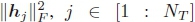 , has been already computed, imposes only 64
  flops [9]. Finally, Step 6 may also employ the LUT for computation of the Q-function and square-root operations. Hence, it may be validated that NSM(11 + 3NR) - 2 flops are imposed. Therefore, the overall imposed CC is given by
  flops.
4.7 Numerical Results
In this subsection, we evaluate the average SER versus SNR for the proposed adaptive system and draw comparison between the CC for the adaptive scheme and its closed-loop counterparts, i.e. EDAS-SM and STASM. We consider a Rayleigh frequency-flat fading channel and complete knowledge thereof at the receiver. The Monte Carlo simulation results for a spectral efficiencies of 4 b/s/Hz and 6 b/s/Hz are presented in Figures 10 and 11, respectively, for Nr = 1, 2 and 3. In the case of 4 b/s/Hz, for Nr = 1, the error performance of the proposed system matches STASM, which was superior across the SNR range. For Nr = 2, up until 10 dB, the SER of both EDAS-SM and STASM are identical, after which the cross-over point manifests and STASM is superior. The proposed scheme follows STASM in this region of SNRs. The proposed scheme completely follows EDAS-SM for NR= 3.

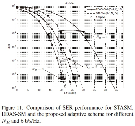
For a spectral efficiency of 6 b/s/Hz, identical behavior is demonstrated (refer to Figure 11) for NR= 1. Considering NR= 2, which clearly shows how STASM outperforms EDAS-SM after the cross-over point, it is demonstrated that the proposed adaptive system follows the minimum error performance curve of STASM/EDAS-SM. In the case of NR= 3, the proposed adaptive scheme completely follows EDAS-SM. Hence, the proposed scheme exploits the advantages of both EDAS-SM and STASM, such as to improve reliability.
Table 1 tabulates the CC for the adaptive scheme compared to EDAS-SM and STASM. We consider 4 b/s/Hz and 6 b/s/Hz, similar to Figure 10 and 11. The CC of EDAS-SM is given in [10, Section III.B]. As expected, it is evident that the adaptive scheme imposes a slightly larger CC compared to EDAS-SM and is at worst-case 16% larger for NR= 1, while providing an SNR gain of more than 10 dB. For NR = 2 and NR= 3, the worst-case increase is 5%.

5. CONCLUSION
In this paper, closed-form expressions for the ASEP of STASM with M-QAM and M-PSK were presented.
The formulated ASEP expressions were relatively easy to evaluate and further validated the Monte Carlo simulation results. Comparisons have been drawn with EDAS-SM. STASM achieves full-diversity compared to EDAS-SM; however, the cross-over point may occur in the moderate-to-high SNR region. Hence, an adaptive system with two candidate transmission modes (STASM/EDAS-SM) was proposed and investigated; the error performance was minimized across the SNR range.
REFERENCES
[1] R. Mesleh, H. Haas, C.W. Ahn, S. Yun, "Spatial Modulation - A New Low Complexity Spectral Efficiency Enhancing Technique," in Proceedings of the Conference on Communications and Networking in China, Oct. 2006.
[2] J. Jeganathan, A. Ghrayeb, L. Szczecinski, "Spatial Modulation: Optimal Detection and Performance Analysis," IEEE Communications Letters, vol. 12, no. 8, pp. 545-547, Aug. 2008. [ Links ]
[3] P. Yang, M.D. Renzo, Y. Xiao, S. Li, L. Hanzo, "Design Guidelines for Spatial Modulation," IEEE Communication Surveys and Tutorials, vol. 17, no. 1, pp. 6-26, Jan.-Mar. 2015. [ Links ]
[4] M.D. Renzo, H. Haas, A. Ghrayeb, S. Sugiura, L. Hanzo, "Spatial Modulation for Generalized MIMO: Challenges, Opportunities, and Implementation," Proceedings of the IEEE, vol. 102, no. 1, pp. 56-103, Jan. 2014. [ Links ]
[5] P. Yang, Y. Xiao, Y. Yu, S. Li, "Adaptive Spatial Modulation for Wireless MIMO Transmission Systems," IEEE Communications Letters, vol. 15, no. 6, pp. 602-604, Jun. 2011. [ Links ]
[6] P. Yang, Y. Xiao, L. Li, Q. Tang, Y. Yu, S. Li, "Link Adaption for Spatial Modulation with Limited Feedback," IEEE Transactions on Vehicular Technology, vol. 61, no. 8, pp. 3808-3813, Oct. 2012. [ Links ]
[7] R. Rajashekar, K.V.S. Hari, L. Hanzo, "Antenna Selection in Spatial Modulation Systems," IEEE Communications Letters, vol. 17, no. 3, pp. 521-524, Mar. 2013. [ Links ]
[8] N. Pillay, H. Xu, "Comments on "Antenna Selection in Spatial Modulation Systems"," IEEE Communications Letters, vol. 17, no. 9, pp. 1681-1683, Sep. 2013. [ Links ]
[9] N. Wang, W. Liu, H. Men, M. Jin, H. Xu, "Further Complexity Reduction using Rotational Symmetry for EDAS in Spatial Modulation," IEEE Communications Letters, vol. 18, no. 10, pp. 1835-1838, Oct. 2014. [ Links ]
[10] K. Ntontin, M.D. Renzo, A.I. Perez-Neira, C. Verikoukis, "A Low-Complexity Method for Antenna Selection in Spatial Modulation Systems," IEEE Communications Letters, vol. 17, no. 12, pp. 2312-2315, Dec. 2013. [ Links ]
[11] S. Thoen, L. Van der Perre, B. Gyselinckx, M. Engels, "Performance Analysis of Combined Transmit-SC/Receive MRC," IEEE Transactions on Communications, vol. 49, no. 1, pp. 5-8, Jan. 2001. [ Links ]
[12] Z. Chen, "Asymptotic Performance of Transmit Antenna Selection with Maximal Ratio Combining for Generalized Selection Criterion," IEEE Communication Letters, vol. 8, no. 4, pp. 247-249, Apr. 2004. [ Links ]
[13] Z. Chen, J. Yuan, B. Vucetic, "Analysis of Transmit Antenna Selection/Maximal-Ratio Combining in Rayleigh Fading Channels," IEEE Transactions on Vehicular Technology, vol. 54, no. 4, pp. 1312-1321, Jul. 2005. [ Links ]
[14] M.K. Simon, M-S. Alouini, "A Unified Approach to the Performance Analysis of Digital Communication over Generalized Fading Channels," Proceedings of the IEEE, vol. 86, no. 9, pp. 1860-1877, Sep. 1998. [ Links ]
[15] R. Merris, "Combinatorics," John Wiley and Sons, New Jersey, USA, 2003.
[16] A. Goldsmith, "Wireless Communications," Cambridge University Press, California, USA, 2005.
[17] A. Annamalai, C. Tellambura, "An MGF-Derivative based Unified Analysis of Incoherent Diversity Reception of M-ary Orthogonal Signals over Fading Channels," in Proceedings IEEE 54-th Vehicular Technology Conference, pp. 2404-2408, Oct. 2001.
[18] A. Annamalai, C. Tellambura, "Error Rates for Nakagami-m Fading Multichannel Reception of Binary and M-ary Signals," vol. 49, no. 1, pp. 58-68, Jan. 2001.
[19] R. Rajashekar, K.V.S. Hari, L. Hanzo, "Quantifying the Transmit Diversity Order of Euclidean Distance Based Antenna Selection in Spatial Modulation," IEEE Signal Processing Letters, vol. 22, no. 9, pp. 1434-1437, Sep. 2015. [ Links ]
[20] N.R. Naidoo, H.J. Xu, T.A. Quazi, "Spatial modulation: optimal detector asymptotic performance and multiple-stage detection," IET Communications, vol. 5, no. 10, pp. 1368-1376, 2011. [ Links ]
[21] J.G. Proakis, "Digital Communications," McGraw-Hill, New York, USA, 2001.

