Serviços Personalizados
Artigo
 Inglês (pdf)
 Artigo em XML
 Referências do artigo
Indicadores

Links relacionados
-
 Citado por Google
 -
 Similares em Google
Compartilhar

 Permalink
SAIEE Africa Research Journal
versão On-line ISSN 1991-1696
versão impressa ISSN 0038-2221
SAIEE ARJ vol.109 no.4 Observatory, Johannesburg Dez. 2018
ARTICLES
Instantaneous bit error rate based ASM scheme for MPSK spatial modulation
Tarika Balmahoon*; Hongjun Xu**
University of Kwa Zulu-Natal, Dept. of Electrical, Electronic and Computer Engineering, Durban, 4041, Republic of South Africa
ABSTRACT
In this paper, we propose an instantaneous bit error rate (IBER) based adaptive spatial modulation (ASM) scheme for the M-ary phase shift keying (MPSK) constellation (ASM-MPSK). In the proposed ASM-MPSK system, the combination of MPSK modulation order and number of transmit antennas is chosen based on the one that yields the smallest IBER while keeping the average transmission bit rate (TBR) constant. Furthermore, a low complexity maximum likelihood (ML) detection scheme for MPSK SM is employed which significantly reduces the complexity of the proposed system compared with other adaptive modulation schemes that use the high complexity ML detector for detection. Additionally, in this paper, we also analyse the computational complexity for the proposed ASM-MPSK. The simulation results indicate that the proposed scheme provides a significant improvement in terms of the error performance compared to conventional MPSK SM systems under a particular TBR; for TBR = 5 bits/s/Hz, a performance gain of approximately 4 dB had been achieved at a BER of 1 X 10⁻⁶.
Keywords: Adaptive spatial modulation, bit error rate, MIMO, MPSK modulation.
1. INTRODUCTION
Multiple-input multiple-output (MIMO) has been considered as one of the core techniques for improving data throughput, link reliability and spectral efficiency [1]. For example, Wi-Fi and Long Term Evolution (LTE) are using the MIMO wireless technology because of its advantages. However, one main drawback of MIMO communications is the increase in detection complexity and the cost of implementation compared to single-input single-output (SISO) systems. This is mainly due to the requirement of synchronization between the antennas, the strong inter-channel interference (ICI) between each of the receive antennas and multiple radio frequency (RF) chains [2]. Spatial modulation (SM) is a special MIMO scheme that has been proposed by Mesleh et al. [3]. This scheme has only one active transmit antenna during data transmission, therefore, ICI is completely eliminated and the decoding complexity at the receiver is reduced. It is therefore a strong candidate for next generation wireless communications [4]. The attractiveness of SM has lead researchers to explore techniques for enhancing system error performance and/or spectral efficiency. In order to achieve this, various closed-loop schemes have been considered. These schemes can be broadly classified into transmit antenna selection [5, 6] and adaptive modulation [7, 9, 10].
One of the closed-loop schemes is transmit antenna selection. Rajashekar et al. [5] proposed an attractive Euclidean distance based transmit antenna selection (EDAS) for MQAM SM to improve error performance. This algorithm is based on the construction of an Euclidean distance element matrix and its subsequent QR decomposition. The bit error rate (BER) performance of this scheme had been compared to the conventional SM scheme and a significant improvement had been obtained with the new scheme. Then, in [6], the authors presented a reduced-complexity EDAS for MPSK and MQAM constellations. This was achieved by exploiting the symmetry properties of the MPSK and MQAM constellations thereby further enhancing the system performance.
Another closed-loop scheme is adaptive modulation. Adaptive modulation can be used to improve either throughput or error performance. In terms of improving throughput the authors in [7] proposed an adaptive MQAM SM scheme. Average theoretical BER bounds are derived based on the received SNR. Then, the adaptive MQAM SM switching levels are determined in order to maximize the throughput while meeting the average target BER. These switching levels are numerically estimated based on the approach in [8] for each average SNR value that maximizes average throughput. In terms of improving error performance Yang et al. [9] proposed a low complexity adaptive modulation scheme for SM systems (LC-ASM). This scheme is based on the approach in [10], where the pairwise error probability (PEP) for MIMO V-BLAST maximum likelihood (ML) systems is improved by maximizing the received minimum distance of the transmit symbol vectors. But, it was found that this scheme has the problem of data inconsistency. This is because the authors in [9] did not consider that for SM systems the transmit antenna also carries information when transmitting data. Therefore, if the index of the transmit antenna is detected erroneously, the length of detected data is different from the length of the transmitted data. This results in data inconsistency in the adaptive SM in [9].
Motivated by the data inconsistency error in [9], we present an ASM scheme for MPSK SM (ASM-MPSK) in order to improve the BER of the conventional SM system. Firstly, we present the closed form instantaneous bit error rate (IBER) expression for MPSK SM and then use this as the metric in the proposed ASM-MPSK scheme. The IBER is a more accurate metric than the nearest neighbour approximation used in [9, Eq.4], since it takes into account both the bit error rate of symbol estimation as well as the bit error rate of antenna index estimation. In [9]-[10], the authors used the ML detector in [11] for detection. Although this detector provides optimal results, the computational complexity is very high. In this paper, we use the low complexity ML detection algorithm for MPSK SM (LC-ML) proposed by Men et al. [2]. This detection algorithm provides optimal results and the computational complexity is independent of M. Many classic detectors have been well designed for arbitrary constellations, such as QAM and PSK. For instance, the low complexity sub optimal signal vector based detector had been proposed in [12] for both MQAM and MPSK constellations has a computational complexity that is independent of the modulation order M. However, the MPSK low complexity ML detector in [2] had been used because, to the best of the authors knowledge, it is the only optimal detector that has a computational complexity independent of the modulation order M. The choice of using only an optimal detector was made so that the best possible results can be obtained. We then analyse the computational complexity of the proposed scheme.
The remainder of this paper is as follows: in Section 2, a system model of the proposed ASM-MPSK scheme is presented. Section 3 contains the derivation of the closed form IBER expression for MPSK SM and a discussion of the proposed ASM-MPSK scheme. The complexity analysis of the proposed scheme is given in Section 4. In Section 5 the simulation results are shown and an example of the proposed ASM-MPSK scheme is presented. Lastly, the paper is concluded in Section 6.
Notation: Lowercase letters that have bold and italic font represent vectors. Uppercase letters that have bold and italic font represent matrices. Regular letters represent scalar quantities. ( - )T, ||-||F and E[-]are the transpose, Frobenius norm and Euclidean norm, respectively. argmaxw(-) and min(-) represents the argument of the maximum with respect to w and the minimum value of the argument, respectively. Lastly,  ( - ) and
  ( - ) represents the real and imaginary parts of a complex argument, respectively.
The proposed NTOTAL x NR ASM-MPSK system model with an example of transmission bit rate (TBR) of 6 bits/s/Hz is shown in Fig. 1, where NTOTAL = 16 is the total number of available transmit antennas and NR is the number of receive antennas. In contrast to the conventional SM systems, which use the same modulation order and fixed bits to select the transmit antenna, the proposed ASM scheme uses different modulation orders and dynamic bits to select the transmit antenna. The selected modulation order M and a number of transmit antennas NT are chosen by the switching unit, where M ≥ 4 and NT = 2K ≤ NTOTAL, K Є Z, respectively. The switching unit in Fig. 1 consists of all possible combinations of MPSK modulation orders and number of transmit antennas that have a TBR of 6 bits/s/Hz. For convenience we define a combination of MPSK modulation orders and number of transmit antennas as a transmission candidate. Note that the ASM-MPSK system in Fig. 1 uses the conventional MPSK modulation and MPSK SM for NT = 1 and NT > 1, respectively. As the channel varies, the adaptive unit at the receiver selects a candidate for transmission and sends this information to the transmitter through a feedback link. The transmitter then employs the corresponding modulation order and the number of transmit antennas for the next channel use.

The SM mapper output in Fig. 1 above can be expressed as xjq = [0 0... xq ... 0]T, where xjq is the NT dimensional signal vector, j is the selected transmitted antenna index, xq denotes the qth symbol from the MPSK constellation with E[|x4|2] = 1 and q Є [1:M]. All symbols are contained in symbol set s. The received signal у can be expressed as,
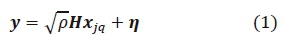
where у = [y1, y2 , . . . -УNR] , p is the average signal-to-noise ratio (SNR) at each of the receive antennas, H = [h1h2... hNT] is an NR x NT channel matrix and ր is an NR x 1 additive white Gaussian noise (AWGN) vector. Both H and ր have independent and identically distributed entries according to the complex Gaussian distribution CN (0,1).
We also assume that the channel state information (CSI) is perfectly known at the receiver. In [9] and [10], the authors have also assumed perfect CSI at the receiver. However, in practical scenarios, the channel estimation using pilot/training symbols is prone to errors and degradation [13]. Rajashekar et al. [13] analyzed the performance of antenna selection algorithms in SM systems with imperfect CSI at the receiver. However, this is beyond the scope of the paper. The LC-ML detector for MPSK in [2] is used for detection in this paper. This contributes to a reduction in computational complexity of the proposed system compared with other adaptive SM schemes [7, 9, 10] that use the ML detection method in [11] for detection.
3. PROPOSED ADAPTIVE SPATIAL MODULATION FOR MPSK
The proposed ASM-MPSK system is based on finding the smallest IBER amongst all transmission candidates under a particular TBR. Generally, the number of candidates for a specific TBR is given by (TBR - 1) in the proposed NT0TAL x NRASM-MPSK system for M ≥ 4. Considering a 4 X NRASM-MPSK system as an example, we have TBR = 4 bits/s/Hz. The 4xNr ASM-MPSK system has 3 possible transmission candidates:1) 1X NR16PSK modulation with transmit antenna selection; 2) 2 x NR 8PSK SM with transmit antenna selection, and 3) 4x NR 4PSK SM without transmit antenna selection. The transmit antenna(s) of candidate 1 and 2 in the above example are chosen through antenna selection techniques which will be explicitly explained in Subsection 3.1 of this section. In the proposed ASM-MPSK scheme, the candidate that has the smallest IBER will be chosen for transmission under the given channel condition.
In this section, we firstly discuss the techniques that were used to perform the transmit antenna selection. Secondly, we present the IBER for each transmission candidate. This is used as the metric to determine which ASM candidate is selected for transmission. Finally, we explain the transmission candidate selection algorithm for the proposed ASM-MPSK scheme.
3.1 Transmit antenna selection techniques
In the proposed ASM-MPSK system, one of transmission candidates is 1 x NRMPSK modulation. In this transmission, one out of NT0TALtransmit antennas is selected based on the largest channel gain. The largest channel gain is obtained by evaluating
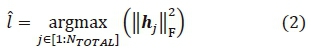
where the arg max operator selects the largest element ||Hj||2F .
The rest of the transmission candidates are NT X NRASM-MPSK SM for 1 < NT≤ NT0TAL. The low complexity Euclidean distance based antenna selection (LC-EDAS) in [6] is used to select NTout of NT0TALtransmit antennas. For the scheme in [6], the rotational symmetry property of the MPSK constellation is exploited in order to reduce the complexity of other existing EDAS scheme [5]. This low complexity EDAS scheme selects two or more transmit antennas based on the EDAS criterion which is the maximization of the minimum instantaneous Euclidean distance among all possible SM symbols [3]. The algorithm is based on the construction of an Euclidean-distance element matrix and its subsequent QR decomposition. The LC-EDAS algorithm is summarized below;
1. Determine  , which is the set of enumerations of all possible (
 ) combinations of selecting NT out of NT0TALtransmit antennas. Let L be the set that contains all
  .
.
2. Factorize the modified channel matrix using QR decomposition.
3. Construct NT0TAL X NT0TALEuclidean distance element matrix, D. The (i,j)thelements of D, where i  j, are given by,

and xq2 represent symbols from the MPSK symbol set and I and Q are the in-phase (real) and quadrature (imaginary) components of the MPSK signal constellation set s, respectively. Note that only one MPSK constellation point is required in order to calculate Di,j above. The diagonal elements are given by 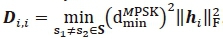 , where hi is the channel vector corresponding to the ith transmit antenna and
  represents the minimum distance between any two symbols in s.
4. Determine NT x NT sub-matrices of D(L), by deleting all rows and columns of D that are absent in L
5. The antenna set that that maximizes the minimum Euclidean distance is given by,

In (3), LED contains the indices  which are the NT selected transmit antenna indices.
3.2 Theoretical instantaneous BER for MPSK SM
The spatial modulation detector is responsible for the estimation of two quantities: the active transmit antenna and transmitted symbol. As a result, SM error performance depends on the error rates of these two processes. For the following analysis we consider these two processes and assume that the transmit antenna and symbol estimation processes are independent [14].
Given fading channels, the IBER for conventional MPSK, is given by [14],

where, ys is the instantaneous SNR per MPSK symbol and m = log2M is the total number of bits per MPSK symbol [15].
Now, we consider the overall IBER for each transmission candidate in the proposed ASM-MPSK system.
For 1 x NRMPSK modulation the overall IBER, is given by,

where Îis the selected transmit antenna index from (2). For NT x NRASM-MPSK modulation, the overall IBER is given by [16],

In (6), Pb is the average IBER of the transmit symbol estimation given that the transmit antenna index is perfectly detected and is given by,
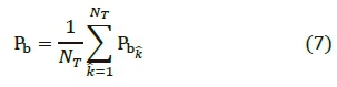
where  are the NT selected transmit antenna indices from (3) and
  is given in (4).
In (6), Pa is the bit error probability of transmit antenna index estimation given that the symbol is perfectly detected and is given by [Eq. 19, 1].
3.3 Proposed IBER based ASM algorithm
The proposed ASM-MPSK is based on IBER which has been derived in Subsection 3.1. Fig. 2 below illustrates the algorithm for the proposed ASM scheme. Each time the channel varies, the procedure in Fig. 2 is carried out.
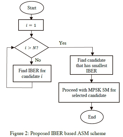
In Fig. 2 above, N is the total number of candidates for a particular TBR. The IBER is computed for each candidate and the candidate having the lowest IBER is selected for transmission. Thereafter, we proceed with MPSK SM using M and NT as specified by the selected candidate.
4. EVALUATION AND COMPARISON OF THE AVERAGE ERROR PERFORMANCE
In this section, we present the simulation results for the proposed ASM-MPSK scheme for a TBR of 3, 4 and 5 bits/s/Hz. In all instances, we assume that the CSI is known at the receiver. For all results shown in this paper, a quasi-static Rayleigh flat-fading channel is employed. Note that all achievable SNR gains due to the proposed MPSK-ASM scheme are measured at a BER value of 10-6 with respect to the 4PSK SM transmission candidate where NT = NTOTAL. The theoretical analysis for this candidate is also included in the simulation result for 3, 4 and 5 bits/s/Hz in order to verify the MPSK SM simulation results. For all results shown in this section, we employ the LC- ML detector [2]. In order to denote the antenna configuration and modulation order used for the simulation results, we use the following notation: (NT, NR, M).
For the simulation results in Fig. 3 below we have used an ASM-MPSK system having a TBR of 3 bits/s/Hz. There are 2 possible candidates for this system: 1 x 4 conventional 8PSK and 2x4 4PSK SM. In Fig. 3 below we compare the ASM result achieved to the 4PSK SM transmission candidate.

It is evident from Fig. 3 above that there is a considerable improvement in BER of the proposed ASM-MPSK scheme compared to the MPSK SM candidate; At a BER value of 10-6 there is a 1.2 dB improvement.
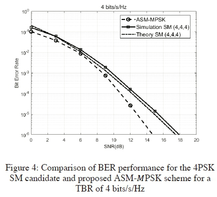
For the next simulation results in Fig. 4 below, we have used an ASM-MPSK system having a TBR of 4 bits/s/Hz. The possible SM candidates for this system are: 2x4 8PSK SM with transmit antenna selection, 4x4 4PSK SM without transmit antenna selection and conventional 1x4 16PSK modulation with transmit antenna selection. In Fig. 4 below, the ASM-MPSK result for the proposed scheme is compared with candidate 2 which is the 4PSK SM system, Once again, we notice from Fig. 4 above that there is a significant improvement in the BER of the proposed ASM-MPSK scheme compared to the 4x4 4PSK SM candidate; at a BER value of 10-6, a 2.2 dB improvement is achieved with the proposed scheme.
Finally, for the simulation result in Fig. 5 below we have used an ASM-MPSK system having a TBR of 5 bits/s/Hz. There are 4 possible candidates for this system: conventional 1 x 4 8PSK with transmit antenna selection, 8x4 4PSK SM without transmit antenna selection, 4x4 8PSK SM with transmit antenna selection and 2x 4 16PSK SM with transmit antenna selection. In Fig. 5 below we compare the ASM-MPSK result achieved to the 8x4 4PSK SM candidate.
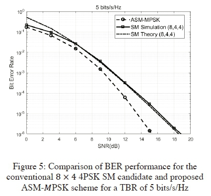
It is evident from Fig. 5 above that there is a substantial improvement in the BER of the proposed ASM-MPSK scheme compared to the 8x4 4PSK SM candidate; At a BER value of 10-6 a 3.8 dB gain is achieved with the proposed scheme.
In Table 1 below, we summarize the achievable SNR gain due to the proposed MPSK-ASM scheme at a BER of 10-6 for a TBR of 3, 4 and 5 bits/s/Hz. For each TBR, these gains are with respect to the SM candidate that has NT = NTOTAL and M = 4. Table 1 also shows that the SNR gain achieved by the system increases as the number of transmit antennas increase.

5. COMPLEXITY ANALYSIS
In this section, the computational complexity of the proposed ASM-MPSK scheme is analyzed by exploiting the concept of the computational complexity in [5]. It is defined as the total number of real and complex-valued operations. (Addition, subtraction, division and multiplication are counted as one operation). The proposed ASM-MPSK scheme contains the EDAS and LC-ML algorithms. The computational complexity for both the EDAS and LC-ML algorithms have been considered in [5] and [2] respectively. Using this, we derive the computational complexity for the proposed ASM-MPSK scheme. Also, in this section an example is given to show the computational complexity and IBER of the proposed ASM scheme under a particular channel condition.
5.1 Computational complexity analysis for proposed ASM-MPSK scheme
PB in (4) needs to be calculated for each candidate under a particular TBR. We first compute yS in (5) . This requires NR - 1 addition operations and 2 multiplication operations. Since, (5) only needs to be computed for one candidate under a particular TBR, the total number of operations required is NR + 1. Then, in (7), we are required to calculate Ys for the remaining N - 1 candidates. This requires a total of (N - 1)(NT(NR + 1)) operations.
Next, we need determine the number of operations required for evaluating the Q function in (4). In order to do this, we consider the Q function in terms of the complementary error function and error function. Let 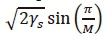 . Then,
 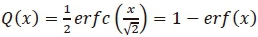 , [EQ.A.17,17]. Thereafter, we solve
  for the unit point x. We evaluate erf(x) using the trapezoidal rule in [17] for a unit point. This is given by
  . Now we can obtain the Q function approximation by evaluating 1 - erf(x). Thus, the evaluation of the Q function for a unit point requires 1 and 3 subtraction and multiplication operation/s respectively. Since the Q function needs to be computed for each candidate NT times, we require a total 4NNT operations [15]. In order to evaluate the rest of (5) and (7), we require 1 and 2NT multiplication operation/s respectively.
Now, we consider the computational complexity involved in calculating Pa in [Eq.19, 1]. The notation ua in [Eq.19, 1] is defined as,  where
where  is the variance of the channel distribution and is given by
  =
=  . This will be broken down into two parts: Firstly,
  , which is the pairwise error probability (PEP) of choosing signal vector
  given that Xjq was transmitted. Secondly,
  which is the number of bits in error between transmit antenna index j and estimated tranmsit antenna index j. The PEP requires 7 operations for calculating ua ,1 operation for and 2 operations for [1 - ua]2. Since the calculation of uainvolves finding the variance, in [Eq.19, 1], for each of the symbols in the symbol set, the search space is M. For the term,
  , of the PEP expression, we assume that wis NR - 1 so that we only consider the maximum possible complexity for the term. We evaluate the expression as follows:
  which requires 2NR - 3 operations for the numerator term and 2NR - 2 operations for each of the denominator term. Since there is one division operation in the expression, the total number of operations for the PEP expression is M(4NR - 5). Then, for the term in [Eq.19, 1], we simply consider the bit errors between j and
  one at a time, where j and
  are all possible combinations of transmit antenna index and estimated transmit antenna index respectively. Note that is not equal to j. Therefore, the complexity for this term is the search space NTNT. The denominator of [Eq.19, 1]. requires 2 operations. Note that Pais only computed for N - 1 candidates, where 1 < NT ≤ NT0TAL. Thus, the total number of operations required to calculate Pafor a given TBR is N - 1(M(4NR + 5)+ NTNT).
Next, we consider the transmit antenna selection that is required for the conventional MPSK and MPSK SM candidates. For the case where NT = 1, we use the antenna selection technique in (2). We require NT(NR - 1) addition operations and NTmultiplication operations in order to evaluate (2). Thus the total computational complexity required for this technique is NTNT(NR - 1). For the case where 1 < NT≤ NT0TAL, we use the LC-EDAS technique described in Section 3 of the paper. The computational complexity for this technique is given in [6] as  . Note that this needs to be computed for N - 1 candidates under a particular TBR.
Lastly, the computational complexity for the LC-ML detection algorithm has been derived in [2] and is given as NT(6NR + 9). Whereas the high complexity ML detection algorithm used in [5,9,10] has a complexity of 6NRNTM[2].
Thus, the number of operations required for one iteration of the proposed algorithm as shown in Fig. 2 is given below by  where NT = 1 and
  where 1 < NT≤ N TOTAL;

Therefore, the total number of operations required is given by,

In Table 2 below, we compute the computational complexity for a system having NT = 2 and NR = 2 for various transmission bit rates. Note we are considering only one iteration as shown in Fig. 2.

The computational complexity of the proposed scheme is compared to LC-ASM scheme in [9] where the exact values of the number of complex operations had been given for a system with a TBR of 3 bits/s/Hz. The computational complexity in [9] had not been derived. Only the total number of complex-valued operations had been given. Therefore, we consider only the complex-valued operations of the proposed scheme for this operation. This is given by,

It is evident that when considering only complex-valued operation for a system with TBR of 3 bits/s/Hz, the proposed ASM- PSK scheme achieves an improvement of 62.8% in computational complexity when compared to the ASM scheme in [9]. Therefore, the proposed algorithm has the advantage of complexity reduction and good performance.
5.2 Example
Consider an SM system with NR= 4 and TBR 4 bits/s/Hz. The TBR - 1 possible candidates are;
1) Ntotal = 4 NT=2 M =8
2) NT = 4 M = 4
3) NT0TAL = 4 NT = 1 M = 16
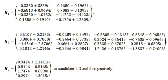
Fig. 6 below shows the IBER and corresponding computational complexity, Sproposed in (11) of the three transmission candidates for the 4/bits/s/Hz transmission system. The channel gain matrix for this example is given in the Appendix.
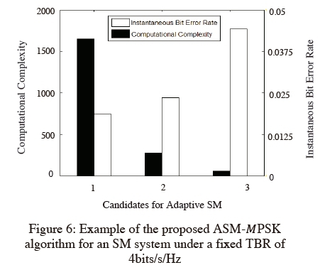
Since candidate 1 in Fig. 6 above possesses the lowest IBER, it will be the chosen candidate for transmission.
6. CONCLUSION
In this paper, we have proposed a simple ASM- PSK algorithm for PSK constellations in order to obtain better system performance under a target TBR. The optimum candidate for transmission is determined based on the one that yields the smallest IBER performance. As the channel varies, the adaptive unit at the receiver computes the optimum candidate for transmission and sends this information to the transmitter through a low-bandwidth feedback path. The computational complexity for the proposed scheme has been analyzed and it is evident that the proposed scheme has the advantage of reduced computational complexity compared with existing ASM schemes. Simulation results show that the proposed scheme has considerable performance improvement in terms of the BER, especially at high SNR, compared to the conventional SM system.
REFERENCES
[1] N. R. Naidoo, H. J. Xu and T. Al Mumit Quazi, "Spatial modulation: Optimal detector asymptotic performance and multiple-stage detection," IET Communications Journal, vol. 5, no. 10, pp. 13681376, July 2011. [ Links ]
[2] H. Men and M. Jin, "A Low-Complexity ML Detection Algorithm for Spatial Modulation Systems With MPSK Constellation," IEEE Communications Letter, vol. 18, no. 8, pp. 13751378, June 2014. [ Links ]
[3] R. Mesleh, H. Haas, C. W. Ahn and S. Yun, "Spatial Modulation - A New Low Complexity Spectral Efficiency Enhancing Technique," in First International Conference on Communications and Networking in China, 2006. ChinaCom06., Beijing, China, 2006.
[4] P. Yang, Y. Xiao, L. Li, Q. Tang, Y. Yu and S. Li, "Link Adaptation for Spatial Modulation With Limited Feedback," IEEE Transaction on Vehicular Technology, vol. 61, no. 8, pp. 3808-3813, July 2012. [ Links ]
[5] R. Rajashekar, K. Hari and L. Hanzo, "Antenna Selection in Spatial Modulation Systems," IEEE Communications Letter, vol. 17, no. 3, pp. 521-524, January 2013. [ Links ]
[6] N. Wang, W. Liu, H. Men, M. Jin and H. Xu, "Further Complexity Reduction Using Rotational Symmetry for EDAS in Spatial Modulation," IEEE Communications Letter, vol. 18, no. 10, pp. 18351838, August 2014. [ Links ]
[7] B. M. Mthethwa and H. Xu, "Adaptive M-ary quadrature amplitude spatial modulation," IET Communications, vol. 6, no. 18, pp. 3098-3108, December 2012. [ Links ]
[8] Q. Liu, S. Zhou and G. Giannaakis, "Queing wih adaptve modulation and coding over wireless links: cross layer analysis and design," IEEE Transactions on Wireless Communications , vol. 4, no. 3, pp. 1142-1153, May 2005. [ Links ]
[9] P. Yang, Y. Xiao, Y. Yu and S. Li, "Adaptive Spatial Modulation for Wireless MIMO Transmission Systems," IEEE Communications Letter, vol. 15, no. 6, pp. 602-604, 2011. [ Links ]
[10] J. Ham, M.-S. Kim, C. Lee and T. Hwang, "An Adaptive Modulation Algorithm for Perfromance Improvement of MIMO ML Systems," IEEE Communications Letter, vol. 12, no. 11, pp. 819-821, 2008. [ Links ]
[11] J. Jeganathan, A. Ghrayeb and L. Szczecinski, "Spatial Modulation: Optimal Detection and Perfrormance Analysis," IEEE Communications Letter, vol. 12, no. 8, pp. 545-547, 2008. [ Links ]
[12] W. Jintao, J. Shuyun and S. Jian, "Signal Vector Based Detection Scheme for Spatial Modulation," IEEE Communications Letters, vol. 16, no. 1, pp. 1921, 2012. [ Links ]
[13] R. Rajashekar, K. Hari, K. Giridhar and L. Hanzo, "Performance Analysis of Antenna Selection Algorithms in Spatial Modulation Systems with Imperfect CSIR," in European Wireless 2013; 19th European Wireless Conference, Guildford, UK, 2013.
[14] W. J. Craig, "A new, simple and exact result for calculating the probablity of error for two-dimensional signal constellations," in IEEE Military Communications Conference,1991. MILCOM91, Conference Record, Military Communications in a Changing World, Mc Lean, VA, USA, 1991.
[15] T. Balmahoon and H. Xu, "Low-complexity EDAS and low-complexity detection scheme for MPSK spatial modulation," IET Communications, vol. 10, no. 14, pp. 1752 - 1757, 2016. [ Links ]
[16] N. R. Naidoo, H. J. Xu and T. A.-M. Quazi, "Spatial Modulation: Optimal Detector Asymptotic Performance and Multiple-Stage Detection," Institution of Engineering and Technology Communications, vol. 5, no. 10, pp. 1368 - 1376, July 2011. [ Links ]
[17] M. S. Gockenbach, Understanding and Implementing the Finite Element Method, Philadelphia, 2006.
* E-mail: tarika.balmahoon@gmail.com
** E-mail: xuh@ukzn.ac.za
The channel gain matrix H, for the example in Subsection 5.2 is given by,