


Services on Demand
Article
 English (pdf)
 Article in xml format
 Article references
Indicators

Related links
-
 Cited by Google
 -
 Similars in Google
Share

 Permalink
SAIEE Africa Research Journal
On-line version ISSN 1991-1696
Print version ISSN 0038-2221
SAIEE ARJ vol.108 n.1 Observatory, Johannesburg Mar. 2017
Design and optimisation of a PCB eddy current displacement sensor
A.J. GroblerI; G. van SchoorII; E.O. RanftI
ISchool of Electrical, Electronic and Computer Engineering, North-West University, Potchefstroom, South Africa, e-mail: andre.grobler@nwu.ac.za
IIUnit for Energy and Technology Systems, North-West University, Potchefstroom, South Africa
ABSTRACT
Position sensing is one of the crucial parts of many systems, specifically in an active magnetic bearing. The position is used to control the magnetic forces within an active magnetic bearing to keep a rotor levitated. Sensors used in these systems must be very sensitive and are usually very expensive. In this paper a low cost printed circuit board position sensor is analysed. The sensor uses an excitation coil to establish a magnetic field. Four sensing coils are then used to measure the influence a conducting target has on the magnetic field to enable position sensing. The sensor's magnetic operation is analysed using finite element methods and very good correlation is found with measured results. The effects of the target material and the number of PCB layers are analysed. It is shown that a two layer sensor can produce acceptable sensitivity and linearity.
Key words: eddy current, displacement sensor, multiple layer PCB
1. INTRODUCTION
IN active magnetic bearings (AMB) systems accurate position sensing of the levitated object, mostly a rotating rotor, is essential. Due to its impact both in terms of cost and reliability, position sensing in AMB systems is an important research topic. Two currently prominent approaches to determining the rotor position are self-sensing and dedicated non-contact sensors. In self sensing, the rotor position is approximated using the change in actuator inductance, caused by rotor movement [1, 2]. Dedicated position sensor technologies used n AMBs, include; optical, inductive, eddy current, Hall-effect and capacitive types [3]. AMB systems have very small airgaps between the rotor and stator, usually around 0.5 mm. The rotor can thus only move 0.25 mm in the radial direction before making contact with the backup bearings.
Eddy current sensors induce eddy currents in a conducting arget and uses the change in magnetic field due to the eddy currents to measure various physical parameters. A single coil can be used as the excitation and measuring coil in which case the change in inductance is usually detected through the change in oscillation frequency of the excitation circuit. Sensing coils are not connected to the excitation coil and a change in induced voltage can be measured using analog to digital converters. These sensors are commonly used to measure lateral displacement [4], otation [5] and axial displacement [6]. It is also used to detect defects in materials like PCBs [7] and is highly dependent on material properties [8]. These sensors have also been used in condition monitoring, for example measuring turbine rotor vibrations [9], [10]. Various applications require that flexible PCBs be used to reach in small spaces [11]. Vyroubal has developed transformer equivalent circuits for the probes [12] as well as improving the driving circuitry [13].
Philipp Bühler registered a patent in 2002 [14] for a device to measure a rotor position in multiple directions. In 2004, Larsonneur and Bühler presented a printed circuit board (PCB) sensor, based on the aforementioned patent, for measuring radial movement of the rotor in an AMB system [15]. This concept was also used to develop a sensor for high temperature AMBs, using thick-film manufacturing techniques [16]. Larsonneur and Bühler reported that modelling of the sensor should be explored further as "model predictions do not yet satisfyingly agree with measurement results" [15]. The contribution of this article is showing a two-dimensional finite element method (FEM) model can accurately predict the sensor's output for movement perpendicular to the sensing coil.
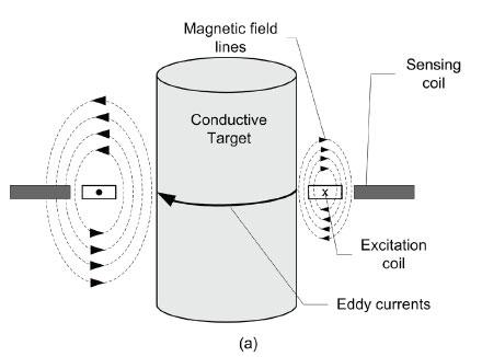
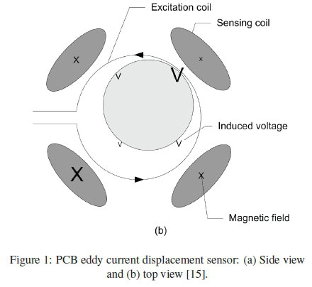
The probe of this sensor comprises an excitation coil and four sensing coils; all planar coils formed using PCB tracks. Figure 1(a) and (b) illustrate the sensor arrangement through a side and top view respectively. A high frequency sinusoidal current (1-10 MHz) is applied to the excitation coil, thus establishing a varying magnetic field around it. The four sensing coils are placed around the excitation coil, each covering about a quarter of the circumference of the target. Placing a conductive target inside the excitation coil causes eddy currents to flow in the target. When the target is moved relative to the probe, magnetic field coupling to the sensing coils will be influenced by the eddy currents flowing in the target. When the target is close to a sensing coil, the magnetic field coupling with the sensing coil will be decreased by the eddy currents. Similarly a larger magnetic field coupling with the sensing coil located far from the target will prevail.
As explained above, the target should be electrically conductive for an eddy current sensing principle to be used. The penetration depth (δ) of the magnetic fields can be calculated using
where f is the frequency of the excitation current, σ is the permeability and σ is the conductivity of the target. Aluminium is commonly used as target for eddy current sensors and has a calculated penetration depth of 58.5 μηι if a 2 MHz signal is used. Stainless steel, for example SAE 304, is also widely used in AMB rotors since it has a high yield strength and does not influence the AMB's magnetic field as it is non-magnetic. The penetration depth of SAE 304 at 2 MHz is calculated as 302 μηι. If a magnetic material is used as the target the penetration depth will be significantly smaller. Mild steel has a calculated penetration depth of less than 10 μΓα In the AMB environment the position sensing is usaually done on a non-magnetic surface. As the position sensor's target on the rotor is placed very close to the AMB, a magnetic target will introduce hytesteresis losses if a heteropolar radial AMB is used.
This article presents a FEM model for a PCB sensor in Section 2. The model is verified using a purpose built test platform as discussed in Section 3. In Section 4 the optimal sensor configuration is analysed to deterimine the impact some paramenters has on performance.
2. MODELLING
Deriving an accurate model for the PCB sensor can help the designer understand the influence a certain parameter has on the operation and performance of the sensor. A model can be used to ensure specifications are met when designing a sensor. A model can perdict the behavior of the sensor in various conditions and operating modes.
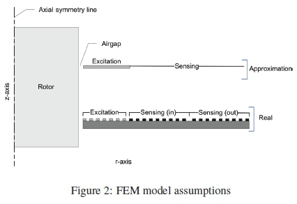
The computational resources needed to solve a FEM model are influenced by the number of nodes in the model. If the three-dimensional reality has a symmetry axis, a two-dimensional approximation can be made without decreasing the accuracy of the model. Figure 2 shows the two-dimensional approximation of the PCB sensor. The excitation and sensing coils will be realised with tracks on a PCB as shown in the lower part of the figure. In an approximation in the upper part of Figure 2, the excitation coils are modeled as a rectangle with the same dimensions of the tracks and half the current density, thus incorperating the voids between the tracks. The sensing coil is approximated with a line, since only the magnetic flux passing through this line will be used further to calculate the induced voltage. This model is implemented in COMSOL Multiphasics® using the axial symmetry Quasi-Statics Azimuthal Currents application mode.
The sensing coils' voltages are the main model output. A coil voltage (e) can be determined using Faraday's law, shown in (2), if the change in magnetic flux (ΔΦ) through the sensing coil, number of turns on the coil (N) and period of the excitation current (Δ), are known.
The magnetic flux can be determined using (3), where B is the magnetic field density and A the sensing coil area.
Sensitivity and linearity are two of the performance parameters used when optimising the sensor. Sensitivity (S) is the ratio of voltage change (ΔV) and displacement (Δx), see (4). Linearity gives an indication of how close the calibration curve fits a straight line. The maximum deviation above and below the straight line, Vmt and VMB, and the total displacement (Δx), are used to determine linearity, as given by (5).
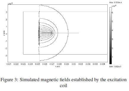
Figure 3 shows the magnetic fields established by the excitation coil and passing through the sensing coils. The magnetic fields passing through the target induces eddy currents in the target. Figure 4 shows the modelled peak voltage induced in a sensing coil when a target is moved between 0.25 mm and 0.75 mm from the PCB. The results for three different materials (SAE 304 stainless steel, copper and aluminium) are shown. The conductance (σ) and permeability (μ) of the target influences the eddy currents flowing in the target and thus the amplitude of the voltage induced in the sensing coil. Copper is the most conductive, thus a smaller voltage is induced when compared to stainless steel that is less conductive.
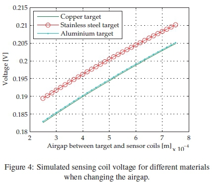
The simulation results shown in Figure 4 support the sensor operation described previously. There is a sufficient change in voltage to warrant manufacturing a prototype sensor. This prototype will be used to verify the model presented in this section.
3. MODEL VERIFICATION
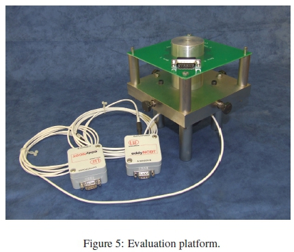
3.1 Evaluation platform
To verify the FEM model, a sensor was designed using the model and constructed using standard PCB manufacturing techniques. An evaluation platform was also developed as is shown in Figure 5. The reference position was measured by two eddyNCDT 3701 sensors from MICRO-EPSILON® on an aluminium target. These sensors can measure on any conductive material but were calibrated on aluminium. These sensors have a measuring range of 1 mm, linearity of 6 % full scale output (FSO), < 0.001 % FSO repeatability, < 0.000033 % FSO static resolution and < 0.00016 % FSO dynamic resolution. In the test setup, movement is always parallel with a coil pair (e.g. coils 1 and 3) and perpendicular with the other coil pair (e.g. coils 2 and 4).
3.2 Comparing simulation and measured results
This section compares the simulation results to the measured results. The voltage on a sensing coil was recoded for 10 μs (or 20 cycles), sampled at 2.5 GHz using the LeCroy® WaveRunner® 6030A digital oscilloscope. Ten data sets were recorded and the amplitude of the fundamental frequency determined using fast Fourier transform in MATLAB. The median of these 10 values represents a data point, referred to as measured voltage.
Figures 6 and 7 show the voltage measured on the four sensing coils of the single layer sensor when moving the aluminium target from sensing coil 4 towards sensing coil 2 as well as moving from sensing coil 1 towards sensing coil 3. This movement causes an increase in the airgap between sensing coil 4 (1) and the target. As a result the voltage measured on sensing coil 4(1) and 2 (3) decreases and increases, respectively. Due to the symmetry in the model, the model results for sensing coil 2 (3) have the same but negative gradient and the values but will decrease as the airgap increase, labled "Simulation decrease" in Figure 6. The sensing coils are numbered 1 - 4 in a clockwise rotation, starting at the coil just right of the connector.
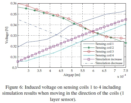
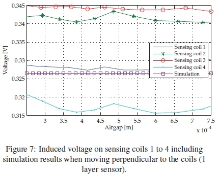
There is a dc offset in all measurements compared to the model results. This can be attributed to voltage induced in the connection track of the sensing coils by the excitation coil magnetic field. The voltages measured across sensing coils remain constant when the target does not move relative to these coils. Again there is some dc offset and the voltages measured on sensing coils 3 and 2 are larger as these have longer connection tracks.
Differential measurements of opposite coils will be used when implementing the sensor as this will reduce the influence of common mode effects like temperature and magnetic interference. The sensitivity is also doubled. Differential measurements were taken for the 2-layer sensor, moving an aluminium target between sensing coil 1 and 3. Figure 8 shows the differential results. Sensing coils 1 and 3 results closely agree with that predicted by the model.
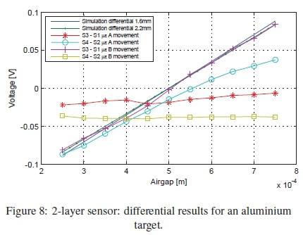
Table 1 compares the sensitivity results for 2 different target materials when the single-layer sensor is used. The results when using aluminium (Al) and stainless steel (Ss) targets show good correlation between modelled and measured results.
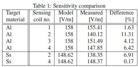
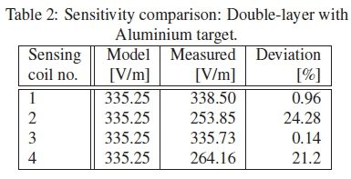
Table 2 shows the results for the double-layer sensor when an aluminium target is used. The results of the two sensing coil pairs (1&3,2&4) are not the same. Sensing coils 1 and 3 measured results correlate well with the modelled results. Sensing coils 2 and 4 results do not show good correlation with the model. The next section will discuss a possible cause for the difference in results.
3.3 Oscillator circuit drift
The excitation current was created using a voltage-to-current circuit and a bench signal generator (EZ® Digital FG7020A), together called the oscillator circuit. In this section the change of the measured sensing coil voltage over time is investigated. Figure 9 shows the rms voltage measured on a sensing coil against a number of measurements. The target is not moved and no changes are made to the test setup. The voltage was measured using a LeCroy® WaveRunner® 6030A digital oscilloscope. Measurements 1 to 24 are taken after the oscillator circuit operated for a long time (> 7 hours), measurements 25 to 53 were taken 10 minutes after switching on the oscillator circuit and measurements 54 to 78 are taken 1 hour after switching on the oscillator circuit. At the start of each measuring series the oscillator voltage is adjusted to ensure a 100 mA rms current is flowing in the excitation coil. Each of the measurement series is taken over a 6 minute time frame in 15 second intervals.
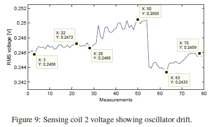
When the circuit was active for a long time (measurements 1 to 24) there is not a significant change in the voltage. But when considering the large change when just switching on the circuit and when adjusting as at measurement 54, it is clear that the oscillator circuit has a significant influence on the measurements. Considering the small change in voltage (around 40 mV for the single layer) when moving the target through the whole range, the measurements shown in Figure 9 could easily cause a 10 % error as seen in Table 1. The large deviation in sensing coils 2 and 4 seen in Table 2 when moving in the sensing coil 2 direction could thus be caused by oscillator circuit drift.
Note that there are also other differences when comparing the experimental setup to the simulation results. Sensing coils 2 and 3 have longer tracks from the connecter to the coil that sensing coils 1 and 4. It was found that the difference can be as big as 100 mV, thus accounting for the dc offsets seen in Figures 6 and 7. But these differences remained the same, regardless of the target movement and would thus not influence the sensor's sensitivity.
4. OPTIMISATION CONSIDERATIONS
This section presents some of the considerations to design an optimal sensor using the model presented in the previous section. Table 3 lists the optimisation criteria and variables that can be modified to optimise the sensor performance as well as some of the paramenters assumed to be constant.
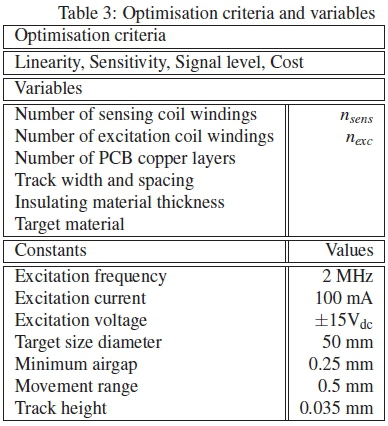
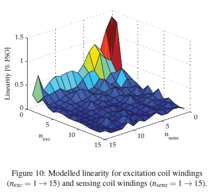
Linearity is the least crucial performance parameter since the position signal can be linearised by applying a function fit to the calibration curve. Figure 10 shows the modelled linearity (in percentage of full scale output (FSO) of a single sensor when varying the number of excitation coil windings (nexc) and the number of sensing coil windings (nsens). An exponential decrease in linearity can be seen when increasing either variables. All of the combinations where nexc > 5 and nsens > 5 have a linearity smaller than 0.3 % FSO, an acceptable value for the sensor.
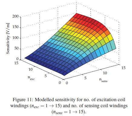
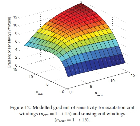
The modelled sensitivity for different combinations of nexc and nsens are shown in Figure 11. Increasing nsens causes an increase in sensitivity. When increasing nexc, sensitivity also increases but reaches a turning point, clearly seen when nsens = 15 and nexc = 1 - 15. According to this figure, nsensshould be as large as possible and nexcshould be chosen on a turning point, when designing an optimal sensor. More insight can be gained by considering the gradient of the sensitivity when varying nsensand nexc, as shown in Figure 12. From this figure it is clear that for a certain nsens, a maximum gradient of sensitivity can be found by varying nexc.
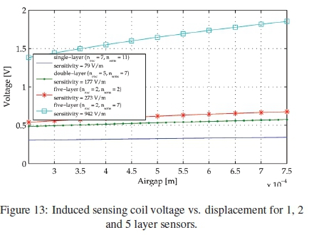
The number of layers the PCB sensor is implemented on can also be varied to optimise the sensor's sensitivity and signal level. A high signal level is beneficial when the noise effects between the sensor and demodulation circuitry must be minimised. The conductors connecting the sensing coils and the demodulation circuitry will, in some cases, be long and routed in noisy environments. Figure 13 shows the voltage induced on a sensing coil when varying the airgap, for a single-, double- and five-layer sensor configuration. The signal level and sensitivity increase with an increase in number of PCB layers. Unfortunately, the cost of manufacturing the PCB also increases when the number of PCB layers increase. A five-layer sensor costs ten times more to manufacture than a single-layer sensor. It was found that a double-layer sensor is the best option when considering cost and sensitivity.
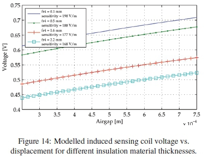
The conductive layers of a PCB are placed on an insulating material (fr4). The effect of varying this thickness must also be investigated. Figure 14 shows the induced voltage vs. airgap for four fr4 thicknesses: 0.1, 0.5, 1.6 and 2.2 mm. The standard fr4 thickness is 1.6 mm, thus this figure represents the whole range of commonly found fr4 thicknesses. A small improvement in sensitivity and signal level is found when using a thinner insulation layer. This can be attributed to an increase in the magnetic coupling between the excitation and sensing coils located on the different layers. A thinner insulation material is more fragile and expensive to manufacture, and the performance improvement is not significant when compared to other variables.
The influence of changing the copper track width and spacing is the final variables explored in this article. Figure 15 shows the induced sensing coil voltage when adjusting the airgap, for different combinations of excitation and sensing coil's track spacing and width. The signal level is significantly higher when a narrower excitation coil track width and spacing is used. In this situation, the same magnetic flux is generated by a physical smaller coil thus more of the magnetic flux couples to the sensing coil, inducing an larger voltage in it. The sensing coil's track spacing and width does not significantly influence the signal level.
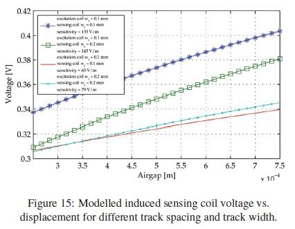
Sensitivity is increased when using a narrower excitation coil track and spacing. In this situation, the sensing coils are located close to the target, thus more sensitive for target movement. The sensitivity is marginally increased when increasing the sensor coil's track width and spacing.
5. CONCLUSION
This article presented a low cost, eddy current displacement sensor. The sensor unit can be produced very cheaply by using PCBs to realise the sensor coils. The sensor is designed to use in AMBs and was tested on a representative rotor diameter. The number of excitation and sensing coil turns that will result in an optimal sensitivity and linearity have been identified using FEM simulations. The FEM model was verified using an evaluation platform where MICRO-EPSILON® eddy current sensors were used as reference. Aluminium, stainless steel and mild steel targets were used and good correlation achieved for the first two.
The use of multi-layer PCBs was also investigated. Increasing the number of layers led to a significant increase in sensitivity. This came at a significant increase in manufacturing cost. It is thus proposed that a standard thickness FR4, double layer PCB be used with 0.2 mm tracks and spacing be used. The sensor can then be manufactured for less than 2 % of the cost of eddy current sensors usually used in AMB systems. Note that the drive electronics, amplification and signal processing required to give an position output have not been included in the cost as these components are still being developed.
Future work will include futher modelling and characterisation to assess the viability of the concept. This includes 3D FEM modelling to establish the linearity of the final sensing results in the 2 principal directions. This will also involve signal processing using all four sensing signals. Finally the electromagnetic compatibility of the sensor in an actual AMB system with all possible electromagnetic disturbances should be investigated.
REFERENCES
[1] E. O. Ranft, G. van Schoor, and C. P. du Rand, "An integrated self-sensing approach for active magnetic bearings," SAIEE African Research Journal, vol. 4, pp. 90-97,2011. [ Links ]
[2] G. van Schoor, A. Niemann, and C. du Rand, "Evaluation of demodulation algorithms for robust self-sensing active magnetic bearings," Sensors and Actuators A: Physical, vol. 189, no. 0, pp. 441 - 450, 2013. [ Links ]
[3] G. Schweitzer, H. Bleuler, and A. Traxler, Active magnetic bearings : Basics, Properties and Applications of Active magnetic bearings. Zurich: Authors Working Group, 2003.
[4] L. Weiwen, Z. Hui, and Q. Hongli, "Research on novel grating eddy-current absolute-position sensor," Instrumentation and Measurement, IEEE Transactions on, vol. 58, no. 10, pp. 3678-3683, Oct 2009. [ Links ]
[5] A. Wogersien, S. Samson, J. Guttler, S. Beiftner, and S. Biittgenbach, "Novel inductive eddy current sensor for angle measurement," in Sensors, 2003. Proceedings of IEEE, vol. 1, Oct 2003, pp. 236-241 Vol.1.
[6] P. Wang, Z. Fu, and T. Ding, "A frameless eddy current sensor for cryogenic displacement measurement," Sensors and Actuators A: Physical, vol. 159, no. 1, pp. 7 - 11, 2010. [ Links ]
[7] K. Chomsuwan, S. Yamada, and M. Iwahara, "Bare PCB inspection system with SV-GMR sensor eddy-current testing probe," Sensors Journal, IEEE, vol. 7, no. 5, pp. 890-896, May 2007. [ Links ]
[8] G. Y. Tian, Z. X. Zhao, and R. W. Baines, "The research of inhomogeneity in eddy current sensor," Sensors and Actuators, vol. A 69, pp. 148-151,1998. [ Links ]
[9] J. Wilde and Y. Lai, "Design optimization of an eddy current sensor using the finite-elements method," Microelectronics Reliability, vol. 43, no. 3, pp. 345 - 349, 2003. [ Links ]
[10] M. Tsutomu, G. Sho, D. Kenta, K. Yoshinori, A. Yuichi, E. Shigemi, and S. Hiroki, "Method for identifying type of eddy-current displacement sensor," Magnetics, IEEE Transactions on, vol. 47, no. 10, pp. 3554-3557, Oct 2011. [ Links ]
[11] X. Chen and T. Ding, "Flexible eddy current sensor array for proximity sensing," Sensors and Actuators A: Physical, vol. 135, no. 1, pp. 126 - 130, 2007. [ Links ]
[12] D. Vyroubal, "Impedance of the eddy-current displacement probe: The transformer model," IEEE Transactions on instrumentation and measurement, vol. 53, no. 2, pp. 384-391, April 2004. [ Links ]
[13] -, "Eddy-current displacement transducer with extended linear range and automatic tuning," Instrumentation and Measurement, IEEE Transactions on, vol. 58, no. 9, pp. 3221-3231, Sept 2009. [ Links ]
[14] P. Bühler, "Device for cantact-less measurement of distances in multiple directions," Europe Patent 1422492, May 26, 2004.
[15] R. Larsonneur and P. Bühler, "New radial sensor for active magnetic bearings," in International Symposium on Magnetic Bearings, no. 9, Lexington, Kentucky, USA, August 2004.
[16] L. Burdet, T. Maeder, R. Siegwart, P. Buhler, and B. Aeschlimann, "Thick-film radial position sensor for high temperature active magnetic bearings," in Symposium on Magnetic Bearings, no. 10, Marigny, Switzerland, August 2006.

