


Serviços Personalizados
Artigo
 Inglês (pdf)
 Artigo em XML
 Referências do artigo
Indicadores

Links relacionados
-
 Citado por Google
 -
 Similares em Google
Compartilhar

 Permalink
Water SA
versão On-line ISSN 1816-7950
versão impressa ISSN 0378-4738
Water SA vol.49 no.1 Pretoria Jan. 2023
http://dx.doi.org/10.17159/wsa/2023.v49.i1.3982
RESEARCH PAPER
Forward osmosis treatment of thermal evaporator brine stream
EN SitabuleI, II; C BuckleyII, †
ISasol Research & Technology, Sasolburg 1947, South Africa
IIWASH R&D Centre, School of Engineering, University of KwaZulu-Natal, Durban 4041, South Africa
†deceased
ABSTRACT
Forward osmosis technology was evaluated for treating evaporator brine stream from a petrochemical industry at bench scale using ammonium bicarbonate as a draw solution. Calcium carbonate scaling that forms from the interaction between the calcium ions in the feed solution and carbonate ions from the draw solution (reverse salt diffusion) leads to the reduction in water flux and water recoveries achievable (feed TDS concentration of -60 000 mg-L-1, calcium -545 mg-L-1 and draw solution (ammonium bicarbonate) concentration of-240 000 mg-L-1). Fouling can be prevented by softening the feedwater before it is treated in forward osmosis. Without calcium and magnesium, permeate fluxes and water recoveries of up to 6L m-2·h-1 and 60%, respectively, could be achieved. It was also observed in this study that the concentration of the calcium ions in the feed does have an impact on the formation of the calcium carbonate scale, implying that some hardness can be tolerated in the feed to the forward osmosis process. It can, therefore, be concluded that without some hardness removal, ammonium bicarbonate draw solution is not suitable for treating concentrated brine streams (e.g., evaporator brine) that contain a high concentration of calcium ions. FO technology using ammonium bicarbonate as a draw solution can be considered an alternative technology to treat concentrated brine streams from inland industries, provided some pre-treatment to remove scaling precursors such as calcium is incorporated in the flow scheme.
Keywords: scaling, softening, ammonium bicarbonate, forward osmosis, membrane fouling, reverse salt flux,brine, draw solution
INTRODUCTION
Desalination processes such as reverse osmosis, thermal evaporators, ion exchange, and electro dialysis produce brine streams that require additional handling and disposal in a sustainable manner (Nathoo, livanji, and Lewis, 2009). For landlocked plants, a serious challenge is posed, as ocean disposal of brine is not available as an option. As a result, effective brine minimization technologies towards achieving zero liquid effluent discharge (ZLED) are required to reduce water treatment costs and environmental impact. Brine management for inland industries includes discharge to the surface, deep well injection, land disposal or treatment through reverse osmosis (RO), electro dialysis reversal (EDR), evaporation ponds, and thermal evaporation (Morillo et al., 2014; Muftah, 2011). Brine disposal to evaporation ponds holds the danger of ground and surface water contamination. Treatment of brines using RO and EDR generates large quantities of brines as water recovery in these processes is restricted by scaling, fouling, and salinity of the water (Watson, Morin, and Henthorne, 2003). Mechanical/thermal evaporation technologies for brine treatment are costly and energy-intensive, and scaling of heat exchanger tubes is a big challenge that could result in further energy use due to cleaning requirements (Goh et al., 2017). Deep well injection is an attractive option for disposing of brines, but this option is not always available (Morillo et al., 2014; Muftah, 2011).
Due to the limitations of the existing membrane and thermal desalination technologies briefly discussed above, alternative technologies are required to improve water recovery. To achieve ZLED, or near-ZLED, thermal desalination technologies (e.g., evaporators, crystallizers) are traditionally considered, due to their ability to treat brines to a slurry or final product that is easy to handle or sell while achieving water recoveries up to 99%. Despite these benefits, these technologies are both CapEx (capital expense) and OpEx (operational expense) intensive due to equipment and energy costs, respectively (Morillo et al., 2014; Semiat, 2008; Watson et al., 2003). The high cost of brine treatment/management, together with strict environmental legislation (pending Waste Discharge Charges System (National Water Act: RSA, 1998)), provides an incentive to find new technologies to treat brines from inland industries.
Forward osmosis (FO) has emerged as a potential technology that could further concentrate brines and subsequently reduce the cost of brine disposal. FO technology has been identified as having potential incremental and breakthrough opportunities for brine treatment/desalination options. The attractiveness of the FO process revolves around its low potential power consumption and high water recovery. Unlike other membrane desalination technologies, this technology relies on the osmotic pressure differential between the concentrated draw solution and lower concentration feedwater (i.e., RO brines, seawater) to draw the water through the semipermeable membrane using the osmotic pressure driving force. During this process, a diluted draw solution is produced, and further treatment is required to recover the draw solution; in the process, clean water is produced. The energy consumption for forward osmosis technologies cited in the literature ranges from 0.8-13 kWh m-3 compared to that of the thermal brine concentrators ranging from 19-27 kWh-m-3. A rough comparison of the specific investment cost (SIC), calculated as the investment cost divided by the capacity for water production, among the different membrane-based brine technologies and thermal-based processes showed that membrane-based processes (including FO) have lower investment costs, at below 2 000 USD-m~3-d-1 compared with 1 800-4 400 USD-m-3 d-1 for the brine concentrator (salt concentration from the limit of SWRO to around 200 000 mg4L-1) (Backer et al., 2022; Tsai et al., 2017).
The forward osmosis process requires a minimal external energy input, mainly for liquidcirculation and draw solution regeneration. The low energy requirement provides an opportunity of using thermal energy from waste heat or renewables in cases where a volatile draw solution is used (Zhao et al., 2012). The forward osmosis process does not require exotic materials (e.g., titanium, duplex stainless steel) and high-pressure tubing and, as a result, the capital cost of the system is low. Also, as a result of low, or no, hydraulic pressure applied, forward osmosis will have a low propensity for fouling (compared to competing membrane and thermal systems) which will reduce the capital and operating cost of the plant. In the forward osmosis process, feedwater can be concentrated to higher salinity levels than RO, resulting in higher salinity feedwater applications and competing with conventional thermal evaporative systems for concentrated feedwater. The lower brine volume generated from higher water recoveries results in reduced size of the final disposal system, such as a crystallizer.
A major limitation of the FO process is the lack of enhanced and reliable specifically designed membranes. Water transport through the FO membrane is limited by several phenomena, namely, internal concentration polarization, external concentration polarization, fouling, and reverse salt diffusion (Zhao et al., 2012). Commercially available FO membranes are low flux, resulting in large membrane areas for treatment, leading to increased capital costs. Another major drawback with forward osmosis has been the unavailability of effective draw solutions for using FO for high-salinity reject brine treatment. A wide variety of draw solutions have been studied, and along with membrane development, this area continues to be a research focus.
In this study, the technical feasibility of treating a high-salinity stream from the thermal evaporator using forward osmosis technology was evaluated at bench scale.
MATERIAL AND METHODS
Experimental set-up
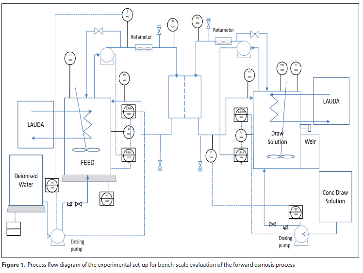
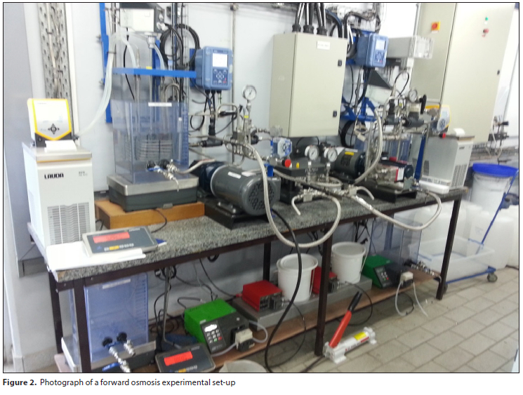
A bench-scale test FO system was designed and built for this study. Figures 1 and 2 show a process flow diagram and a photograph of the bench-scale experimental FO set-up utilized in this study.
The FO membrane cell system was designed to simulate the concentration of various brine streams at constant draw solution concentration. The tanks (feed, draw solution, and concentrated draw solution tanks) are filled with relevant fluids before the operation of the equipment.
The FO membrane cell (stainless steel) (Sterlitech Corporation, Kent, USA) was constructed to have symmetric flow channels or chambers on both sides of the membrane which enable both the feed solution and draw solution (DS) to flow tangentially across the installed membrane. The active membrane surface area is 140 cm2. Spacers (0.79 mm) placed in the feed and the DS channels were used to support the membrane and enhance the mixing of the DS and feed solution.
Two 15 L Perspex tanks were constructed, which were used to hold the feed (operating volume was 8 L) and the draw solution. A Hydra-Cell positive displacement pump (Warner Engineering) fitted with a variable speed drive motor was used to circulate the feed and draw solutions between their respective feed tanks and the FO membrane cell. The feed and draw solution flow rates were measured using a flow meter installed on the suction side of the feed and draw solution pumps, respectively. Coiled stainless steel tube heat exchangers were installed in both the feed and draw solution tanks, and the temperature in these tanks was controlled to a selected temperature using Lauda baths (Eco Silver-ECO 415). Feed and draw solution conductivities were measured using K = 1 cm 1 and K = 10 cm 1 cell constant probes (Knick), respectively. Level switches installed in the feed tank and draw solution tank were used to control the levels in these tanks. Peristaltic pumps mounted on the feed and draw solution side of the membrane cell were used to manage the concentration of the feed and draw solution by dosing deionized (DI) water and 4 M concentrated draw solution, respectively. 15 L Perspex tanks held the DI water and the concentrated draw solution. The DI water tank was placed on the analytical balance (Sartorius SIWRDCP-1-15-L from Taratec) connected to the DELTA V system to monitor the water flux through the membrane. This analytical balance was used when a constant feed and constant draw solution philosophy was simulated (discussed in detail below). In this study, this balance was not used, as the volume of water lost to the draw solution tank was very low when compared to the starting volume, and also the change in feed water conductivity was too low to alter the osmotic pressure differential. A similar analytical balance was used to monitor the mass of water permeating through the membrane from the feed tank to the draw solution tank from which water flux was calculated. Stirrers were used to keep the feed and draw solutions homogeneous. ASPEN Process Explorers 2006.5-Aspen One software was used to record the DELTA V data.
Potential ammonia losses from ammonium bicarbonate solutions were managed by conducting the experiments at a maximum temperature of 30°C and covering the tanks.
Feed and draw solutions
Feed solutions
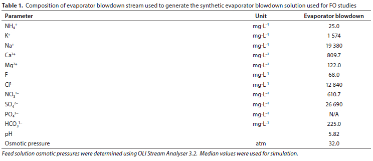
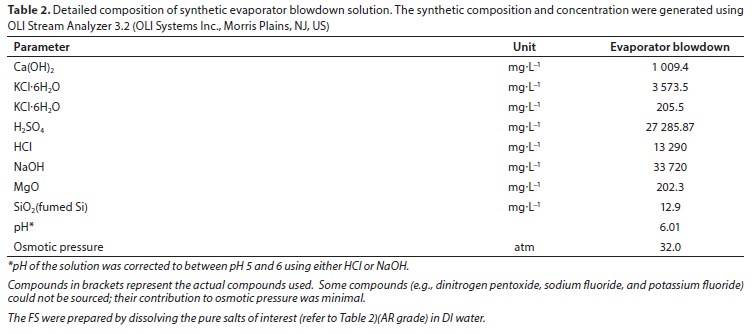
Synthetic evaporator blowdown was used as feed solution (FS) to evaluate the forward osmosis process. OLI Stream Analyzer software was used to simulate synthetic evaporator blowdown solutions using chemical compositions of actual evaporator blowdown shown in Table 1.
Deionized water was used as the FS for membrane characterization with respect to pure water flux and reverse salt flux before the baseline and synthetic runs were undertaken.
Sodium chloride was used as FS to simulate water fluxes and recovery behaviours without membrane scaling or fouling (baseline run) for the stream of interest (evaporator blowdown). The NaCl solutions were prepared so that they have the same osmotic pressure as the synthetic solutions (Table 1).
Sodium chloride solution (AR) was used for baseline experiments. Baseline experiments were conducted to evaluate the impact of osmotic pressure differential on flux. The concentration of sodium chloride used for baseline experiments was 40 g-L-1 with an osmotic pressure of 32 atm (3 242 kPa).
Table 2 shows a detailed composition of OLI model synthetic solutions (compounds simulated using OLI software and molecular output (apparent species)) used to simulate the actual streams in Table 1.
Draw solution
All experiments were conducted using 3 M ammonium bicarbonate as the draw solution. Gentle heat was needed for the complete dissolution of the salt. The temperature did not exceed 30°C. As the mode of operation for these experiments was based on a constant draw solution concentration, a concentrated ammonium bicarbonate solution (4 M) was used to correct the conductivity of the draw solution to a set conductivity value. This was important to ensure that the change in water flux was not influenced by osmotic dilution. Evaluation of the regeneration of the draw solution was not part of the scope of this study
Membranes tested
A commercially available FO-TFC membrane (Hydration Technology Innovations - HTI) was used for all the experiments. This membrane was previously compared with the FO-CTA membrane, and the results showed that an FO-TFC membrane water flux in both membrane orientations was consistently higher than that for the FO-CTA membrane (Sitabule, 2021). Furthermore, the FO-TFC membrane has a high pH tolerance in a 2-11 pH range. The FO-CTA membrane is inappropriate for alkaline pH applications due to its limited pH tolerance (3-8). An ammonium bicarbonate draw solution (alkaline pH) was used in this study, and the FO-TFC membrane is preferred as there will not be any pH correction required. Virgin membrane coupons were cut to FO cell size and stored in distilled water overnight before use in each experiment. Each experiment comprised of: pure water flux, non-scaling NaCl run simulating a particular stream osmotic pressure and scaling run using a synthetic analogue of a particular stream.
Experimental conditions
All pure water flux experiments (experiments for characterizing the membrane with respect to water flux and reverse salt flux using DI as feed water) using 3 M ammonium bicarbonate as a draw solution were conducted for a 2 h period. The runs for the actual experiments using NaCl or synthetic streams were conducted until 70% (equipment limitation) of water was recovered or until significant fouling was experienced or until a reduction in osmotic pressure differential, which resulted in an insignificant change in water flux.
The cross-flow rate of the feed and draw solutions was 1.5 L-min-1 (equivalent to 33.3 cm-s-1 cross-flow velocity). All the experiments were conducted under a co-current flow.
The experimental temperature was 30°C and was maintained for both the feed and draw solutions during the experiments. This temperature was selected based on the properties of ammonium bicarbonate discussed in the previous studies. The solubility of ammonium bicarbonate is influenced by temperature; however, the literature review showed that at temperatures above 30°C ammonium bicarbonate starts to decompose forming ammonia and carbon dioxide (Gokel, 2004; Wanling et al, 2009). The experimental pressure for all the experiments was 1 atm.
Membranes were tested with the active (rejecting) layer facing the feed solution (FO) and the support layer in contact with the draw solution.
Calculation of FO membrane mass transport
Determination ofFO membrane water flux
The rate of water permeation through the FO membrane was determined by calculating the change in mass of the feed solution on the analytical balance (WI 001, Sartorius SIWRDCP-1-15-L from Taratec). The gradient of the mass versus time graph gives the mass transfer rate through the FO membrane for a particular experiment. Water flux (Jw) (L-m-2 h-1) was calculated by dividing the mass transfer rate by the density of the water and membrane surface area using the equation described in numerous publications (Tang, 2009; Cath et al, 2013; Hancock; Cath, 2009 and Sitabule, 2021).
Determination of reverse salt/solute flux (RSF) and specific RSF(SRSF)
Solute transfer in a polymeric FO membrane occurs on both sides as the membrane cannot completely reject solutes. In this study the performance of the FO process was also measured in terms of reverse solute flux. Reverse salt flux values were calculated by measuring the steady-state increase of feed solution (deionised water) conductivity over a selected period. A conductivity probe (K = 1 cm-1 cell constant) was calibrated for dilute ammonium bicarbonate solutions at 30°C. There was a linear increase in feed solution conductivity as a function of time due to the diffusion of draw solution solutes into the feed solution.
Reverse salt flux (RSF) (Js, mg m-2h-1) was determined by first converting the feed solution conductivity to concentration using a conversion factor derived from the linear relationship between the conductivity and the concentration. Reverse salt flux (Js) and specific reverse salt flux (SRSF) were then calculated using the equations described in various publications (Xie and Elimelech, 2012;Sitabule, 2021).
Water recovery
At the end of the FO experiment (NaCl feed run and synthetic feed run), water recovery for a particular experiment was determined by dividing the total volume of the permeate (calculated from the total weight decrease of the feed solution) by the initial volume of feed solution as described in this authors previous publication (Sitabule, 2021).
Sample analysis and measurements
Samples of the feed and draw solution were collected at the beginning and the end of each experiment (run). The collected samples were analysed for cations and anions using inductively coupled plasma (ICP) and ion chromatography (IC), respectively. Alkalinity was analysed using standard titration methods. The Buchi distillation method and the Spectroquant method were used to analyse ammonium in the feed and draw solution.
As experienced in other studies, analysing the samples was challenging, especially the feed solution ions (e.g., calcium, magnesium, potassium, chlorides, sulfates) in highly concentrated ammonium bicarbonate draw solution. Samples had to be analysed using several dilution factors because the concentration of the components from the feed solution was significantly lower relative to that of the DS.
FO membrane morphology
To characterize the membrane coupons before (virgin) and after the experiment (used), the following techniques were used: SEM, EDX(S), Raman spectroscopy, and XRD (for highly fouled coupons).
RESULTS AND DISCUSSION
A series of experiments was carried out to obtain a fundamental understanding of the FO process using the laboratory-scale FO system operating under various conditions. Water flux and reverse salt flux were calculated to characterize each membrane coupon before feed concentration experiments (simulating recovery) were undertaken using NaCl (simulating non-scaling conditions/ impact of feed osmotic pressure) and synthetic feed (simulating impact of synthetic feed).
Analysis of the data collected during the experiment showed that water flux stabilizes after about 30 min; hence the data used to measure the parameters of interest were the data collected after 30 min had elapsed. Statistical analyses were conducted on the data (water flux and salt flux).
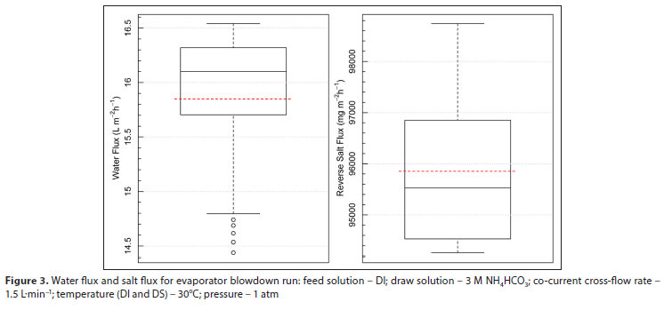
The distribution of each variable is visually presented using standard box and whisker plots (maximum and minimum values, 25th percentile (bottom of the box), median (middle line in the box), average (red dotted line in the box), and 75lh percentile (top of the box)).
Water flux and salt flux (pure water as feed]
Figure 3 shows the water fluxes and salt fluxes, respectively, when the FO-TFC membrane was tested with the active layer facing the deionized water (AS-DI) using 3 M ammonium bicarbonate as a draw solution.
The average water and salt fluxes obtained for the membrane characterisation run were 15.8 (SD = 0.6) L-m-2h-1 and 95 852 (SD = 1 494) mg-m-2h-1, respectively. The standard deviation shows that there was minimal variation in the water flux throughout the experiment, and this was to be expected as the run was conducted at a constant draw solution concentration. The osmotic pressure exerted by the feed water is negligible to alter the osmotic driving force significantly. On average, the conductivity in the feedtank was 0.42 mS-cm-1 with a maximum of 0.63 mS-cm-1. These conductivities are very low compared to that observed for the draw solution (mean = 141.8, SD = 0.5 mS-cm-1). It is evident from the reverse salt flux plot that there was a significant amount of draw solution that diffused back to the feed water tank (DI). This was also confirmed by the continuous increase in feed water conductivity as the run progressed. The specific reverse salt flux (SRSF) for this membrane using the average water flux and reverse salt flux was 6.1 g of ammonium bicarbonate per litre of product water. The SRSF is, however, high and its impact when interacting with the synthetic evaporator blowdown feed solution could be significant. Reverse salt diffusion is an essential parameter to the FO process because it brings complexity to the feed water concentrate management and could potentially contribute to decreasing the net osmotic potential or driving force leading to reduced water fluxes. Furthermore, reverse salt diffusion could also increase the fouling potential of the feed solution due to the formation of scaling compounds with the feed constituents. Reverse salt diffusion also results in draw solution loss which could require replenishment and add to the operating costs.
Baseline and synthetic runs
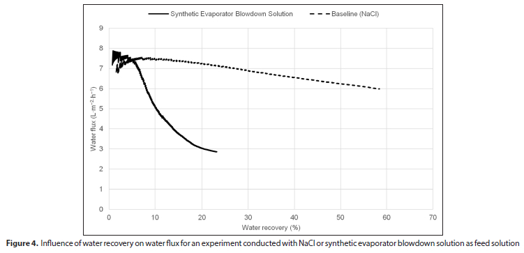
To investigate the impact of decreasing the osmotic driving force on the water recovery and flux, sodium chloride solution (osmotic pressure the same as the synthetic evaporator blowdown solution to be used) was used as a baseline. After this, the simulated synthetic evaporator blowdown solution was tested to evaluate the feasibility of using FO technology to treat this stream. Figure 4 shows the influence of water recovery on water flux during the baseline and synthetic run.
The initial water flux during the baseline experiment with NaCl as a feed solution (bench-scale unit was operated until a 58% water recovery) was around 7.5 L m-2 h-1, and it decreased to a final water flux of roughly 6 L-m2-h -l as the feed solution concentration or osmotic pressure increases. The conductivity of the feed solution increased from 56 mS-cm-1 to about 110 mS-cm-1, indicating that the feed solution was concentrated. The increase in feed solution concentration resulted in a decrease in osmotic driving force even though the DS concentration was kept constant, which resulted in a decline in water flux, as discussed in the above paragraph. The run was stopped at 58% feed volume recovery as the permeation rate had become very low due to the decreasing osmotic driving force. For the synthetic solution, the initial flux (after the steady state was established) was around 7.8 L-m-2 h-1, and the flux decreased to a final water flux of ~2.9 L-m-2 h-1 (operated until approximately 22% feed volume recovery). As indicated in Fig. 4 above, the water flux trend is very different from that of the baseline run, and this was a clear indication of potential premature membrane fouling. The inspection of the membrane coupon after the experiment showed that the membrane was also severely fouled with a white precipitate.
FO membrane morphology
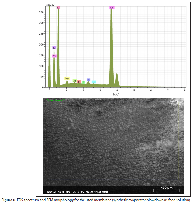
The morphology of virgin and used membranes was studied to evaluate the effect of synthetic evaporator blowdown feed solution on the membrane performance. It has been extensively reported in the literature that in the case of feed and draw solutions containing scale-forming ions (e.g., Sr2+, Ba2+, Ca2+, Mg2+, S042-, F1- and CO,2-), scaling due to minerals generally occurs on the membrane surface (active layer side of the membrane) when the feed solution components are concentrated above the solubility limits of various water-soluble minerals such as CaCO3, SrSO4, CaF, BaSO4, CaSO4 (Achilli et al, 2010). The feed and draw solution for this particular experiment contained scale precursors such as Ca2+, Mg2+, SO42 , SiO2, and CO32 . Figures 5 and 6 shows the EDS spectrum and SEM images for the blank and used membrane, respectively.
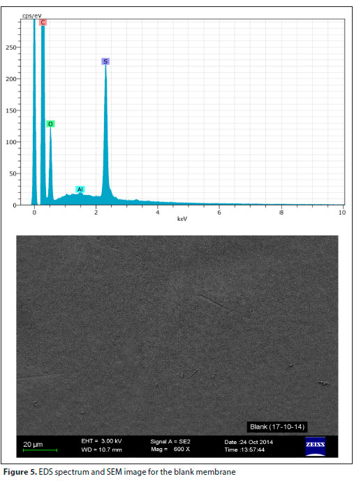
The EDS spectrum shows that C, O, and Ca are major elements on the used membrane coupon with the minor elements being Na, Si, P, Al, and CI. SEM morphology showed that the membrane coupon was severely fouled. Raman spectroscopy was used to determine the type of minerals responsible for the fouling observed. Raman spectra obtained on the white particulates of the fouled membrane coupon identified CaCO, to be present on the membrane sample but in different polymorphic forms. Both polymorphs had bands at 154 and 1 085 cm 1 with the latter being the vs (CO3-2) band. Aragonite has unique bands at -205 and 704 cm-1 and calcite at ~ 279 and 709 cm-1.
From the FO membrane morphology results, it can be deduced that the steep flux decline observed in Fig. 4 is associated with the precipitation of calcium carbonate onto the membrane surface due to the interaction of scaling precursors in the feed solution (Ca2+) and draw solution (CO,). The draw solution-induced calcium carbonate scaling was also observed by Li et al, (2015) when evaluating the feasibility of using the FO process to desalinate seawater using ammonium bicarbonate as a draw solution. The SRSF observed in the Li et al. (2015) study was 12 g-L 1 (even higher than what was observed during this study). Li et al. (2015) showed that the scaling occurs early in the process, as observed during this study. The EDS spectrum of the membrane showed that the membrane sample contained calcium as a major element (similar to what was observed with the synthetic evaporator blowdown stream). Scaling observed in the Li et al. study showed a typical aragonite cluster (similar to what was observed in this study). Li et al. (2015), however, indicated that the membrane permeability lost due to the experienced scaling could be recovered (albeit not 100%) using hydraulic cleaning (increased cross-flow velocity), Al-Furaiji (2009) investigated the treatment of hypersaline produced water using the FO process. Severe scaling effects were observed when using NH,-C02 draw solution, which resulted in a reduction in the forward osmosis water flux and recoveries. Calcium carbonate was found to be the main component that caused the observed scaling. Formation of the calcium carbonate was found to be due to the interaction between the calcium ions that exist in the feed solution with carbonate ions from the draw solution. Furthermore, the transport of the draw solution to the feed side of the membrane causes a pH increase at the feed side which subsequently promotes favourable conditions for calcium carbonate precipitation.
The implication is that for high-hardness brine streams a hardness removal step (complete or partial hardness removal), in particular for calcium hardness, may be required to make the ΓΟ process viable.
Evaluation of the impact of hardness removal on the FO process using synthetic evaporator blowdown as feed solution
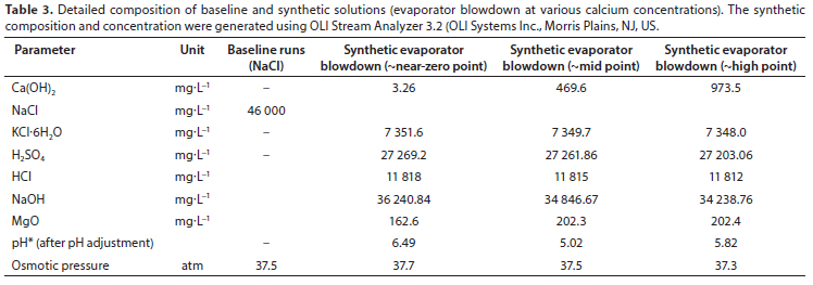
A follow-up study was conducted to understand the impact of calcium concentration on FO membrane fouling. Three scenarios were evaluated (i.e., complete removal of hardness (near-zero calcium concentration scenario), partial removal of hardness (50% calcium concentration), and 100% calcium concentration scenario).
Table 3 summarises the feed composition of baseline and synthetic evaporator blowdown solutions used for follow-up experiments.
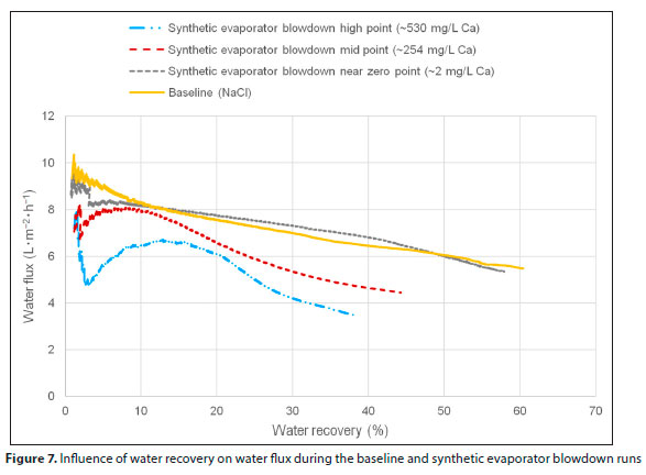
Figure 7 shows the influence of water recovery on water flux during the baseline and synthetic evaporator blowdown runs.
As indicated in Fig. 7, the water flux trend for the synthetic evaporator blowdown feed solution at almost-zero calcium concentration (~2 mg-L-1) is very similar to that of the baseline run (NaCl), and this is a clear indication that there was no change in FO membrane performance or FO membrane fouling induced by softened synthetic evaporator blowdown feed solution. 'Ihe SEM-EDX spectra and visual inspection of the used membrane coupon showed that the membrane coupon had no noticeable fouling on the surface.
It is also evident from flux vs. water recovery trends in Fig. 7 that, for feed solutions containing calcium concentration at -254 mg L-1 and -530 mg L-1, fouling of the membrane was observed. The synthetic evaporator blowdown feed solution containing -250 mg-L-1 calcium concentration, however, showed less fouling when compared to the feed solution containing -530 mg-L 1 (comparing water flux decline and water recovery achieved).
This result indicates that complete softening of the evaporator blowdown feed solution might not be required as the performance of the FO process could potentially be sustained by removing just enough calcium from the feed solution. Although the EDS and infrared spectra confirmed calcium carbonate precipitation for both cases (i.e., middle and high calcium concentration), SEM morphology and visual observation showed that the high-calcium-concentration membrane coupon was heavily fouled when compared to the medium-calcium-concentration membrane coupon (Sitabule, 2021).
Figure 7 also shows that the water flux initially decreased, which was followed by an increase, and it was hypothesized that this was due to the initial 'non-permanent' fouling that occurs (removable by cross-flow). Once this fouling was removed, it was hypothesized that the water flux would increase and then decrease as water recovery was increased. This hypothesis was recommended for further investigation.
CONCLUSIONS
FO was evaluated for the concentration of synthetic evaporator blowdown stream using ammonium bicarbonate as a draw
solution. The evaporator blowdown stream is characterized by high TDS, which makes it challenging for conventional desalination technologies such as reverse osmosis. Furthermore, this stream has scaling pre-cursor components (Ca+2, Ba+2, Sr+2, SO4-2, CO3-2) which could result in the precipitation of sparingly soluble compounds such as calcium carbonate, barium sulphate, strontium sulphate, and calcium sulphate. The batch studies conducted using deionized water as feed (membrane characterization in terms of flux and reverse salt flux) have shown that specific reverse salt flux for the TFC membrane coupons used ranged from 6 to 7.4 g-L-1 of ammonium bicarbonate. This specific reverse salt flux is high and has the potential to impact the feed water chemistry and subsequently result in draw solution-induced membrane fouling due to the interaction of scaling precursors in the feed (Ca2+, Mg2+, S042-) with the scale precursors (CO,2) in the draw solution. The results from the batch studies conducted using synthetic evaporator blowdown (thermal evaporator blowdown: ~60 000 mg-L 1 TDS) solutions showed that the evaporator blowdown stream has a high fouling propensity. This observation was based on both the hydraulic performance (water flux and water recovery) as well as membrane morphology studies conducted on the used membrane coupons.
Membrane surface characterization conducted on the used TFC membrane coupons showed that the membrane surface was fouled with aragonite and calcite. Formation of the aragonite and calcium carbonate was found to be due to the interaction between the calcium ions that exist in the feed solution with carbonate ions from the draw solution, as observed by other authors. Furthermore, the experiments conductedto evaluate the impact of hardness removal (calcium hardness) on FO process performance using synthetic evaporator blowdown as feed solution showed that, in the absence of some hardness (complete or partial removal of calcium and magnesium), water fluxes and water recoveries of 4-6 L-m-2-h-1 and 45-60%, respectively, could be achieved. It was concluded in this study that the concentration of the calcium ions in the feed does have an impact on the formation of the calcium carbonate scale, implying that some hardness can be tolerated in the feed to the forward osmosis process.
The study provided a valuable fundamental understanding of the application of FO technology for treating high- salinity brines from the petrochemical and power generation industry. FO technology using ammonium bicarbonate as a draw solution can be considered as an alternative technology to treat concentrated brine streams from inland industries, provided some pre-treatment to remove scaling precursors such as calcium is incorporated in the flow scheme. These results could lead to a further reduction in the capital cost for the technology as only partial softening of the feed water could be required. Furthermore, there could be a reduction in operational costs associated with softening chemicals. The mechanism of fouling was also demonstrated in this study, which confirms that the high specific reverse salt flux was responsible for the scale formation which contributed to the water flux decline observed. The high specific reverse salt flux observed reinforced the need for more research on the draw solution and FO membrane.
ACKNOWLEDGMENTS
• Sasol Research & Technology management for supporting the development of forward osmosis (FO) technology
• WRC for supporting the development of FO technology
AUTHOR CONTRIBUTIONS
EN Sitabule: Conceptualization and methodology of the study, data collection and fieldwork, sample/data analysis, interpretation of results, writing of the initial draft, and revision after review. C Buckley: supervisor, reviewing the manuscript.
CONFLICT OF INTEREST
The authors declare no conflict of interest.
REFERENCES
AL-FURAIJI M (2016) Hyper-saline produced water treatment for beneficial use. PhD thesis, The University of Twente. [ Links ]
BACKER SN, BOUAZIZ I, KALLAYI N, THOMAS RT. PREETHIKUMAR G, TAKRIFF MS, LAOUI T and ATIEH MA (2022) Review: Brine solution: current status, future management and technology development. Sustaínabílíty 14 6752. https://doi.org/10.3390/sul4116752 [ Links ]
CATH T, ELIMELECH M, MCCUTCHEON J, MCGINNIS R, ACHILLI A, ANASTASIO D, BRADY A, CHILDRESS A, FARR I, HANCOCK N, LAMPI J, NGHIEM L, XIE M and YIP N (2013) Standard methodology for evaluating membrane performance in osmotically driven membrane processes. Desalination 312 31-38. https://doi.org/10.1016/j.desal.2012.07.005 [ Links ]
GOH P, MATSUURA T, ISMAIL A and NG B (2017) The water-energy nexus: solutions towards energy-efficient desalination. Energ. Technol. 5 (8) 1136-1155. https://doi.org/10.1002/ente.201600703 [ Links ]
GOKEL G and DEAN J (2004) Dean s Handbook Of Organic Chemistry. McGraw-Hill, New York. [ Links ]
HANCOCK N and CATH T (2009) Solute coupled diffusion in osmotically driven membrane processes. Environ. Sci. Technol. 43 (17) 6769-6775. https://doi.org/10.1021/es901132x [ Links ]
LI Z, VALLADARES LINARES R, BUCS S, AUBRY C, GHAFFOUR N, VROUWENVELDER J and AMY G (2015) Calcium carbonate scaling in seawater desalination by ammonia-carbon dioxide forward osmosis: Mechanism and implications, J. Membr. Sci. 481 36-43. https://doi.org/10.1016/j.memsci.2014.12.055 [ Links ]
MCGINNIS R, HANCOCK N, NOWOSIELSKI-SLEPOWRON M and MCGURGAN G (2013) Pilot demonstration of the NH3/C02 forward osmosis desalination process on high salinity brines. Desalination 312 67-74. https://doi.org/10.1016/j.desal.2012.11.032 [ Links ]
MORILLO J, USERO J, ROSADO D, EL BAKOURI H, RIAZA A and BERNAOLA F (2014) Comparative study of brine management technologies for desalination plants. Desalination 336 32-49. https://doi.org/10.1016/j.desal.2013.12.038 [ Links ]
NATHOO J, JIVANJI R and LEWIS A (2009) Freezing your brines off: eutectic freeze crystallization for brine treatment. Presented at: International Mine Water Conference, 19-23 October 2009, Pretoria. [ Links ]
OASYS (2014) Oasys Water - case studies. URL: http://oasyswater.com/solutions/case-studies-2/ (Accessed 26 June 2014). [ Links ]
OLISYSTEMS.COM (2011) A guide to using OLI Analyzer Studio Version 3.2 URL: www.olisystems.com/oli-studio-stream-analyzer (Accessed 7 July 2011). [ Links ]
PENDERGAST M, NOWOSIELSKI-SLEPOWRON M and TRACY J (2016) Going big with forward osmosis. Desalin. Water Treat. 57(55) 26529-26538. https://doi.org/10.1080/19443994.2016.1168581 [ Links ]
RSA (Republic of South Africa) (1998) National Water Act (Act 36 of 1998), section 56 (1). Government Gazette 19182. Government Printer, Cape Town. [ Links ]
SEMIAT R (2008) Energy issues in desalination processes. Environ. Sci. Technol. 42 (22) 8193-8201. https://doi.org/10.1021/es801330u [ Links ]
SHE Q, WANG R, FANE A and TANG C (2016) Membrane fouling in osmotically driven membrane processes: A review, J. Membr. Sci. 499 201-233. https://doi.org/10.1016/j.memsci.2015.10.040 [ Links ]
SITABULE NE (2021) Evaluation of forward osmosis technology for the treatment of selected concentrated brines. PhD thesis, University of KwaZulu-Natal. [ Links ]
LANG W and NG H (2008) Concentration of brine by forward osmosis: Performance and influence of membrane structure. Desalination 224 (1-3) 143-153. https://doi.org/10.1016/j.desal.2007.04.085 [ Links ]
LSAI J-H, MACEDONIO F, DRIOLI E, GIORNO L CHOU C-Y, HU F-C, LI CL, CHUANG CJ and TUNG K-L (2017) Membrane-based zero liquid discharge: Myth or reality?, J. Taiwan Inst. Chem. Eng. 80 192-202. https://doi.org/10.1016/j.jtice.2017.06.050 [ Links ]
WANLING T (2009) Forward (direct) osmosis: a prospective membrane process. PhD thesis, National University of Singapore. [ Links ]
WATSON I, MORIN O and HENTHORNE L (2003) Desalting Handbook For Planners (3rd edn). Bureau of Reclamation, Denver Federal Center, Denver, Colo. 316 pp. [ Links ]
XIE M, NGHIEM L, PRICE W and ELIMELECH M (2012) Comparison of the removal of hydrophobic trace organic contaminants by forward osmosis and reverse osmosis. Water Res. 46 (8) 2683-2692. https://doi.org/10.1016/j.watres.2012.02.023 [ Links ]
ZHAO S, ZOU L, TANG C and MULCAHY D (2012) Recent developments in forward osmosis: Opportunities and challenges. J. Membr. Sci. 3961-21. https://doi.org/10.1016/j.memsci.2011.12.023 [ Links ]
 Correspondence:
EN Sitabule
Email: enos.sitabule@sasol.com
Received: 1 March 2022
Accepted: 21 November 2022

