


Services on Demand
Article
 English (pdf)
 Article in xml format
 Article references
Indicators

Related links
-
 Cited by Google
 -
 Similars in Google
Share

 Permalink
Water SA
On-line version ISSN 1816-7950
Print version ISSN 0378-4738
Water SA vol.48 n.1 Pretoria Jan. 2022
http://dx.doi.org/10.17159/wsa/2022.v48.i1.3910
RESEARCH PAPER
Predicting the head leakage behaviour of cracks in pipe elbows
Moustafa S Darweesh
Civil Engineering Department, Assiut University, Assiut, Egypt
ABSTRACT
In this study, finite element analysis (SAP2000 program) was used to investigate the relationship between the pressure and leakage area in 90° pipe elbows with longitudinal, spiral, and circumferential cracks. The results show that leakage areas expand linearly as the internal pressure increases and its inclination is called the pressure-area slope (m). A sensitivity study was conducted to recognize the influence of different parameters (inside diameter, wall thickness, modulus of elasticity, longitudinal stress, Poisson's ratio, and finally crack orientation) on both m and leakage exponent (N). The results reveal that the elasticity modulus has the dominant impact on m, followed by elbow wall thickness, and then elbow inside-diameter. The Poisson's ratio and the longitudinal stress have an insignificant influence on m. Moreover, the slope m varies more in the longitudinal and spiral cracks than the circumferential cracks. The amount of leakage through the different cracks is a function of the internal pressure raised to an exponent ranging from 0.5 to 1.01. An attempt was made to find empirical equations to express the pressure-area slope as a function of elbow properties and crack orientation. The study's findings were checked against numerical and experimental results and good correlations were obtained.
Keywords: cracks, finite element model, leakage, pipe elbows, pressure
INTRODUCTION
Deterioration and aging of water pipelines and instruments have led to many problems, such as leakage, for municipalities, water utilities, and engineers. Leakage not only reduces utilities' revenue but also diminishes water quality and wastes energy (Giustolisi et al., 2008). According to Rogers (2014), water losses within some pressurized water networks due to leakage may exceed 50%. Leak quantity depends on the network operating pressure, the pipeline diameter, age and material, and the leak configuration (Lambert, 2002; Saghi and Aval, 2015). The amount of water loss via leaks can be described by the conventional orifice formula deduced from Bernoulli's equation:
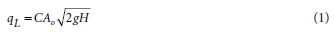
where qL is outflow rate of leakage, C is discharge coefficient, Ao is orifice area, g is the gravitational acceleration, and H is orifice pressure drop.
A laboratory study was conducted by Shao et al. (2019), who concluded that leakage or intrusion discharge through different orifice shapes does not undergo the classical orifice equation. Regardless of the hole geometry and size, its flow rate can be represented by the widespread expression (Greyvenstein and Van Zyl, 2007; Sadr-Al-Sadati and Jalili Ghazizadeh, 2019a) as follows:

where K is leakage coefficient and N is pressure (leakage) exponent.
Further investigation found that N varies widely from the typical value of 0.5 (De Marchis et al., 2016). The leakage exponent can range from 0.47 to 2.5 and depends on the characteristics of the pipeline and soil, and crack attributes (Walski et al., 2009). Darweesh and Hussien (2020) studied the numerical relationship between leakage and water pressure for circular holes in water pipe bends. They found that the exponent N ranges from 0.495 to 0.592.
Several studies have shown that the leakage area does not remain constant, as stated in Eq. 1, but varies as the pressure in the pipeline changes (De Marchis and Milici, 2019; Sadr-Al-Sadati and Jalili Ghazizadeh, 2019b; Kabaasha et al., 2020). The deformed area, after exerting the pressure, can be expressed as:

where Ao is the primary crack area and AA is the change in crack area. For the elastic deformation phase, irrespective of crack orientation, the relationship between fluid pressure and leak area can be given (Cassa et al., 2010; Van Zyl et al., 2017; Kabaasha et al., 2018) by:

where m is the pressure-area slope. By combining Eq. 4 and Eq. 1, one can have the fixed and variable area discharges (FAVAD) concept (May, 1994):

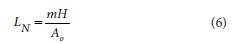
It is notable from Eq. 5 that the leakage outflow is related to a pressure exponent ranging from 0.5 to 1.5. By dividing the first and second terms of Eq. 5, Cassa and Van Zyl (2011) get a new term named leakage number (LN):
Van Zyl and Cassa (2014) and Van Zyl et al. (2017) developed a relationship that links leakage exponent and leakage number:

Mazumder (2012) and Muftah (2014) used the computational fluid dynamics (CFD) technique to predict pressure distribution in elbow ducts with different fluid types. In our study, the impact of pressure on leakage area in long radius elbows with spiral, circumferential, and longitudinal cracks (SC, CC, and LC, respectively) was systematically investigated. The effects of elbow properties, including Poisson's ratio, elasticity modulus, longitudinal stress, wall thickness, and inside diameter, on the pressure area slope m and leakage exponent, were examined. Finite element models were created in SAP2000 (2012) v15.2.0 software. This research supposed that the pipeline elbow was filled with fluid, the cracks were modelled at the central outer side of elbows, the fluid was discharged into the atmosphere, and the surrounding soil and plastic deformation were disregarded.
METHODOLOGY
Finite element model setup
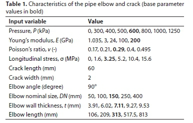
Finite element analysis (FEA) is a numerical method that describes an item, e.g., pipe or elbow, as a group of nodes and elements. An elbow model contains a mix of solid elements; each element was solved alone, and then from the continuity equation all elements were reunited to get a final solution. This paper assigns finite elements to study the manner of rectangular slits (cracks) in pressurized water elbows by a 3D model, as presented in Fig. 1a; a cross-section of the model is shown in Fig. 1b. In addition to the SAP finite element model, a program designed by the author to calculate the deformed crack's area was used in this study. The characteristics and dimensions of the tested elbow are shown in Table 1. Eight-node solid elements, as shown in Fig. 2, were used within the elbows. To ensure a reasonable accuracy, the element sizes differ and become smaller around the crack. The mesh elements vary in size from 2 mm in the region around the cracks to 5 mm for the rest of the elbow model. Hinge supports were applied to model the elbow pipe boundary conditions (Fig. 1a).


The water pressure can be considered as a uniform load that acts outward from the elbow, and the longitudinal elbow stresses can be simulated as external stresses at the elbow ends. The elbows were presented at a horizontal level. In the biaxial load case, the longitudinal stresses were determined as follows (Hibbeler, 2010):
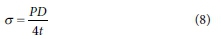
where P is the water pressure, D is the elbow inside-diameter, t is the elbow wall thickness, and o is the longitudinal stress.
Leakage modelling
This research was achieved on a base model (bold values in Table 1) of a 90° elbow of steel with 154.05 mm internal diameter, 7.11 mm wall thickness, and 313 mm length (ASME, 2012). Generally, the curvature length is equal to 1.5 times the elbow inside-diameter. A sensitivity analysis was carried out by changing a single variable per time, whereas the other variables were kept the same. This procedure was done for every parameter to understand its influence on the pressure-area slope of the elbow. The chosen values correspond to the common ranges considered in the field of water distribution systems (WDSs).
RESULTS AND DISCUSSION
Influence of various parameters on pressure-area slope (m)
The system pressure was plotted versus leak area for various crack shapes within a 90° long radius elbow, as shown in Fig. 3. It is clear from the figure that the crack area is directly proportional to the pressure. These findings agree with the analytical outcomes of Schwaller and Van Zyl (2015), and the experimental results of Ferrante (2012). Also, the leakage area expands by a higher rate, i.e., has a larger gradient for spiral cracks than the other crack types (longitudinal and circumferential).

A sensitivity study was performed to examine the effect of every parameter on the pressure-area gradient m. This was achieved by fixing all the specified variables, except an individual variable that was permitted to change based on Table 1. Figure 4 manifests the pressure-area slope versus every one of the examined parameters. In Fig. 4a, for all crack shapes, elasticity modulus E is inversely proportional to the slope m. Figure 4b shows that the slope m is directly proportional to the elbow inside-diameter raised to powers of 2.08, 0.79, and only 0.26, for CC, SC, and LC, respectively. It is also noticed that for small elbow diameters (< 250 mm), m varies more in the longitudinal cracks than the circumferential cracks. On the contrary, for larger diameters (> 250 mm), m varies more in the circumferential cracks than the longitudinal cracks. The spiral cracks, for all elbow diameters, have a medium influence between LC and CC. According to Figs 4c and 4d, the longitudinal stress (a) and the Poisson's ratio (v) have a trivial influence concerning the pressure-area slope for all crack shapes. In Fig. 4e, the slope m, for all crack directions, is inversely proportional to the elbow wall thickness raised to exponents of 1.63, 1.76, and 0.96 for SC, LC, and SC, respectively.

To specify which of the studied parameters has the dominant influence on the pressure-area gradient, finite element outcomes for the slope m were drawn vs all variables, as shown in the bar graph (Fig. 4f). It can be inferred from the figure that the modulus of elasticity E, for all cracks, has the most significant impact on the pressure-area slope, followed by the elbow wall thickness, and the elbow inside-diameter. The longitudinal stress and the Poisson's ratio have a negligible impact on m.
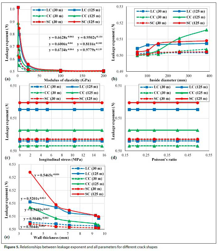
Relationship between leakage exponent (N) and different parameters
Leakage exponent N is commonly applied in the field of water supply systems. LNwas first determined from Eq. 6, and then N was calculated from Eq. 7. Two pressure values were considered: 30 and 125 m H2O. Leakage exponents were plotted versus the different parameters for various crack types, as depicted in Fig. 5. It is quite clear that the leakage exponent is inversely proportional to Young's modulus and elbow thickness, whereas it is directly proportional to the inside-diameter. Again, the longitudinal stress and Poisson's ratio have insignificant effects regarding N. Furthermore, the graphs yielded a leakage exponent of 1.01 for spiral and longitudinal cracks, while this reaches 0.89 for circumferential cracks. These values vary greatly from what the orifice's equation suggests (0.5), which means that leak outflow is more sensitive to the system pressure than the orifice equation indicates.
Developing equations for pressure-area slope (m)
Regression analysis is a data processing approach used to develop an expression that links parameters. An exponential regression model (Carlberg, 2016) was applied to derive a formula that relates the pressure-area slope in terms of the elbow properties and the crack dimensions. Empirical equations (SI units) were proposed for circumferential, spiral, and longitudinal cracks, respectively, through a 90° long radius elbow as follows:

With the aid of these equations, the change in crack area can be calculated for different elbow diameters, materials, crack orientations, and pressure values, instead of neglecting its value.
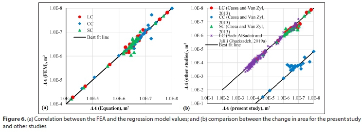
The predicted values of AA by Eqs. 9-11 were compared to the FEA data in Fig. 6a for all crack shapes. In addition, the results of current study were verified with other published works, for instance, numerical results of Cassa and Van Zyl (2013), for the different crack types, and experimental data of Sadr-Al-Sadati and Jalili Ghazizadeh (2019a) for longitudinal slits in straight polyethylene pipelines (Fig. 6b). Note that logarithmic scales were used on both axes. It is seen from Fig. 6a that the leakage area calculated by the regression analysis model matches the FEA data well and the correlation coefficient (R2) is equal to 94, 94, and 98% for circumferential, spiral, and longitudinal cracks, respectively. Good agreements were found with Cassa and Van Zyl (2013), with R2ranging from 96% for longitudinal and spiral cracks to 83% for circumferential cracks, as well as with the experimental study (R2 = 92%). The numerical results of CC do not agree well with those of Cassa and Van Zyl (2013), and this may be due to the fact that the current study neglected longitudinal stresses, unlike Cassa and Van Zyl's (2013) study.
After verification of the obtained FEM data, the pressure-area slopes for circumferential, spiral, and longitudinal cracks were calculated using the following equations:
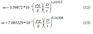

As mentioned previously, the longitudinal stress and the Poisson's ratio have very little impact concerning the pressure-area slope and subsequently were omitted from the equations. By combining Eq. 5 and Eqs 12-14, the leak outflow within a crack can be represented as:
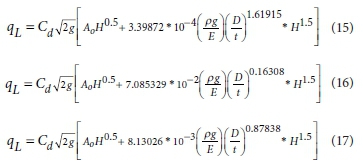
From the derived equations, the pressure-area slope for different crack orientations within a 90° long radius elbow can be predicted using its characteristics and the crack orientation.
Further investigations are required to study the effect of both crack length, width, and position along the elbow on the pressure-area slope through different angled elbows that undergo elastic and plastic deformations. Also, laboratory tests and/or field measurements are recommended to validate the obtained results.
CONCLUSIONS
This paper investigates the behaviour of longitudinal, spiral, and circumferential cracks in 90° pipe elbows under pressure. Finite element analysis (SAP2000 software) was applied to analyse the relationship between the pressure and the crack area. The results point out that the leak area grows linearly with pressure. A parametric study was conducted to show the effect of various parameters (internal diameter, thickness, material, longitudinal stress, Poisson's ratio, and crack direction) on both pressure-area slope (m) and leakage exponent (N). The results demonstrate that Young's modulus has the most significant influence on the slope m, followed by elbow wall thickness and elbow inside-diameter. The Poisson's ratio and the longitudinal stress have negligible effects on m, for all crack types. Furthermore, longitudinal and spiral cracks have a greater effect on the slope m than the circumferential cracks. The leakage flow rate through the different cracks is a function of the internal pressure, with an exponent ranging from 0.5 to 1.01. Reasonable equations were developed to predict the pressure-area slope in terms of crack orientation and elbow properties. Good agreements were observed between the current results and those of experimental and numerical studies.
ACKNOWLEDGMENTS
The author would like to express his deepest gratitude to Dr Osama S Hussien, Associated Professor in Civil Engineering Department, Al-Azhar University, Cairo, Egypt, for his valuable assistance in modelling the pipe elbows in SAP2000 program.
REFERENCES
ASME (American Society of Mechanical Engineers) Standard: ASME B16.9-2012 (2012) Factory-made wrought buttwelding fittings. ASME, New York. 52 pp. [ Links ]
CARLBERG C (2016) Regression Analysis Microsoft Excel. Que Publishing, Indianapolis. 364 pp. [ Links ]
CASSA AM and VAN ZYL JE (2011) Linking the power FAVAD equations for modelling the effect of pressure on leakage. Proc. 11th International Conference on Computing and Control for the Water Industry (CCWI2011), 5-7 September 2011, Exeter. 551-556. [ Links ]
CASSA AM and VAN ZYL JE (2013) Predicting the head-leakage slope of cracks in pipes subject to elastic deformations. J. Water Supply Res. Technol. AQUA. 62 (4) 214-223. https://doi.org/10.2166/aqua.2013.094 [ Links ]
CASSA AM, VAN ZYL JE and LAUBSCHER RF (2010) A numerical investigation into the effect of pressure on holes and cracks in water supply pipes. Urban Water J. 7 (2) 109-120. https://doi.org/10.1080/15730620903447613 [ Links ]
DARWEESH MS and HUSSIEN OS (2020) Numerical investigation of leakage behaviour in long radius elbows. Water SA. 46 (1) 38-43. https://doi.org/10.17159/wsa/2020.v46.i1.7885 [ Links ]
DE MARCHIS M and MILICI B (2019) Leakage estimation in water distribution network: effect of the shape and size cracks. Water Reesour. Manage. 33 (3) 1167-1183. https://doi.org/10.1007/s11269-018-2173-4 [ Links ]
DE MARCHIS M, FONTANAZZA CM, FRENI1 G, NOTARO V and PULEO V (2016) Experimental evidence of leaks in elastic pipes. Water Resour. Manage. 30 (6) 2005-2019. https://doi.org/10.1007/s11269-016-1265-2 [ Links ]
FERRANTE M (2012) Experimental investigation of the effects of pipe material on the leak head-discharge relationship. J. Hydraul. Eng. 138 (8) 736-743. https://doi.org/10.1061/(ASCE)HY.1943-7900.0000578 [ Links ]
GREYVENSTEIN B and VAN ZYL JE (2007) An experimental investigation into the pressure-leakage relationship of some failed water pipes. J. Water Supply Res. Technol. AQUA. 56 (2) 117-124. https://doi.org/10.2166/aqua.2007.065 [ Links ]
GIUSTOLISI O, SAVIC D and KAPELAN Z (2008) Pressure-driven demand and leakage simulation for water distribution networks. J. Hydraul. Eng. 134 (5) 626-635. https://doi.org/10.1061/(ASCE)0733-9429(2008)134:5(626) [ Links ]
HIBBELER RC (2010) Mechanics of Materials (8th edn). Prentice Hall, Boston. 883 pp. [ Links ]
KABAASHA AM, PILLE O and VAN Zyl JE (2018) Incorporating the modified orifice equation into pipe network solvers for more realistic leakage modeling. J. Hydraul. Eng. 144 (2) 04017064-1-04017064-8. https://doi.org/10.1061/(ASCE)HY.1943-7900.0001410 [ Links ]
KABAASHA AM, VAN ZYL JE and MAHINTHAKUMAR G (2020) Correcting power leakage equation for improved leakage modeling and detection. J. Water Resour. Plann. Manage. 146 (3) 06020001-106020001-7. https://doi.org/10.1061/(ASCE)WR.1943-5452.0001172 [ Links ]
LAMBERT AO (2002) International report: Water losses management and techniques. Water Supply. 2 (4) 1-20. https://doi.org/10.2166/ws.2002.0115 [ Links ]
MAY JH (1994) Pressure dependent leakage. World Water Environ. Eng. 17 (8) 10. [ Links ]
MAZUMDER QH (2012) CFD analysis of the effect of elbow radius on pressure drop in multiphase flow. Modell. Simul. Eng. 112 (37) 1-8. https://doi.org/10.1155/2012/125405 [ Links ]
MUFTAH AM (2014) 3D fluid flow in an elbow meter-CFD model. Sirte Univ. Sci. J. 4 (1) 35-42. [ Links ]
ROGERS D (2014) Leaking water networks: an economic and environmental disaster. Procedia Eng. 70 1421-1429. https://doi.org/10.1016/j.proeng.2014.02.157 [ Links ]
SADR-AL-SADATI SA and JALILI GHAZIZADEH M (2019a) Experimental investigation on pressure-leakage relation for high-density polyethylene pipe. Urban Water J. 16 (4) 289-298. https://doi.org/10.1080/1573062X.2019.1669192 [ Links ]
SADR-AL-SADATI SA and JALILI GHAZIZADEH M (2019b) The experimental and numerical study of water leakage from high-density polyethylene pipes at elevated temperatures. Polym. Test. 74 274-280. https://doi.org/10.1016/j.polymertesting.2019.01.014 [ Links ]
SAGHI H and AVAL AA (2015) Effective factors in causing leakage in water supply systems and urban water distribution networks. Am. J. Civ. Eng. 3 (2-2) 60-63. https://doi.org/10.11648/j.ajce.s.2015030202.22 [ Links ]
SAP2000 (2012) Integrated Finite Element Analysis and Design of Structures. Version 15.2.0. Computers and Structures Inc., Berkeley. [ Links ]
SCHWALLER J, VAN ZYL JE and KABAASHA AM (2015) Characterising the pressure-leakage response of pipe networks using the FAVAD equation. Water Supply. 15 (6) 1373-1382. https://doi.org/10.2166/ws.2015.101 [ Links ]
SHAO Y, YAO T, GONG J, LIU J, ZHANG T and YU T (2019) Impact of main pipe flow velocity on leakage and intrusion flow: an experimental study. Water. 11 (1) 118-129. https://doi.org/10.3390/w11010118 [ Links ]
VAN ZYL JE and CASSA AM (2014) Modeling elastically deforming leaks in water distribution pipes. J. Hydraul. Eng. 140 (2) 182-189. https://doi.org/10.1061/(ASCE)HY.1943-7900.0000813 [ Links ]
VAN ZYL JE, LAMBERT AO and COLLINS R (2017) Realistic modeling of leakage and intrusion flows through leak openings in pipes. J. Hydraul. Eng. 143 (9) 04017030-1-04017030-7. https://doi.org/10.1061/(ASCE)HY.1943-7900.0001346 [ Links ]
WALSKI T, WHITMAN B, BARON M and GERLOFF F (2009) Pressure vs. flow relationship for pipe leaks. Proc. World Environmental and Water Resources Congress, ASCE, 17-21 May 2009, Kansas City. 93102. https://doi.org/10.1061/41036(342)10 [ Links ]
 Correspondence:
Moustafa S Darweesh
Email: eng_taftaf82@yahoo.com
Received: 7 June 2021
Accepted: 12 January 2022

