


Servicios Personalizados
Articulo
 Inglés (pdf)
 Articulo en XML
 Referencias del artículo
Indicadores

Links relacionados
-
 Citado por Google
 -
 Similares en Google
Compartir

 Permalink
Water SA
versión On-line ISSN 1816-7950
versión impresa ISSN 0378-4738
Water SA vol.45 no.1 Pretoria ene. 2019
http://dx.doi.org/10.4314/wsa.v45i1.16
ORIGINAL ARTICLES
Model test and numerical investigation of the effect of the impervious layer's slope on seepage characteristics under hydraulic structures
Rasool GhobadianI, *; Hamed ShekariI; Parisa KoochakII
IDepartment of Water Engineering, PO Box 1158, Razi University, Kermanshah, Iran
IIShahid Chamran University, Ahvaz, Iran
ABSTRACT
Although the impervious layer under a hydraulic structure is rarely flat, the effect of the impervious layer's slope, under the hydraulic structure, on seepage characteristics has not been studied to date. Therefore, this study investigated the effect of the downhill and uphill impervious layer's slope (downhill/uphill foundation slopes) on the uplift pressure, seepage discharge and exit gradient under hydraulic structures. In order to reach this goal, a numerical model has been developed in which the general equation of fluid flow in non-uniform; anisotropic soil is solved by the finite volume method on a structured grid. The model validation was performed using the measured data from experimental tests. The results of the model validation indicated that the model calculates the seepage discharge and uplift pressure with a maximum error of less than 3.79% and 3.25%, respectively. The results also indicated that by increasing the downhill foundation slope (DFS) the uplift force decreases, but the exit gradient and seepage discharge increase. Moreover, by increasing the uphill foundation slope (UFS), the uplift force increases but the exit gradient and seepage discharge decrease. In addition, the results demonstrate that by increasing the length of the cut-off wall the effect of the DFS on decreasing and UFS on increasing the uplift pressure force becomes more severe. However, the effect of the DFS on increasing the seepage discharge and UFS on decreasing the seepage discharge becomes milder as the length of the cut-off wall increases. By increasing the DFS, from zero to −15%, the exit gradient increases 19.75% and 14.4% for 1 m and 6 m cut-off lengths, respectively.
Keywords: hydraulic structures, foundation slope, cut-off length, uplift pressure, numerical simulation, seepage discharge, exit gradient
INTRODUCTION
One of the major issues that affects hydraulic structures is water seepage. The water stored on the upstream side of a concrete dam seeps through the dam foundation and tries to emerge on the downstream end, due to the difference between the upstream and downstream head. The seeping water creates a hydraulic gradient between the upstream and downstream side of the dam. This hydraulic gradient causes a vertical upward pressure that is known as uplift pressure. The uplift pressure reduces the effective weight of the structure, which leads to the reduction of the resistance force. Therefore, it is essential to identify the parameters which affect the seepage characteristics, such as seepage discharge, uplift pressure and exit gradient. These parameters have been the subject of many studies in the past.
Griffiths and Fenton (1997) combined the random field technique with the finite element method (FEM), in order to simulate 3D steady seepage within the soil body, in which the permeability was randomly distributed. Sedghi-Asl et al. (2005) studied the effects of the cut-off wall's location on reducing the seepage and flow velocity under hydraulic structures, by using the finite difference method (FDM). They found that the best position for the cut-off wall is at the upstream and downstream end. Zoorasna et al. (2008) studied the seepage through different cut-off wall connection systems of the Karkheh storage dam. According to their results, the cut-off wall's connection system is an important part that affects the flow in earth dams. They determined the most effective and suitable connection system, taking into consideration limits of construction. Fadel Alsenousi and Mohamed (2008) studied the effects of inclined cut-offs and soil foundation characteristics on the seepage beneath hydraulic structures. They developed a model to compute the piezometric head distribution for different flow conditions and soil characteristics. The results showed that changing the slope angle of the sheet pile and varying the soil and flow conditions effects the calculated exit gradient values, flow rates, and uplift pressure. Ghobadian and Khodaee (2009) investigated the effect of the cut-off wall and drainage on the uplift pressure force and exit gradient under the hydraulic structure, using the finite volume method (FVM). Their results indicated that the construction of a cut-off wall at each location reduces the value of the exit gradient. The highest amount of uplift pressure and the lowest value of hydraulic exit gradient are observed when the cut-off wall is located at the downstream end. Lashteh Neshaei et al. (2010) investigated the effect of various parameters, such as the length and position of cut-off walls, the position of the filter, the depth of the porous foundation and the type of soils, on uplift pressure and hydraulic gradient. Their results showed that the extra cut-off wall between the two lateral walls does not have a considerable effect on the uplift force or hydraulic gradient, while locating a proper filter in a suitable place can change the flow pattern and affect the design process. Baghalian and Nazari (2011) studied the prediction of uplift pressure under a diversion dam, using artificial neural network (ANN) and genetic algorithm (GA). Their test results were compared with actual data and other test results, which showed that the uplift pressure is predicted with good accuracy using this procedure. Zainal (2011) investigated the effect of the cut-off wall's angle on the seepage under the dam, using the SEEP/W computer program. The cut-off wall angle varied from 0° to 180°. According to their results, the best angles for minimizing the water flow, uplift pressure and exit gradient are about 60°, 120° to 135°, and 45° to 75°, respectively. Azizi et al. (2012) studied the effect of weep holes and the cut-off wall on the uplift pressure under the Yusufkand diversion dam in Mahabad, IRAN, using the Seep/w software. The results of this study indicated that the upstream cut-off wall with 8 m length decreases the uplift force about 63% and decreases the exit gradient 79% compared to the case without a cut-off wall. In addition, installing a weep hole in the downstream stilling basin decreases the uplift force 8% and decreases the exit gradient 74% compared to the case without a weep hole. Jelenkovi and Travaš (2013) developed a numerical model using the finite difference method to calculate the uplift pressure and velocity under a gravity dam. In this study, both numerical and experimental analysis of seepage were compared for a typical gravity dam. Mansuri and Salmasi (2013) studied the effectiveness of a horizontal drain and cut-off wall in reducing the seepage flow from an assumed zoned earth dam, using the Seep/w software. Their results showed that increasing the horizontal drain length increases the seepage rate and the hydraulic gradient. The results also indicated that the optimum location of the cut-off wall for reducing the seepage rate and piping is in the middle of the dam foundation. El Jumaily and Jaber Al-Bakry (2013) studied the effect of non-homogenous foundations on the uplift pressure and exit gradients and compared the results with homogenous foundations. They also studied the effect of the position of the cut-off wall on uplift pressure and exit gradient. Khan et al. (2013) developed a scaled model of the Golen Gol weir in Pakistan and analysed the seepage quantity, using the SEEP/W computer program. They considered different seepage control methods, such as: downstream filter, upstream blanket, cut-off and the combination of upstream blanket and cut-off. According to their results the upstream blanket with 30 m length, and the combination of downstream and upstream cut-off wall (each 10 m deep), showed nearly equal reduction of seepage quantity. However, the exit gradient and cost of construction for the blanket was found to be to be less than the cost of the cut-off wall. Mansuri et al. (2014) investigated the effect of location and angle of cut-off wall on uplift pressure in diversion dams. Their study showed that the lowest uplift pressure happens when the cut-off wall is located at the heel of the dam. Asadi Sakhmarsi et al. (2014) investigated the influence of the depth, position and permeability of the cut-off wall on seepage characteristics by using the SEEP/W computer model, in homogeneous earth-fill dams. Their results showed that a distance of about 0.4-0.6 times the width of the dam, from the dam heel, is the best position for the cut-off wall. The best permeability for the cut-off wall in order to reduce the seepage characteristics is between 10-8 and 10-9 m/s. Moharrami et al. (2014) studied the effect of cut-off walls under hydraulic structures on the uplift pressure and piping phenomenon. The results showed that placing a cut-off wall downstream of the structure with any inclination angle reduces the safety of the structure against the uplift pressure, and the best inclination angle of the cut-off wall at the toe of the hydraulic structure for increasing the safety against the piping phenomenon is ϴ = 130. In addition, by increasing the length of the upstream cut-off wall, the safety against uplift pressure increases. Their study also indicates that the spacing between two vertical cut-off walls reduces the safety against uplift pressure and increases the safety against the piping phenomenon.
Hussein Nejad Belko et al. (2014) investigated the effect of the cut-off wall on the pressure gradient and uplift force using a developed computer model in which the general equation for water flow in saturated homogeneous soil was solved with the finite volume approach. Their results showed that, as the distance between the cut-off wall and the toe of the diversion dam decreases, the outlet flow quantity and uplift force decreases. Khalili Shayan and Amiri-Tokaldany (2015) investigated the effectiveness of the upstream blanket, drains and cut-off, individually or simultaneously, using an experimental model. In order to extend the investigation for unlimited arrangements, the physical conditions of all experiments were simulated using a mathematical model. According to their results, the best positions for a cut-off wall, in order to reduce the seepage flow and uplift force, are at the downstream and upstream ends, respectively. Salim Alghazali and Taeh Alnealy (2015) determined a flow net in order to analyse the seepage flow through a single-layer soil foundation underneath the hydraulic structure. Their results indicated that placing a cut-off downstream of the structure which is inclined towards the downstream side with a 120° angle (ϴ = 120°) is beneficial in increasing the safety factor against the piping phenomenon. In addition, placing a cut-off upstream of the structure which is inclined towards the downstream side with a 45° angle (ϴ = 45°) is beneficial in decreasing the uplift pressure and seepage quantity. Al Tabatabaei and Al Waily (2017) investigated the effect of the impervious layer's depth on the water pressure beneath the gate location in the hydraulic structure, by using a finite element method with the Geo-studio software and electrical analogue experimental modes. The results indicated that the experimental flow net is in good agreement with the flow net computed by the finite element method.
The review of literature shows that previous studies have primarily focused on the effect of the cut-off wall's length, position, permeability and even its orientation on the seepage characteristics. Although the impervious layer under the hydraulic structure is rarely flat, the effect of its slope under the hydraulic structure on seepage characteristics has not yet been studied to date. Thus, this paper aims to evaluate the effect of the impervious layer's slope under the hydraulic structure on the seepage discharge, uplift pressure and exit hydraulic gradient, which is studied using a 2D finite volume-based model, developed in this study. First, the model is calibrated using the experimental data from a physical model. Then, the effect of different positive and negative impervious layer slopes is analysed and the effect of different impervious layer slopes on the seepage discharge, uplift pressure and exit hydraulic gradient is studied and compared with the flat impervious layer.
MATERIALS AND METHODS
Mathematical model
The general equation of flow in non-uniform and anisotropic soil without any sink and source term is as follows (Das, 2008):
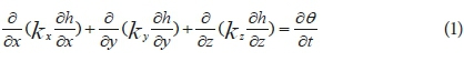
In which, h is the soil water head, kx, ky and kz represent the soil's hydraulic conductance in the x, y and z directions, respectively, and ϴ denotes the volumetric water content.
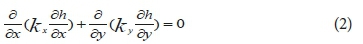
For steady-state conditions with no change in the volumetric water content, Eq. 1 is rewritten for 2-D flow as follows:
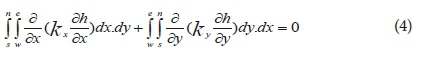
In this study, the control volume method has been employed in order to discretize the differential of Eq. 2 (Versteeg and Malalasekera, 2007). The finite volume method (FVM) is a very popular method for solving partial differential equations. The finite volume method shows a good response and is easy to implement in anisotropy, non-homogeneous material, and discontinuous boundaries. The finite volume method is as easy as finite difference and as powerful as finite element and is easy to program and implement (El-Jumaily and Jaber Al-Bakry, 2013). In addition, equations are presented in an integral form, which is often how they are derived from the underlying physical laws. Therefore, there is no need for dependent variables to be differentiable everywhere, which means that a larger class of problems can be solved. Integrating Eq. 2 on the control volume shown in Fig. 1 results in:
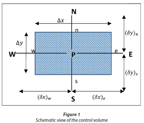
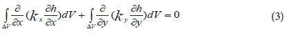
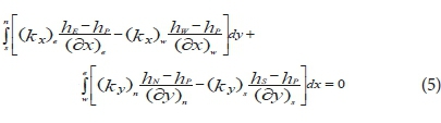
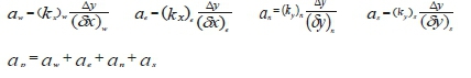
By considering a control volume of unit thickness, surface control areas of the control volume are Ae = Aw = ∆y and An = As = ∆x, this tends to:
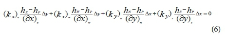
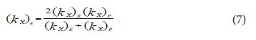
The finite volume method satisfies the continuity equation automatically so that each term of Eq. 6 represents the flow discharge entering and/or exiting each side of the control volume, in which, for example, (kx)e is the permeability coefficient on the eastern side of the control volume in Fig. 1, and, in this study, is considered as the average harmonic permeability coefficient of points P and E as follows:
Equation 6 can be rearranged and rewritten as follow:

where
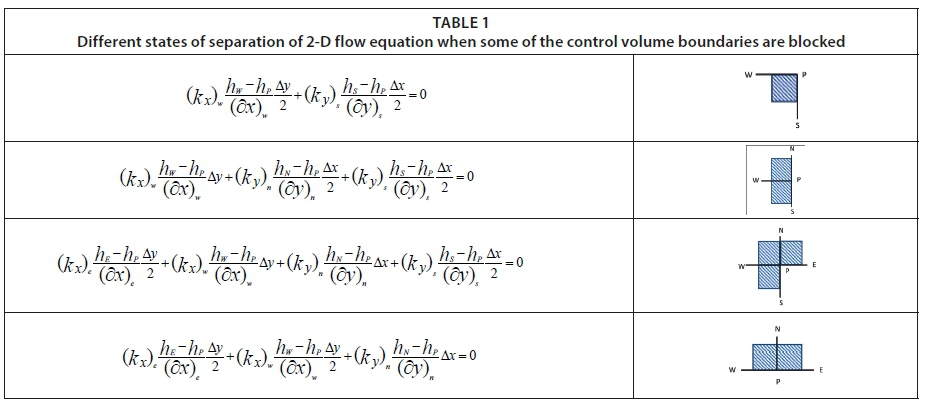
Under conditions where the central point of the control volume is located on one of the impermeable boundaries, on the domain corner, cut-off wall, etc., Eq. 6 needs to be discretized specifically, where only four of several available forms of their algebraic equations are given in Table 1.
Computational field and boundary conditions
The study area is shown in Fig. 2. In order to investigate the effect of the foundation slope on the seepage characteristics, the slope of the line between points 'h' and 'i' in Fig. 2 varies from −15% to +15% with a 2.5% increase. Fig. 2a shows the schematic view of the study area with downhill foundation slope and Fig. 2b shows it with uphill foundation slope. In addition, in order to evaluate the effect of the foundation slope in the presence of a cut-off wall, a cut-off wall with different lengths, ranging from zero to 6 m (adding 1 m at a time), is placed at the upstream end of the dam.

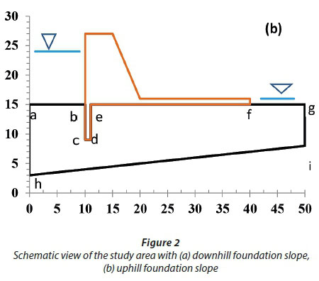
Other geometry characteristics of this study area, in addition to different types of boundary conditions are presented in Table 2.
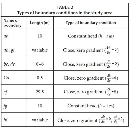
It can be noted from Table 2 that there are two types of boundary conditions in the study area: constant head boundary condition for ab and fg boundaries and zero-gradient boundary condition for other boundaries.
Physical model characteristics
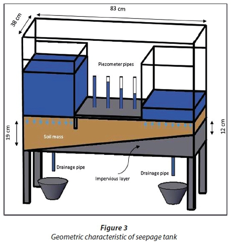
In order to obtain the measured data for mathematical model validation, a seepage tank with 38 cm width, 83 cm length and 80 cm height was made of 10-mm reinforced glass and installed on metal supports (Fig.3). A thin metal plate with 40 cm length and 38 cm width was put in the seepage tank, above the soil mass, as a dam base model. In addition, another thin metal plate with 10 cm length and 38 cm width was installed at the upstream end of the dam base as a cut-off wall. The distance of the cut-off from the left wall of the seepage tank was 23 cm. The thickness of the soil mass above the impervious layer is 19 cm and 7 cm in the vicinity of the left and right walls of the seepage tank, respectively. Therefore, as can be seen from Fig.3, the model's foundation slope is about +14.46%. In order to measure the uplift pressure, 4 piezometers were installed on a horizontal metal plate and 2 drainage pipes were installed on both sides of the tank near the lateral walls, to adjust the upstream and downstream water level. In order to keep the upstream water level constant (left side of tank in Fig.3), the amount of water that inflows to the tank, during the experiments, is more than the seepage discharge. The right drainage pipe shows the amount of seepage discharge from the soil mass.
RESULTS
Model verification using the measured data
Verification of the present model was carried out by measuring the value of seepage discharge and pressure head through performing 2 experimental tests. In the first test, the aim was to obtain the soil's permeability coefficient. For this purpose, the water depth was fixed at 24.3 cm and 7.3 cm, upstream and downstream of the dam model, respectively. The value of the seepage discharge was obtained equal to Qm = 6.909 × 10⁻⁷ through measurement of the flow exiting from the downstream end of the drainage pipe, volumetrically. Then, according to the first test's results, the numerical model was run for various permeability coefficients until Qc and Qm became equal. Ultimately, the value of the permeability of soil mass inside the tank was calculated at k = 5.3 × 10⁻⁵ m/s.
In the second experiment, the water depth was set at 23 cm, upstream of the dam model, and the process was repeated for the value of permeability obtained from the first test. The verification results have been summarized and presented in Table 3.
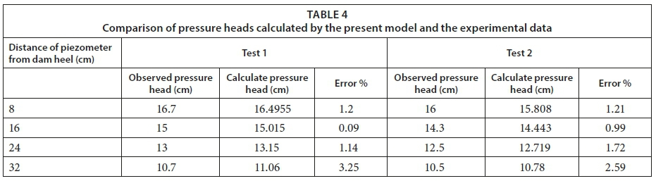
In order to compare the calculated pressure head with the experimental data, 4 piezometers were placed on metal plates, with 8 cm distance between the piezometers. Table 4 presents the observed and calculated pressure head for piezometers located at different distances from the dam heel as well as the model's errors.
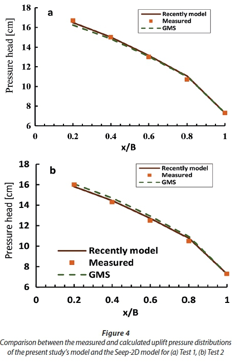
Table 4 indicates that the model's calculated seepage discharge has 3.48% and 3.79% error compared to the measured data in Test 1 and Test 2, respectively. In addition, comparison between the measured and calculated uplift pressure in Table 4 shows that the model can calculate the uplift pressure with a maximum error of less than 3.25%. For a complex phenomenon such as water flow in soil, the mentioned errors are negligible and the developed model's output is reliable for continuing the research. Also, the results of the present model have been compared with the results of Seep-2D model in the famous GMS commercial model package. The comparison between the distributions of the measured and calculated uplift pressures of the recent model and the Seep-2D model are shown in Fig. 4, which clearly indicates that the values of the calculated pressures by both models are very close to each other and also close to the measured value.
The effects of foundation slope on uplift pressure
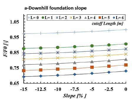
After ensuring the model's ability to simulate the water flow in soil and calculating the uplift pressure, the effects of the foundation slope on the uplift pressure force and seepage discharge were studied. Figure 5 shows the effect of the foundation slope on the non-dimensional uplift force. The uplift force has been rendered non-dimensional by dividing it by the uplift force of a non-slope, non-cut-off condition (base case), for different cut-off lengths. Figure 5a indicates that by increasing the downhill foundation slope (DFS) the uplift force decreases. By increasing the uphill foundation slope (UFS) from zero to 15%, the uplift pressure force increases 2.8% and 5.2% for the case without cut-off wall and for cut-off wall with 6 m length, respectively. Figure 5b also shows that by increasing the downhill foundation slope from zero to −15%, the uplift pressure force decreases 6% and 10.54% for the case without cut-off wall and with cut-off wall of 6 m length, respectively. In addition, for the same range of foundation slopes (0-15%), UFS is more effective in varying uplift pressure force compared to DFS. Moreover, Fig. 5 clearly demonstrates that as the cut-off wall's length increases the effect of DFS on decreasing, and UFS on increasing, the uplift pressure force becomes more severe.
The effects of the foundation slope on seepage discharge
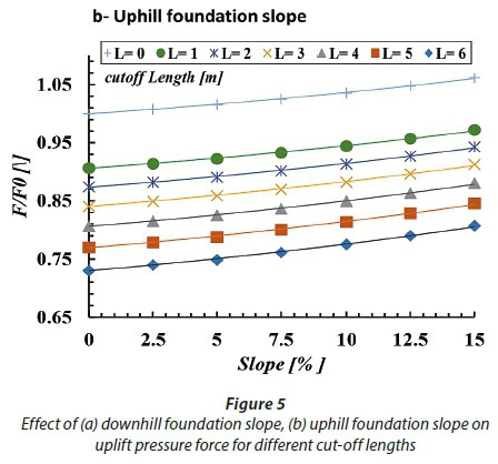
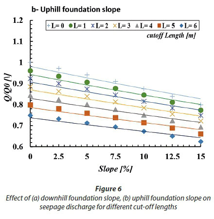
The effect of the foundation slope on seepage discharge, for different cut-off lengths, is shown in Fig. 6. It should be noted that all seepage discharges have been rendered non-dimensional by the seepage discharge of the base case (Q0). Figure 6a shows that for all cut-off wall lengths, by increasing the DFS the seepage discharge increases. For the condition without cut-off wall, by increasing the DFS from zero to −15% the seepage discharge increases 11.32%. However, for the case with a 6 m cut-off wall and for the same variation in the DFS, the seepage discharge increases 10.42%. Figure 6b also indicates that, for all cut-off wall lengths, by increasing the UFS, the seepage discharge decreases. In the case with no cut-off wall (L = 0), by increasing the UFS from zero to 15%, the seepage discharge decreases about 20% while for L = 6 m it decreases about 17.3%. For the same variation in the foundation slope (0-15%), the effect of UFS in decreasing the seepage discharge is more than the effect of DFS on increasing the seepage discharge. As a result, UFS is more effective than DFS on the variation of seepage discharge. In addition, Fig. 6 indicates that by increasing the cut-off wall's length, the effect of DFS on increasing the seepage discharge and the effect of UFS on decreasing the seepage discharge become milder.
The effects of the foundation slope on uplift pressure distribution
The distribution of uplift pressure under the dam structure, for different foundation slopes, is shown in Fig. 7. It can be seen that the uplift pressure under the dam structure for DFS is smaller than UFS. In addition, at each point the extra pressure because of UFS is more than the deficit pressure because of DFS. The effect of the foundation slope on the uplift pressure decreases from the upstream end of the dam towards the downstream end of dam, so that at the downstream end of the dam, all slopes show the same uplift pressure.
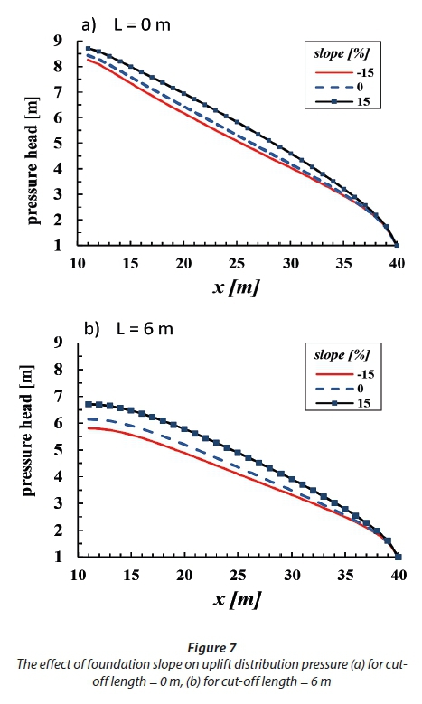
Comparison between Fig. 7a and Fig. 7a indicates that regardless of the foundation slope, the existence of a cut-off wall at the upstream end of the dam reduces the uplift pressure compared to the case with no cut-off wall.
The effect of the foundation slope on the exit gradient
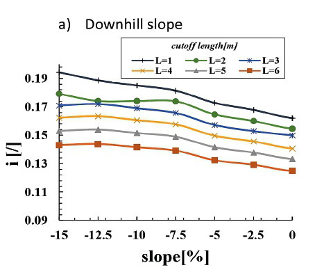
Figure 8 shows the effect of foundation slope on the exit hydraulic gradient. Figure 8a readily demonstrates that DFS directly affects the exit gradient so that by increasing the DFS, the exit gradient also increases. Although, in the study area of this research, the exit gradient is less than unity for all foundation slopes. Nevertheless, in the case where the exit gradient is close to unity (critical gradient), ignoring the effect of DFS can threaten the stability of the dam structure. For 1 m and 6 m cut-off lengths, by increasing the foundation slope from zero to −15%, the exit gradient increases 19.75% and 14.4% respectively. In addition, Fig. 8b shows that by increasing the UFS from zero to 15% the exit gradient decreases for all cut-off lengths. For instance, for L = 0.0 m and L = 6 m the exit gradient decreases 25.92% and 24%, respectively. Comparison between Fig. 8a and Fig. 8b indicates that, for the same cut-off lengths, the exit gradient in UFS is less than DFS. Moreover, by increasing the cut-off length, the exit gradient decreases, but its effect on the decrease of the exit gradient in DFS is more than UFS.

CONCLUSION
In the present study a numerical model was developed, in which a general equation of fluid flow in non-uniform, anisotropic soil is solved by the finite volume method on a structured grid. The model was successfully validated using experimental data and was applied to analyse the effect of downhill and uphill foundation slopes on the seepage characteristics under the hydraulic structure. The foundation slope varied from zero to 15% in the uphill and downhill directions. The results indicated that by increasing the downhill foundation slope (DFS) from zero to 15%, the uplift pressure force decreases 2.8% and 5.2% for cut-off lengths L = 0 and L = 6 respectively and for the same increase in the uphill foundation slope (UFS) the uplift pressure force increases 6% and 10.54% for L = 0 and L = 6 m respectively. For the same variation of foundation slope (0−15%), UFS is more effective on the uplift pressure force compared to DFS. In addition, for a constant cut-off length, the uplift pressure under the dam for DFS is smaller than UFS.
By increasing the DFS from zero to 15%, the seepage discharge increases for all cut-off wall lengths, for example the seepage discharge increases 11.32% and 10.42% for L = 0 m and L = 6 m, respectively. In addition, increasing the UFS decreases the seepage discharge for all cut-off wall lengths. For example, the seepage discharge decreases 20% and 15% for L = 0 and L = 6 m, respectively. The exit gradient of UFS is less than DFS for the same cut-off lengths. Moreover, by increasing the cut-off length, the exit gradient decreases. However, its effect on the reduction of the exit gradient in DFS is more than UFS.
REFERENCES
ASADI SAKHMARSI A, AKHBARI H, NAEIMI SP and KIAPEY A (2014) The effect of the cut-off wall conditions on the seepage characteristics of homogeneous earth-fill dams using SEEP/W. WALIA J. 30 (S2) 176−182. [ Links ]
AZIZI S, SALMASI F, ABBASPOUR A and ARVANAGHI H (2012) Weep hole and cut-off effect in decreasing of uplift pressure (case study: Yusefkand Mahabad Diversion Dam). J. Civ. Eng. Urbanism 2 (3) 97−101. [ Links ]
Al TABATABAIE FA and AL WAHILY DS (2017) The effect of impervious layer depth on the uplift water pressure beneath the gate location in the hydraulic structures. Sci. J. Cihan Univ. Sulaimanyia 1 (4) 11−23. [ Links ]
BAGHALIAN S and NAZARI F (2011) prediction of uplift pressure under the diversion dam using artificial neural network and genetic algorithm. Int. J. Eng. Appl. Sci. 3 (3) 23−32. [ Links ]
DAS B M (2008) Advanced Soil Mechanics (3rd edn). Taylor & Francis, New York. [ Links ]
EL-JUMAILY KK and JABER AL-BAKRY HM (2013) Seepage analysis through and under hydraulic structures applying finite volume method. Eng. Technol. J. 31 (9) 1719−1729. [ Links ]
FADEL ALSENOUSI KH and MOHAMED H (2008) Effects of inclined cut-offs and soil foundation characteristics on seepage beneath hydraulic structures. Twelfth International Water Technology Conference, IWTC12, Alexandria, Egypt. 1598−1617. [ Links ]
GHOBADIAN R and KHODAEE K (2009) Effects of cut-off wall and drain on uplift pressure and exit gradient under hydraulic structure by numerical solution of general equation of fluid flow in soil using finite volume method. J. Water Soil Iran 23 (4) 148−160 (in Persian). [ Links ]
GRIFFITHS DV and FENTON GA (1997) Three-dimensional seepage through spatially random soil. J. Geotech. Geoenviron. Eng. 123 (2) 256−262. https://doi.org/10.1061/(ASCE)1090-0241(1997)123:2(153) [ Links ]
HUSSEIN NEJAD BELKO MH, SHAKERIAN S, HAGHI ABI A and TURABI PODEH H (2014) Simulation of flow from under the Diversion Dam and cut-off wall effects with finite volume method. The first national e-conference on Advances in Basic Sciences and Engineering, August 2014. 136−144. [ Links ]
JELENKOVI T and TRAVAŠ V (2013) Numerical and experimental analysis of seepage beneath a model of a gravity dam. Eng. Rev. 33 (2) 75−84. [ Links ]
LASHTEH NESHAEI SA, MEHRDAD MA and ABEDI MAHZOON N (2010) Optimum design of cut off walls located in the foundation of diversion dams using boundary element method. In: Brebbia CA (ed.) Boundary Elements and Other Mesh Reduction Methods XXXII. Transactions on Modelling and Simulation. Wessex Institute of Technology, UK, Transaction 50. 53-61. [ Links ]
KHALILI SHAYAN H and AMIRI-TOKALDANY E (2015) Effects of blanket, drains, and cut-off wall on reducing uplift pressure, seepage, and exit gradient under hydraulic structures. Int. J. Civ. Eng. 13 (4A) 486−500. [ Links ]
KHAN B, AMIN M and BADSHAH N (2013) Evaluation of different seepage control measures for a proposed "GOLEN GOL" weir in Pakistan. Sci. Tech. Dev. 32 (4) 299−307. [ Links ]
MANSURI B and SALMASI F (2013) Effect of horizontal drain length and cut-off wall on seepage and uplift pressure in heterogeneous earth dam with numerical simulation. J. Civ. Eng. Urbanism 3 (3) 114−121. [ Links ]
MANSURI B, SALMASI F and OGHATI B (2014) Effect of location and angle of cut-off wall on uplift pressure in diversion dam. Geotech. Geol. Eng. 32 (5) 1165-1173. https://doi.org/10.1007/s10706-014-9774-3 [ Links ]
MOHARRAMI A, MORADI GH, HAJIALILUE BONAB M, KATEBI J and MOHARRAMI GH (2014) performance of cut-off walls under hydraulic structures against uplift pressure and piping phenomenon. Geotech. Geol. Eng. 33 (1) 95−103. https://doi.org/10.1007/s10706-014-9827-7 [ Links ]
SALIM ALGHAZALI NO and TAEH ALNEALY HK (2015) Analysis the seepage under the hydraulic structure putted in single layer soil by using the hydraulic modeling method. Int. J. Sci. Technol. Res. 4 (4) 2277−8616. [ Links ]
SEDGHI-ASL M, RAHIMI H and KHALEGHI H (2005) Effect of cut-off wall's depth and situation on reducing seepage under hydraulic structures by using numerical method. Fifth Iranian Hydraulic Conference, Kerman University (in Persian). [ Links ]
VERSTEEG H K and MALALASEKERA W (2007) An Introduction to Computational Fluid Dynamics − the Finite Volume Method. Pearson Education Limited. 503 pp. [ Links ]
ZAINAL EAK (2011) The effects of cut-off wall angle on seepage under dams. J. Eng. 17 (5) 1109−1131. [ Links ]
ZOORASNA Z, HAMIDI A and GHANBARI A (2008) Seepage through different concrete cut off wall connection systems Case Study: Karkheh Storage Dam. 6th International Conference on Case Histories in Geotechnical Engineering, 11-16 August 2008, Arlington, Virginia. [ Links ]
Received 24 November 2017
Accepted in revised form 4 December 2018.
* To whom all correspondence should be addressed. e-mail: Rsghobadian@gmail.com

