


Services on Demand
Article
 English (pdf)
 Article in xml format
 Article references
Indicators

Related links
-
 Cited by Google
 -
 Similars in Google
Share

 Permalink
Water SA
On-line version ISSN 1816-7950
Print version ISSN 0378-4738
Water SA vol.43 n.3 Pretoria Jul. 2017
http://dx.doi.org/10.4314/wsa.v43i3.02
Experimental evaluation of helically coiled tube flocculators for turbidity removal in drinking water treatment units
Danieli Soares de OliveiraI, *; Edmilson Costa TeixeiraII
IIFES - Federal Institute of Espírito Santo, Rodovia G. José Sette S/N Itacibá, Campus Cariacica, Cariacica-ES 29150-410, Brazil
IIUFES - Federal University of Espírito Santo, Av. Fernando Ferrari, S/N Goiabeiras, Vitória-ES 29075-910, Brazil
ABSTRACT
The constant need to improve water treatment techniques allows for the emergence of new technologies for obtaining adequate water, both in terms of quality and quantity. In order to obtain an efficient, rapid and low-cost clarification system, this study proposes the use of helically coiled tubes (HCTs) as a coagulation-flocculation reactor coupled with a conventional decanter system. Eighty-four (84) turbidity removal tests were performed to evaluate the proposed clarification system, while varying hydraulic and geometrical parameters in HCTs. Removal efficiency values higher than 80% were obtained (with a maximum removal efficiency of 86.2%), presenting better results than systems using baffled tanks, which are traditionally applied for water treatment purposes in developing countries. In addition, significantly lower processing times (lower than 2 min, about 10% of baffled tank processing times) were observed for high efficiency process values, indicating that this clarification system can be useful in rational design of coagulation-flocculation units. It should be noted that the turbidity removal efficiency results obtained (with a rising-then-decreasing behaviour over time) differ significantly from those obtained by the commonly used models for flocculation evaluation (with asymptotic behaviour over time), presenting a maximum absolute percentage deviation of 48.9%, and indicating caution in the use of such models for alternative flocculation unit evaluation.
Keywords: flocculation, drinking water, turbidity, turbidity removal efficiency, helically coiled tubes
INTRODUCTION
Suspended solids removal is an essential component of drinking water treatment. Such removal is commonly done in three steps which together comprise the clarification process: coagulation, flocculation and sedimentation/flotation.
Coagulation involves the dispersal of a coagulant into the mass flow by an intense agitation, usually measured by G, the mean velocity gradient, and producing particle destabilisation. After that, the destabilised particles are submitted to weak agitation to promote floc formation; this step is called flocculation. At the end, the flocs are separated from the water by sedimentation/flotation.
There are interesting studies dealing with the effect of G on the size and structure of flocs formed during destabilisation/aggregation (e.g., Bubakova and Pivokonsky, 2012; Lin et al., 2013; Polasek, 2007; Spicer et al., 1998). Furthermore, some studies evaluate the hydrodynamic behaviour in flocculators, aiming to better understand the process (Haarhoff and Van Der Walt, 2001; Sartori et al., 2015).
In developing countries it is common to use hydraulic flocculators, which promote agitation in water by imposing direction changes on the mass flow (Liu et al., 2004). Local velocity gradients caused by the sudden changes of direction can promote disruption of the flocs previously formed, reducing the efficiency of the process.
In this context, several authors have suggested the use of helically coiled tubes to promote flocculation without abrupt changes in the direction of flow, but rather with smooth changes of direction throughout the unit (Al-Hashimi and Ashjyan, 1989; Elmaleh and Jabbouri, 1991; Gregory, 1981; Grohmann et al., 1981; Hameed et al., 1995; Thiruvenkatachari et al., 2002; Tse et al., 2011; Vaezi et al., 2011; Vigneswaran and Setiadi, 1986). These studies have shown that this flocculator, called the 'helically coiled tube flocculator - HCTF', promotes efficient floc formation with high velocity gradient values (due to its helical characteristic - with high head loss values) and low process times. Furthermore, HCTF is an easy-to-clean, low-cost and compact system, indicating that it is a good alternative for solid-liquid separation in the expansion of already existing units or in new drinking water facilities.
As an example, the flocculation time needed to have a residual turbidity under 5% in a baffled channel hydraulic flocculator is about 15-20 min for Q = 1.8 m3/h (McConnachie and Liu, 1999). Meanwhile, in a HCTF, about 1 min is needed to achieve the same residual turbidity, considering Q = 0.7 m3/h (Grohmann et al., 1981). This result emphasises the importance of evaluating the use of helically coiled tubes as flocculators in order to improve the clarification process.
Despite the large field of work already published, there is still a need for further experimental studies of the efficiency of turbidity removal in drinking water. In particular, the mathematical models commonly used to examine coagulation and flocculation processes (Argaman and Kaufman, 1970; Bratby et al., 1977; Camp and Stein, 1943; Fair and Gemmell, 1964; Harris et al., 1966; Schuetz and Piesche, 2002; Smoluchowski, 1917) have not yet been tested in this kind of treatment unit.
This paper presents and analyses the experimental results for turbidity removal efficiency and processing time of a clarification system composed of a helically coiled tube flocculator (as a coagulation-flocculation reactor) coupled to a conventional decanter system, applied to water treatment systems. Furthermore, this study evaluates two mathematical models commonly used to estimate flocculation performance in order to recommend a tool for rational design of units for practical purposes.
MATERIALS AND METHODS
The methodology proposed in this study was divided into five parts: first, the experimental modelling apparatus is shown and described. After that, details of the reactor set-ups and the decanter system are described. and the main flocculation parameters used in this research are presented. Finally, the mathematical models commonly used to measure flocculator efficiency are described.
Experimental modelling apparatus
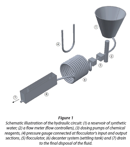
The experimental apparatus used is shown in Vigneswaran and Setiadi (1986), based on a complete cycle of the clarification system, composed of: (1) a reservoir of synthetic water; (2) a flow meter (flow controllers), (3) dosing pumps of chemical reagents, (4) pressure gauge connected at flocculator's input and output sections, (5) flocculator, (6) decanter system (settling tank) and (7) drain to the final disposal of the fluid.
Initially, water is pumped and mixed with clay (bentonite), resulting in a synthetic water. A mixer operates continuously to ensure that fluid characteristics are kept uniform, with pH and temperature values approximately equal to 6.0 and 22°C, respectively. At the end of mixing, the effluent had an average turbidity of 50 UT, considered to be the initial turbidity value in all tests. After that, the flow rate is measured, and the coagulant (aluminium sulphate, for destabilisation of the particles) and alkalising agent (sodium hydroxide, for pH adjustment) are added by the dosing pumps located upstream of the flocculator. After the addition of these chemicals, the fluid passes through the flocculator (where head loss was measured in all tests) and goes to the settling tank, where sample collection took place in order to determine the final turbidity. The final disposal of the fluid is made at the end drain. The experimental uncertainty based on instrumental uncertainty was 10%.
Reactor set-up
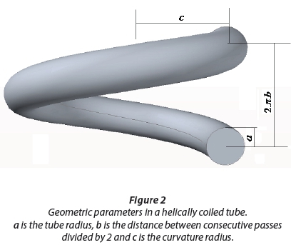
HCTF consists of a transparent and flexible polyvinyl chloride hose (PVC hose), coiled in a rigid PVC pipe. The hose used has a smooth internal surface with synthetic yarn reinforcement giveing high tenacity to ensure that there are no changes in the cross section along the reactor. The main features of the reactor are described in Figure 2.
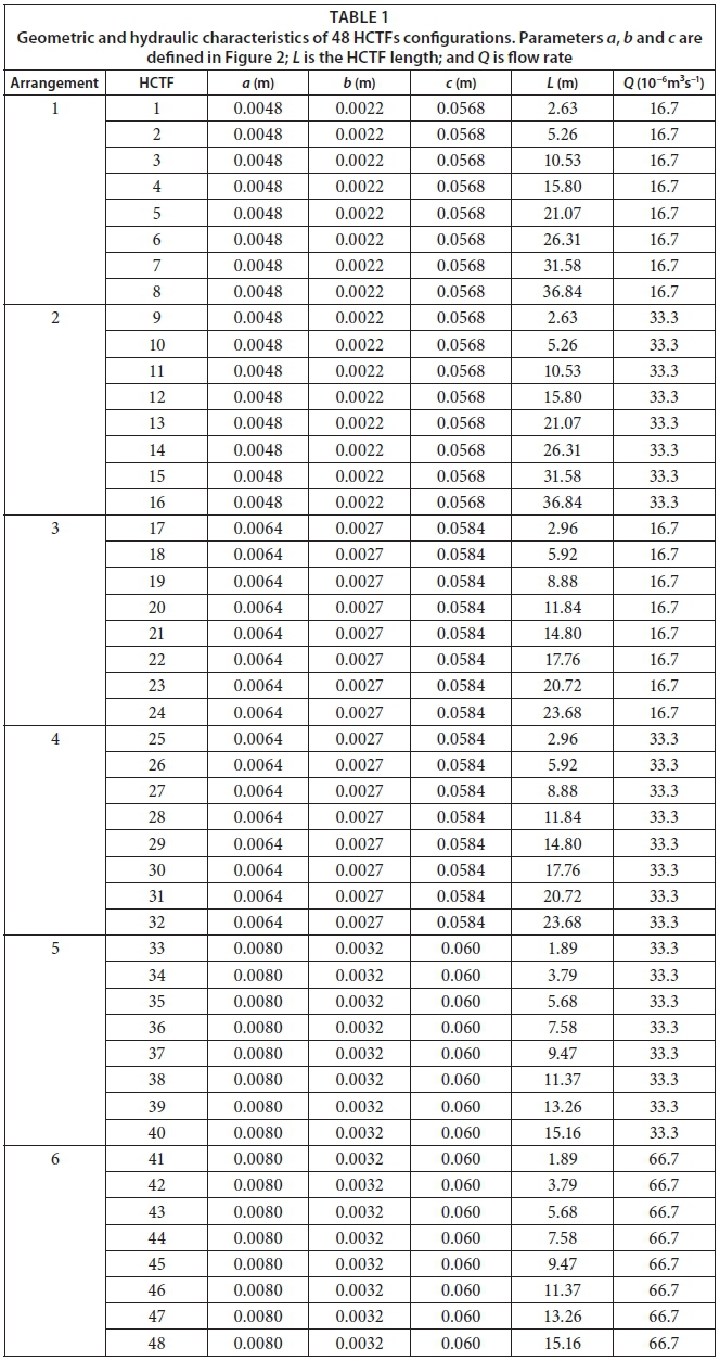
Forty-eight (48) HCTF configurations were tested (24 HCTFs with two different flow rates), and their characteristics are described in Table 1. Six different arrangements are verified, and the distinguishing parameter is the reactors' length and, therefore, the flocculation process time.
Decanter system
In order to evaluate the solid liquid separation and the turbidity removal efficiency, each HCTF was coupled to a single settling tank, as shown in Fig. 3.
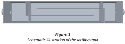
To ensure that the geometric and hydraulic features of the decanter do not hinder the final turbidity removal efficiency of the process, a single decanter (with the same flow rate) was used in all experiments. The sedimentation velocity used in all tests was 0.21 cm/s, according to Di Bernardo and Dantas (2005).
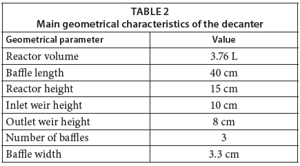
The decanter design was based on retention time, flow velocity and input/output devices, following the methodology described by Di Bernardo and Dantas (2005). The material used for outside walls was polystyrene and the baffles were built with plastic sheets 1.5 mm thick. Table 2 shows the main geometrical characteristics of the decanter.
Main flocculation parameters
This section presents the main flocculation parameters used (Table 3) The Reynolds number was calculated to characterise flow regimes - in all cases flow was laminar (Cioncolini and Santini, 2006; Oliveira and Teixeira, 2016).
Mathematical models
In general, flocculation is commonly measured by the use of mathematical models which consider hydraulic parameters and water quality information. There is no specific model given in the literature to evaluate flocculation in HCTFs. Therefore, in this study, Argaman and Kaufman (1970) and Bratby et al. (1977) models (Equations 1 and 2, respectively) were evaluated due to their extensive utilisation in unit design (Haarhoff et al., 1996; Moruzzi and Oliveira, 2012).
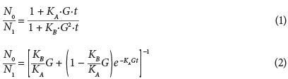
where: N0 and N1 are initial and final concentrations, respectively (in this paper initial and final concentrations are represented by initial and final turbidity values - as presented in Bratby et al. (1977)). KA and KB are constants obtained from experimental results and Equations 1 and 2, considering the values of N1 and t related to the maximum value of the experimental curve (where dN1/dt = 0). Based on values of KA, KB, N0 and G (constants), a relationship between N1 and t is obtained.
RESULTS AND DISCUSSION
First, the coagulation diagram results are shown and described. After that, the experimental results for turbidity removal efficiency and processing time of HCTFs are presented and analysed. Finally, two mathematical models were used together to estimate flocculation performance.
Coagulation diagram
A coagulation diagram was used to select the appropriate coagulant dosage for a given application. Thirty-six (36) tests were performed in order to build the coagulation diagram, shown in Fig. 4.
From Fig. 4, one can note that the values for turbidity removal efficiency varied in the range 1%-98%. Furthermore, 60% of the tests gave values for turbidity removal efficiency higher than 80%, with 43% of tests giving a turbidity removal efficiency higher than 90%, indicating a remaining turbidity of less than 5 UT.
In the performed tests, the coagulant and alkalising dosages were chosen based on three criteria: (i) minimise the use of chemical agents; (ii) the pH of the final solution should be near to that recommended in the literature (from 6 to 8); and (iii) the chemical dosages should allow the solution to be sensitive to variations in HCTF geometrical characteristics.
Based on these criteria, the operational point was chosen, considering a dosage of aluminium sulphate equal to 40 mg/L and a dosage of sodium hydroxide equal to 50 mg/L. This operational point presented a turbidity removal efficiency equal to 82%, given an initial turbidity of 50 UT (highlighted in red in Fig. 4). The pH of the final solution was equal to 6.8 and the remaining turbidity was equal to 9.4 UT. These dosages of aluminium sulphate and sodium hydroxide were kept unchanged for all of the performed analyses.
HCTF experimental results
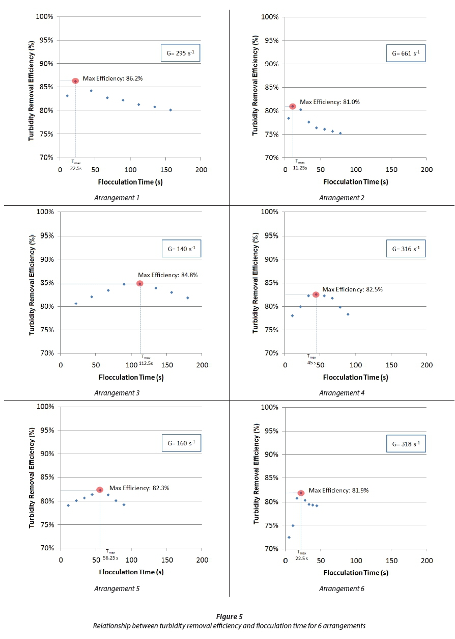
The experimental modelling results obtained for the 48 HCTF configurations are shown in Fig. 5. The results for turbidity removal efficiency versus flocculation time are shown for the six studied arrangements defined in Table 1. In addition, the mean velocity gradient results, maximum turbidity removal efficiency value and respective process time are shown in Fig. 5. The mean error value for turbidity removal efficiency measurements was 1.5%.
From Fig. 5, the values of turbidity removal efficiency have a rising-then-decreasing behaviour with increase in HCTF flocculation time. With this, maximum turbidity removal efficiency regions may be verified for specific process times, and such process times are dependent on units' hydraulic and geometric parameters. These parameters influence the hydrodynamic behaviour of the unit, which strongly affects the interaction between particles present in a liquid mass. This interaction is favoured in helically coiled tubes, whereas the presence of a secondary flow in cross section promotes a major interaction between particles previously destabilised, favouring the formation of flocs (Sartori et al., 2015). However, the flow's behaviour can promote destabilisation in flocs previously formed due to the shear stresses verified in helical flows, reducing the efficiency of the process over time.
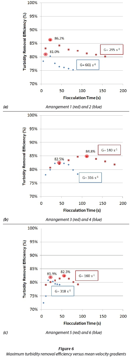
When the maximum turbidity removal efficiency is evaluated with mean velocity gradients (considering the same geometric characteristics and different flow rates), one notes that the best results were obtained for the lowest mean velocity gradient values (Fig. 6). These results show that higher velocity gradient values and, consequently, higher shear stress values, can promote a decrease in the efficiency of the process. For the cases evaluated in this study, the increase in the mean velocity gradient is exclusively due to the increase in flow rate, whereas the other characteristics were held constant. This result confirms that changes in flocculation unit flow should be evaluated with caution, since these changes can significantly influence the interaction between the particles and consequently in solid-liquid separation.
The rising-then-decreasing behaviour verified for turbidity removal efficiency with increase in HCTF flocculation time is not verified in mathematical models commonly used to estimate the relationship between initial and final turbidity. In particular, models presented in Argaman and Kaufman (1970) and Bratby et al. (1977) (described in Materials and Methods), have an asymptotic characteristic, shown in Appendix 1.
In order to analyse such models, as applied to HCTFs, Fig. 7 presents the results obtained for Arrangement 2 (Table 1: HCTF 9 to HCTF 16) in a dimensionless form (the process time was normalised using maximum process time).
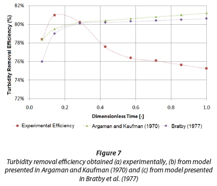
It can be noted in Fig. 7 that the functions evaluated deviate considerably from the values obtained experimentally. In addition, from the evaluation of other configurations tested in this study, the maximum and average percentage deviations values can reach 48% and 27%, respectively, as shown in Table 4.
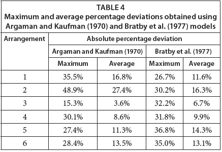
Results obtained from models presented in Argaman and Kaufman (1970) and Bratby et al. (1977) can be qualitatively and quantitatively evaluated. Quantitatively, a significant deviation is observed in the maximum absolute percentage deviation values (since experimental uncertainty is 10%). Therefore, the average absolute percentage deviation values were not acceptable in most cases. Qualitatively, the asymptotic characteristic observed in Fig. 7 differs significantly from the rising-decreasing behaviour experimentally verified, indicating that these models are not adhering to the assessed physical process. Thus, there is a need to obtain models that can adequately predict the behaviour of values for turbidity removal efficiency in HCTFs, since in both cases the models tested were not adequate to estimate flocculation process efficiency.
CONCLUSION
The use of helically coiled tubes as a coagulation-flocculation reactor coupled to a conventional decanter system was evaluated experimentally in this study, with the aim of water clarification. A rising-then-decreasing behaviour was verified for turbidity removal efficiency with the increase in HCTF flocculation time, indicating that it is possible to obtain maximum-removal turbidity efficiency values for specific reactor characteristics. Removal efficiency values higher than 80% were obtained (with a maximum removal efficiency value of 86.2%), presenting better results than systems using baffled tanks, which are traditionally applied for water treatment purposes in developing countries. Additionally, significantly lower processing times (lower than 2 min, about 10% of baffled tank processing times) were observed for high efficiency process values, indicating that this kind of flocculator can be promising for use in clarification processes. Also, it was verified that the most efficient results were obtained for the HCTFs with lowest mean velocity gradients, indicating that higher velocity gradients and, consequently, higher shear stress values, result in decreases in efficiency. Lastly, two mathematical models extensively used in unit design - Argaman and Kaufman (1970) and Bratby et al. (1977) - were evaluated and did not present good results (showing a maximum absolute percentage deviation of 48.9%). This suggests the need for development of a non-asymptotic model that can satisfactorily estimate the rising-then-decreasing efficiency behaviour over time.
ACKNOWLEDGMENTS
The authors would like to thank the institutional and financial support from Federal Institute of Espírito Santo (IFES), Federal University of Espírito Santo (UFES), Coordination for the Improvement of Higher Education Personnel (CAPES) and National Counsel of Technological and Scientific Development (CNPq).
REFERENCES
AL-HASHIMI MAI and ASHJYAN ASK (1989) Effectiveness of helical pipes in the flocculation process of water Filtr. Sep. 26 (6) 422-429. [ Links ]
ARGAMAN Y and KAUFMAN WJ (1970) Turbulence and flocculation. J. Sanit. Eng. Div. Proc. Am. Soc. Civ. Eng. 96 (SA 2) 223-241. [ Links ]
BRATBY J, MILLER MW and MARAIS GR (1977) Design of flocculation systems from batch test data. Water SA 3 (4) 173-182. [ Links ]
BUBAKOVA P and PIVOKONSKY M (2012) The influence of velocity gradient on properties and filterability of suspension formed during water treatment. Sep. Purif. Technol. 92 161-167. https://doi.org/10.1016/j.seppur.2011.09.031 [ Links ]
CAMP TR and STEIN PC (1943) Velocity gradients and internal work in fluid motion. J. Boston Soc. Civ. Eng. 30 219-237. [ Links ]
CIONCOLINI A and SANTINI L (2006) An experimental investigation regarding the laminar to turbulent flow transition in helically coiled pipes. Exp. Therm. Fluid Sci. 30 367-380. https://doi.org/10.1016/j.expthermflusci.2005.08.005 [ Links ]
DI BERNARDO L and DANTAS ADB (2005) Water Treatment Methods and Techniques. (In Portuguese.) RIMA, São Paulo. [ Links ]
ELMALEH S and JABBOURI A (1991) Flocculation energy requirement. Water Res. 25 (8) 939-943. https://doi.org/10.1016/0043-1354(91)90141-C [ Links ]
FAIR GM and GEMMELL RS (1964) A mathematical model of coagulation. J. Colloid Sci. 19 360-372. https://doi.org/10.1016/0095-8522(64)90037-6 [ Links ]
GREGORY J (1981) Particle interactions in flowing suspensions. Adv. Colloid Interface Sci. 17 (1) 149-160. https://doi.org/10.1016/0001-8686(82)80016-X [ Links ]
GROHMANN A, REITER M and WIESMANN U (1981) New flocculation units with high efficiency. Water Sci. Technol. 13 (11/12) 567-573. [ Links ]
HAARHOFF J, VAN BEEK JC and VAN ZYL HJ (1996) Practical application of the Argaman-Kaufman flocculation model. In: Biennial Conference and Exhibition, Water Institute of Southern Africa, 20-23 May 1996, Port Elizabeth. [ Links ]
HAARHOFF J and VAN DER WALT JJ (2001) Towards optimal design parameters for around-the-end hydraulic flocculators. J. Water Suppl. Res. Technol.- AQUA 10 149-159. [ Links ]
HAMEED MS, MUHAMMED TJ and SAPRE AA (1995) Improved technique for river water flocculation. Filtr. Sep. 32 (2) 63-68. https://doi.org/10.1016/S0015-1882(97)84021-9 [ Links ]
HARRIS HF, KAUFMAN WJ and KRONE RB (1966) Orthokinect flocculation in water purification. J. Sanit. Eng. Div.; Proc. ASCE 92 (SA6) 95-111. [ Links ]
LIN J-L, PAN JR and HUANG C (2013) Enhanced particle destabilization and aggregation by flash-mixing coagulation for drinking water treatment. Sep. Purif. Technol. 115 145-151. https://doi.org/10.1016/j.seppur.2013.05.013 [ Links ]
LIU J, CRAPPER M and MCCONNACHIE GL (2004) An accurate approach to the design of channel hydraulic flocculators. Water Res. 38 875-886. https://doi.org/10.1016/j.watres.2003.10.014 [ Links ]
MCCONNACHIE GL and LIU J (1999) Design of baffled hydraulic channels for turbulence-induced flocculation. Water Res. 34 1886-1896. https://doi.org/10.1016/S0043-1354(99)00329-2 [ Links ]
MORUZZI R and OLIVEIRA S (2012) Mathematical modeling and analysis of the flocculation process in chambers in series. Bioprocess Biosyst. Eng. 36 (3) 357-363. https://doi.org/10.1007/s00449-012-0791-4 [ Links ]
OLIVEIRA DSD and TEIXEIRA EC (2016) Comparison between critical Reynolds number estimation models applied to helically coiled tubes flocculators. (In Portuguese.) In: XVII Luso-Brazilian Symposium on Sanitary and Environmental Engineering - SILUBESA, ABES, 6-8 June 2016, Florianópolis. [ Links ]
POLASEK P (2007) Differentiation between different kinds of mixing in water purification - back to basics. Water SA 33 (2) 249-252. [ Links ]
SARTORI M, OLIVEIRA DS, TEIXEIRA EC, RAUEN WB and REIS NC (2015) CFD modelling of helically coiled tubes for velocity gradient assessment. J. Braz. Soc. Mech. Sci. Eng. 37 (1) 187-198. https://doi.org/10.1007/s40430-014-0141-3 [ Links ]
SCHUETZ S and PIESCHE M (2002) A mathematical model of coagulation processes. Sep. Purif. Technol. 26 (1) 61-68. https://doi.org/10.1016/S1383-5866(01)00117-4 [ Links ]
SMOLUCHOWSKI M (1917) Versuch einer mathematischen Theorie der Koagulationskinetik kolloider Lösungen. Z. Phys. Chem. 92 129-168 [ Links ]
SPICER PT, PRATSINIS SE, RAPER J, AMAL R, BUSHELL G and MEESTERS G (1998) Effect of shear schedule on particle size, density and structure during flocculation in stirred tanks. Powder Technol. 97 (1) 26-34. https://doi.org/10.1016/S0032-5910(97)03389-5 [ Links ]
THIRUVENKATACHARI R, NGO HH, HAGARE P, VIGNESWARAN S and AIM RB (2002) Flocculation-cross-flow microfiltration hybrid system for natural organic matter (NOM) removal using hematite as a flocculent. Desalination 147 (1) 83-88. https://doi.org/10.1016/S0011-9164(02)00580-5 [ Links ]
TSE IC, SWETLAND K, WEBER-SHIRK ML and LION LW (2011) Method for quantitative analysis of flocculation performance. Water Res. 45 (10) 3075-3084. https://doi.org/10.1016/j.watres.2011.03.021 [ Links ]
VAEZI GF, SANDERS RS and MASLIYAH JH (2011) Flocculation kinetics and aggregate structure of kaolinite mixtures in laminar tube flow. J. Colloid Interf. Sci. 355 (1) 96-105. https://doi.org/10.1016/j.jcis.2010.11.068 [ Links ]
VIGNESWARAN S and SETIADI T (1986) Flocculation study on spiral flocculator. Water Air Soil Pollut. 29 (2) 165-188. https://doi.org/10.1007/bf00208407 [ Links ]
Received 13 March 2016
Accepted in revised form 26 May 2017
* To whom all correspondence should be addressed. +55 27 999050240-e -mail: danieli@ifes.edu.br
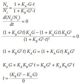
As an example, the asymptotic characteristic of Argaman and Kaufman (1970)'s model can be easily verified by an absence of inflection point in its equation:
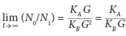
And a constant value for the ratio N0/N1 when lim 
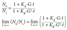
Appling L'Hôpital's rule:

