


Servicios Personalizados
Articulo
 Inglés (pdf)
 Articulo en XML
 Referencias del artículo
Indicadores

Links relacionados
-
 Citado por Google
 -
 Similares en Google
Compartir

 Permalink
Water SA
versión On-line ISSN 1816-7950
versión impresa ISSN 0378-4738
Water SA vol.37 no.2 Pretoria abr. 2011
Local energy losses at positive and negative steps in subcritical open channel flows
Nuray Denli Tokyay; A Burcu Altan-Sakarya*
Middle East Technical University, Department of Civil Engineering, 06531, Ankara, Turkey
ABSTRACT
Local energy losses occur when there is a transition in open channel flow. Even though local losses in subcritical open channel flow due to changes in channel width have been studied, to date no studies have been reported for losses due to changes in bed elevations. Steps are commonly used in engineering applications to stabilise the flow in open channels. Hence, it is important to estimate local losses for design purposes. The aim of this study was to formulate the local energy losses at positive and negative steps in subcritical open channel flows. Flow rates and water depths before and after the step were measured for varying step heights of abrupt and 45º inclined steps. Empirical equations relating the local losses to the Froude number on the step and the relative step height are proposed for positive and negative steps. In addition, practical values of local loss coefficients are determined.
Keywords: local (minor) loss, positive step, negative step, open-channel flow
Introduction
The energy losses that result from local features such as weirs, gates, cross-sectional changes or changes in alignment are called local or minor losses. Local losses may be computed as a fraction of the velocity head (Chow, 1959). This fraction is usually termed as the local loss coefficient and is usually obtained experimentally. Although the local loss coefficients are well determined for pipe flow, there are only a few cases where local loss coefficients have been studied in open channel flows. These are for the abrupt expansion or contraction in width of a rectangular channel.
Steps are often used in control structures like stilling basins; in order to design these properly, the amount of head losses should be known accurately. In the present study, local energy losses at a step in a subcritical open channel flow in a rectangular channel were studied experimentally. The effects of the step shape and step height as well as the flow properties were investigated.
Formica (1955) conducted experiments on various designs for subcritical flow passing through sudden transitions. He presented typical flow profiles and energy lines for the design of expansions and contractions. Since velocity cannot be measured easily, because of the turbulent condition of flow, near the section where the transition takes place, he simply extended the energy lines. Formica also showed that, in general, the sudden contractions have higher head losses than the sudden expansions; because in a sudden contraction the flow is first contracted and then expanded. He stated that a process of conversion from potential to kinetic energy is followed immediately by a process of re-conversion from kinetic to potential energy, and that, as a result, much less energy is recovered in a sudden contraction than in a sudden expansion. Formica concluded that this loss of energy could be greatly reduced by modifying the sharp-edged corners of the entrance of the reduced channel.
Skogerboe et al. (1971) studied the head loss occurring in open channel expansions. They presented a comparison of various methods studied by previous researchers, and showed that the coefficients used in local loss calculations are not constants. Morris and Wiggert (1972) and Brater and King (1976) determined the constant empirical local loss coefficients for channel transitions in width. Binnie (1975) performed laboratory experiments on the flow of water over a downward step in an open channel, focussing on hydraulic jumps formed because of the abrupt drop.
Vittal and Chiranjevii (1983) suggested a rational method of design for open channel transitions. In their study, the existing design methods for the design of transitions between rectangular and trapezoidal channels for subcritical flows are carefully examined. They suggest a new and rational design method for such transitions.
Swamee and Basak (1991) presented an equation for the design of rectangular open channel transitions based on minimising the energy loss. Since such transitions are usually involved in channels for power generation and irrigation purposes, they emphasised that, by minimising the energy loss throughout the system, the system efficiency (as well as the life of the structure) may be increased. Based on optimal control theory, they presented a methodology for the optimal design of rectangular subcritical expansion transitions.
Swamee and Basak (1992) suggested a new method for the design of trapezoidal expansion transitions. Similar to their work on the design of rectangular transitions, they based the method on minimising the energy loss incurred in the system. They pointed out that in such transitions as the flow decelerates a positive pressure gradient occurs causing separation and hence considerable head loss. They suggested that if the system is designed for minimum head loss, considerable savings could be achieved. They evolved a methodology, based on the optimal control theory, for the design of an expansion transition between a rectangular flume and a trapezoidal channel for subcritical flow. Analysing a large number of designed optimal transitions, they obtained empirical equations for the bed width and side slope profiles.
Bhallamudi and Chaudry (1992) presented a study on the computation of flows in open channel transitions. They solved 2-dimensional, depth-averaged, unsteady flow equations in a transformed coordinate system using the MacCormack scheme to analyse flows in expansions and contractions. They found that the computed results were in satisfactory agreement with the experimental data for cases where the hydrostatic pressure distribution is valid.
Swamee and Basak (1993) discussed a methodology, based on optimal control theory, for designing expansion transitions for gradually varied subcritical flow, called the comprehensive open channel expansion transition design. As in their previous works introduced in this paper, they pointed out that subcritical flow through a transition can result in significant head loss due to separation of flow and subsequent eddy formation. They also emphasised that the reduction of head loss is desirable, for it results in more power generation in the case of power channels and increased service area for irrigation canals, as well as being desirable from the viewpoint of increasing the life of the transition structure.
All of the studies mentioned above refer to the flow over transitions; when required they used approximate values for local loss coefficients or obtained them experimentally. Some of these studies report on numerical modelling of flow over transitions. There are also studies in the literature aimed at finding empirical formulas for the local loss coefficients in pipe flow; but no such studies could be found for flows in open channels. If empirical formulas for the calculation of the local loss coefficients in open channel flow can be obtained, subsequent analytical and numerical works on the subject would be more accurate. The present study aims to find such equations for positive and negative steps in subcritical open channel flows.
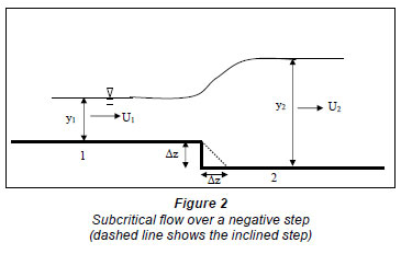
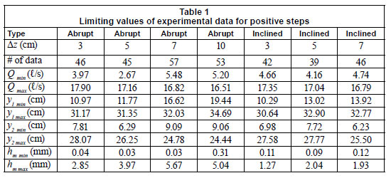
The present study addresses the flow over positive and negative steps in a subcritical open channel. Two types of step shape, an abrupt step and a 45º inclined step, were used in the experiments. For the positive steps, the abrupt step heights used were: 10 cm, 7 cm, 5 cm, and 3 cm; and for the inclined steps: 7 cm, 5 cm, and 3 cm. Similarly, for the negative steps, the abrupt step heights used were: 7 cm, 5 cm, and 3 cm; and for the inclined steps: 7 cm, 5 cm, and 3 cm. The experimental data has been analysed to obtain relations to represent the local losses as a function of the Froude number on the step and the relative step height defined for positive and negative steps.
Flow over a step
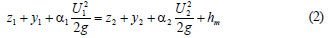
Sudden transitions will induce rapidly varied flow. Assuming that the frictional losses are negligible, the energy equation between Sections (1) and (2) (Figs.1 and 2) is:


where:
Hi is the total head at i-th section, i=1,2
hm is the local energy loss due to the step.
Eq. (1) may be written in open form as:
where:
z, y, and U represent the bed elevation, the water depth, and the average velocity, respectively
g is the acceleration due to gravity
a is the energy correction coefficient.
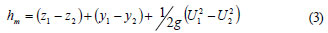
Formica (1955) showed that the values of a are very close to unity for sudden contractions (between 1.00-1.04), but slightly higher than unity for sudden expansions (up to 1.10). In the present study, the value of energy correction coefficient, a, is determined experimentally as a = 1.02 for positive steps (Orsel, 2002). Throughout the study, the energy correction coefficient is taken as unity. Solving Eq. (2) for the local loss, hm :
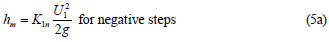
On the other hand, in the literature the local loss hm may be represented as a fraction of velocity head, U2/2g (Chow, 1959). In the present study, the following local loss equations were used:

The above equation can be non-dimensionalised by dividing each term with the flow depth as:
where:
Fr2 = is the Froude number at Section 2.
Similarly, Eq. (5a) can be non-dimensionalised as:
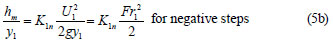
where:
Fr1 =  gy1 is the Froude number at Section 1.
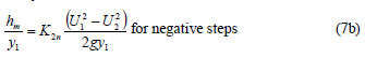
Another form of local loss is defined as (Chow, 1959):

Dividing each term by the flow depth, the non-dimensionalised form of Eq. (6a) is obtained as:

Similarly,
In the above equations subscripts p and n refers to positive and negative steps in coefficients K1 and K2, respectively.
Experimental study
The experiments were carried out in a horizontal rectang ular channel having 25 cm width, 50 cm depth, and 10.5 m length (Fig. 3). The channel is made of concrete and fibreglass. The section where the observations were done has fibreglass sidewalls and a concrete bottom. The steps used are made of fibreglass. The step heights used were 3 cm, 5 cm, 7 cm, and 10 cm for abrupt steps, and 3 cm, 5 cm, and 7 cm for 45º inclined steps. The water depths were measured by a movable point gauge, which has an accuracy of ±0.01 cm.
Water was supplied from a constant head tank having a maximum capacity of 125 ℓ/s through an 18 cm diameter pipe. The maximum capacity of the channel was 23.5 ℓ/s. Discharge entering the system was controlled by a valve in the delivery pipe. The depth of flow was adjusted by a sluice gate at the end of the channel. After the sluice gate, water is collected in a small basin, which directs the water to a return channel having a 30º triangular weir at the end. This triangular weir is used to measure the discharge with an accuracy of ±1.5%. The limiting values of experimental data for positive and negative steps are given in Tables 1 and 2, respectively. In the experiments conducted the range of the Froude number on the step was 0<Fr<0.5.

Analysis of data
Positive steps
The dimensional analysis applied to variables hm = f (U 2 ,y2 , Δz, g,φ) gives the following dimensionless parameters:

where:
Δz is the positive step height
φ is the inclination of the step
Fr2 is the downstream Froude number (Froude number on the step).
Positive abrupt steps
For the local energy loss hm, relationships which have the following forms have been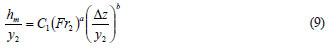 analysed:
where:
a, b, and C1 are the constants to be determined from the data. These constants are determined by using the best fit curves as: a=0.25, b=2.0, C1=0.70.
Therefore, the local loss for a positive abrupt step may be formulated as:
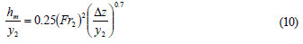
The plot of Eq. (10) is shown in Fig. 4 together with the standard deviation lines and data points. The best fit line has a correlation coefficient of R=0.85 and a standard deviation of 0.004.

Local loss coefficients for positive abrupt steps
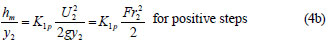
In order to calculate the numerical values of the local loss coefficients Eqs. (4b) and (6b) are used for positive steps. K1p defined in Eq. (4b) is calculated from the graph of hm/y2 versus Fr22 /2 (Fig. 5). The slope of the best fit line is nothing
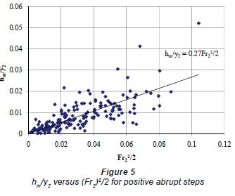
but the corresponding loss coefficient which is calculated to be 0.27. Similarly, K2p is determined from the graph of hm/y2 drawn vs.  as shown in Fig. 6. The slope of the best fit line is 0.53 which is the local loss coefficient defined by Eq. (6b) for positive steps.

Positive inclined steps
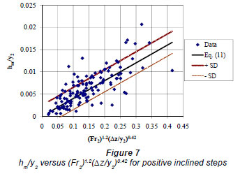
In the present study, the local loss for positive inclined steps is studied for only one value of φ=45º, to compare with that of abrupt steps. Therefore, the relationship does not include the inclination angle and an analysis similar to that for posi tive abrupt steps was performed. The equation obtained is as follows:
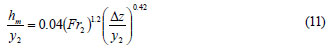
The plot of Eq. (11) and its standard deviation lines are shown in Fig. 7 together with data points. The correlation coefficient of the Eq. (11) is R=0.78 and the standard deviation is 0.0025.
Local loss coefficients for positive inclined steps
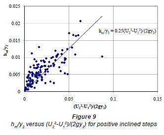
Local energy losses at 45º inclined steps can also be represented with local loss coefficients, K1p and K2p, which are defined in Eqs. (4b) and (6b), respectively. Figure 8 shows the variation of hm/y2 with respect to Fr22 /2. The corresponding slope of the best fit line is K1p which is equal to 0.15. Similarly, Figure 9 shows the change of h /ywith gy2 and the corresponding slope of the best fit line is the local loss coefficients, K2p, which takes a value of 0.25.

Discussion of results for positive steps 0.025
Formica (1955) obtained the values of K1 for sudden and 0.02 gradual contraction in width for rectangular channels. Based on hm/y2 = 0.15Fr22/2 Formica's results, Chow (1959) suggests to use an approximate 0.015 median value of K1=0.10 and K1=0.06 for abrupt and gradual contractions, respectively. In the present study, the values of the local loss coefficient expressed with Eq. (4) are: 0.27 and 0.15 for positive abrupt and inclined steps, respectively.
Morris and Wiggert (1972) suggested using a value of 0.4 for sharp transitions and 0.2 for wedge transitions in the case of contracting sections. Similarly, Brater and King (1976) obtained the local loss coefficient expressed by Eq. (6), K2=0.5 for abrupt contractions and suggested using a value of 0.1 for designing contracting channels. These values are compatible with the local loss coefficients obtained from the present experimental studies of 0.53 and 0.25 for positive abrupt and inclined steps, respectively.
Unfortunately, there is no published study which gives the local loss coefficients for contractions due to positive steps, and which could have been used for comparison purposes. It is believed that this study fills that gap and gives the average values of local loss coefficients, K1 and K2. The present study also provides a relation, which computes the local loss as a function of downstream Froude number, and relative step height, Δz/y2. Hence, it is suggested that Eqs. (10) and (11) are used for positive abrupt and 45º inclined steps, respectively.
Negative steps
The dimensional analysis applied to variables hm=f (Um ,ym,Δz, g,φ) gives the following dimensionless parameters:

where:
Δz is the negative step height,
φ is the inclination of the step and
Fr1 is the upstream Froude number (Froude number on the step).
Negative abrupt steps
For the local energy loss hm, relationships which have the following forms have been analysed:
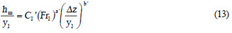
where:
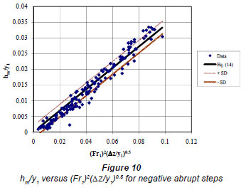
a', b', and C1', are the constants to be determined from the data. These constants are determined by using the best fit curves as: a'=2, b'=0.5, C1'=0.34. Therefore the local loss for an abrupt step may be formulated as:

The plot of Eq. (14) is shown in Fig. 10, together with data points and the standard deviation lines. The correlation coefficient of the Eq. (14) is R=0.98 and the standard deviation is 0.002.
Local loss coefficients for negative abrupt steps
Local loss coefficients are calculated for negative steps as was done for the positive step. The numerical values of the local loss coefficients are calculated by using Eqs. (5b) and (7b) for negative steps. K1n defined in Eq. (5b) is calculated from the graph of hm/y1 vs. Fr12 /2 (Fig. 11). The slope of best fit line is the corresponding loss coefficient which is calculated to be 0.40. Similarly, K2n is determined from the graph of hm/y1 vs.  gy1 as shown in Fig. 12. The slope of the best fit line is 0.89 which is the local loss coefficient defined by Eq. (7b) for negative steps.


Negative inclined steps
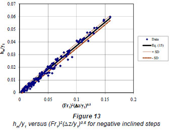
In this study, only an inclination of 45º was investigated for the negative step. Examination of the data revealed the following equation:

The plot of Eq. (15) together with the experimental data is shown in Fig. 13. The correlation coefficient of Eq.(15) is R=0.99 and the standard deviation is 0.002.
Local loss coefficients for negative inclined steps
Similar to the positive inclined steps, local losses at 45º
inclined steps can also be represented with local loss coefficients, K1n and K2n, which are defined in Eqs. (5b) and (7b), respectively. Figure (14) shows the variation of hm/y1 with respect to Fr12 /2. The slope of the best fit line is K1n, which is equal to 0.49. Similarly, Fig. (15) shows the change of hm/y1 with gy1 and the corresponding slope of the best fit line is the local loss coefficient, K2n, which takes a value of 0.97.


Discussion of results for negative steps
Comparing the results obtained for negative abrupt and negative inclined steps (φ=45º), it is seen, contrary to expectation, 0.05 that the local loss in negative abrupt steps is less than the local loss in negative inclined steps, by approximately 10%. The formation of the separation zone in abrupt steps might cause the flow to occur smoothly leading to less energy loss. Formica (1955) obtained the average values of the local loss coefficient for 8 different configurations of expanding channel widths. He defined the loss coefficient as a function of the square of the upstream and downstream velocity difference. For the abrupt expansion the average value of 0.82 is obtained. The minimum value of 0.27 is suggested for one of the configurations. It should be noted that the 45º expansion gives the highest loss coefficient of 0.87.
No study could be found in the literature for negative steps either. Comparison of the present data was made with the studies done for rectangular channels having expansion in width. Brater and King (1976) reported the local loss coefficient, K2=1.0 for abruptly expanding channels and suggested use of the 0.2 value for design purposes in expanding channels. Morris and Wiggert (1972) suggested using 0.75 for sharp tran sitions and 0.5 for wedge transitions in the case of expanding sections. In the present study, as explained above, the average values for the local loss coefficients for abrupt negative steps and 45º inclined negative steps were found to be 0.89 and 0.97, respectively.
This study thus fills the gap in the literature for negative steps. It is seen that local loss occurring due to negative steps depend on the Froude number and the relative step height. Hence, it is suggested that Eqs. (14) and (15) be used for negative abrupt and 45º inclined steps, respectively.
Relative energy loss for positive and negative steps
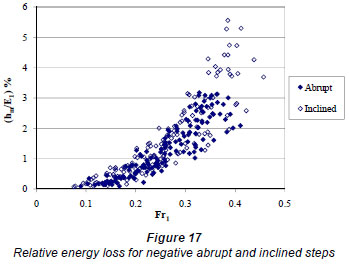
In the literature, it is commonly assumed that the magnitude of local energy loss will be small. To determine how small these losses are, relative local energy loss, hm/E was calculated for both positive and negative steps for the range of Froude numbers used in this study. E is the specific energy on the step for both cases, defined as the sum of depth and velocity head. For both of the step configurations, the Froude number and the specific energy on the step were used. Fig. 16 shows the relative energy loss (hm/E2)% vs. the Froude number (Fr2) on the step for positive abrupt and inclined steps. It can be seen from Fig. 16 that both losses are compatible, but that the abrupt loss is slightly higher than the inclined loss value. Similarly, Fig. 17 shows the relative energy loss (hm/E1)% versus the Froude number (Fr1) on the step for negative abrupt and inclined steps. This time, it is seen that, though the losses on the abrupt and inclined steps, are comparable, the abrupt step gives a loss that is slightly lower than that for the inclined step. It can be con cluded that the relative loss increases with increasing Froude number. Skogerboe et al. (1971) showed that the local loss coefficients are not constants. Also, in the present study it was found that the negative step yields more loss when compared to the positive step. This is also validated by the work of Brater and King (1976). The local loss coefficient, K2, was suggested to be 0.5 and 1, for abrupt contractions and expansions, respectively, even though Formica (1955) showed that in general sudden contractions have higher head losses than sudden expansions.

Conclusions
Based on the experiments performed and the obtained results for positive and negative steps in a subcritical open channel flow, for a Froude number range of 0<Fr<0.5, the following conclusions can be drawn:
• The local energy loss caused by positive and negative steps in a subcritical open channel flow is a function of the Froude number on the step and relative step height
• Local energy losses at abrupt positive steps may be computed by using Eq. (10):
• Local energy losses at 45º inclined positive steps may be computed by using Eq. (11):

• For all practical purposes, K1p can be taken as equal to 0.27 for positive abrupt steps and 0.15 for 45º inclined positive steps
• K2p can be taken as equal to 0.53 and 0.25 for positive abrupt steps and 45º inclined positive steps, respectively
• Abrupt positive steps generally introduce slightly higher local losses than the inclined positive steps; and the loss increases with increasing downstream Froude number
• Local energy losses at abrupt negative steps may be computed by using Eq. (14):

• Local energy losses at 45º inclined negative steps may be computed by using Eq. (15):

• For all practical purposes, K1n can be taken as equal to 0.40 for negative abrupt steps and 0.49 for 45º inclined positive steps
• K2p can be taken as equal to 0.89 and 0.97 for negative abrupt steps and 45º inclined negative steps, respectively
• Abrupt negative steps introduce slightly lower local losses than the inclined positive steps and the loss increases with increasing downstream Froude number
• The relative energy loss occurring in negative steps is higher than that occurring in positive steps
Acknowledgement
The authors would like to thank to İlker Örsel and Deniz Özdemir for performing experiments at Hydromechanics Laboratory of Civil Engineering Department, Middle East Technical University, Ankara.
References
BHALLAMUDI SM and CHAUDRY MH (1992) Computation of flows in open-channel transitions. J. Hydraul. Res. 10 77-93. [ Links ]
BINNIE AM (1975) laboratory experiments on the flow of water over a downward step in an open channel. Int. J. Mech. Sci. 17 583-587. [ Links ]
BRATER EF and KING HW (1976) Handbook of Hydraulics. McGraw-Hill, New York. [ Links ]
CHOW VT (1959) Open-Channel Hydraulics. McGraw-Hill, New York. [ Links ]
FORMICA G (1955) Esperienze preliminary sulle perdite di carico nei canali, dovute a cambiamenti di sezione (preliminary test on head losses in channels due to cross-sectional changes) L'Energia Elettrica 32 (7) 554-568. [ Links ]
MORRIS HM and WIGGERT JM (1972) Applied Hydraulics in Engineering. John Wiley & Sons, New York. [ Links ]
ÖRSEL SI (2002) Local Losses at a Step in a Sub-critical Open Channel Flow. M.Sc. Thesis, Department of Civil Engineering, Middle East Technical University, Turkey. [ Links ]
SKOGERBOE GV, AUSTIN LH and BENNETT RS (1971) Energy loss analysis for open channel expansions. J. Hydraul. Div. ASCE 97 (HY10) 1719-1736. [ Links ]
SWAMEE PK and BASAK BC (1991) Design of rectangular open channel expansion transitions. J. Irrig. Drain. Eng. 117 (6) 827-837. [ Links ]
SWAMEE PK and BASAK BC (1992) Design of trapezoidal expansion transitions. J. Irrig. Drain. Eng. ASCE 118 (1) 61-73. [ Links ]
SWAMEE PK and BASAK BC (1993) Comprehensive open-channel expansion transition design. J. Irrig. Drain. Eng. ASCE 119 (1) 1-16. [ Links ]
VITTAL N and CHIRANJEVII VV (1983) Open channel transitions: Rational method of design. J. Hydraul. Engin. ASCE 109 (1) 99-115. [ Links ]
Received 22 April 2010; accepted in revised form 8 March 2011.
* To whomall correspondence should be addressed. (90)-312-210 2477; fax: (90)-312-210 1262; e-mail: burcuas@metu.edu.tr
| a, a' | constants |
| b, b' | constants |
| C1C'1, | constants |
| E | specific energy |
| Fr | Froude number |
| g | gravitational acceleration |
| H | total head |
| hm | local energy loss due to step |
| K1p | local loss coefficient for positive steps defined in Eq. (4) |
| K1n | local loss coefficient for negative steps defined in Eq. (5) |
| K2p | local loss coefficient for positive steps defined in Eq. (6) |
| K2n | local loss coefficient for negative steps defined in Eq. (7) |
| U | average velocity |
| y | water depth |
| z | bed elevation |
| α | energy correction coefficient |
| φ | inclination of the step |
| Δz | step height |
Notation

