


Serviços Personalizados
Artigo
 Inglês (pdf)
 Artigo em XML
 Referências do artigo
Indicadores

Links relacionados
-
 Citado por Google
 -
 Similares em Google
Compartilhar

 Permalink
Water SA
versão On-line ISSN 1816-7950
versão impressa ISSN 0378-4738
Water SA vol.37 no.2 Pretoria Abr. 2011
The trigger-tube: a new apparatus and method for mixing solutes for injection tests in boreholes
Richard Ayuk Akoachere III,*; Gerrit Van TonderII
IDepartment of Geology and Environmental Sciences, University of Buea, BP 63 Southwest Region, Cameroon
IIInstitute for Groundwater Studies, University of the Free State, Bloemfontein, 9300, South Africa
ABSTRACT
the trigger-tube apparatus and method was developed for mixing solutes and tracers for injection tests. The apparatus is a cap-trigger tube segment and the technique mixes solutes in boreholes in 2 min. Trigger-tube with solute/tracer is introduced into the well, the trigger is released, the tube is withdrawn and the solute/tracer mixes with well water instantaneously to give a homogeneous mixture. Field tests using this method and apparatus for point dilution tests gave a Darcy velocity of 4.06 m/d, seepage velocity of 122.89 m/d and effective porosity of 0.33. Natural gradient tests gave a Darcy velocity of 4.06 m/d and natural velocity of 123 m/d, using tracer, for the same fracture at 21 m in borehole UO5, University of the Free State campus test site. The apparatus enables a comparatively shorter time for carrying out SWIW tests than is possible using the pump mixing method. Field tests gave results of 13 min for the trigger-tube method and 25 min for the pump mixing method, for a point dilution test using NaCl as a conservative tracer. The trigger-tube apparatus can be used for any borehole test that requires the introduction of a homogenous mixture.
Keywords: Field tracer test apparatus, Single-well test method, point dilution test apparatus, homogeneous solute mixer
Introduction
Borehole dilution is a well-established method for analysing groundwater velocity. It is a tracer technique that is performed in a section of a well that has been isolated by inflatable packers from the remainder of the well. A small amount of tracer is quickly injected into the isolated test section from a reservoir and is subjected to continual mixing in/out of the borehole by a submerged/surface pump as groundwater gradually replaces the tracer solution in the well. A log normalised concentrationversus-time curve is plotted and the magnitude of the horizontal velocity of the groundwater flow calculated. Testing vertically distinct sections of the well, a picture of the vertical groundwater velocity variation in the aquifer (near the well) can be obtained. The measurement of the lateral variability of the flow system depends on the number and distribution of monitoring wells. This method endeavours to account for the flow system distortions through a well screen. However, this accounting requires a calibration test for each well. The groundwater through-flow gradually removes the tracer introduced into the well from the well bore, to produce a time-concentration relationship from which the velocity is computed.
In a single-well injection-withdrawal-test (SWIWT), or the push-pull test, a tracer is introduced to the standing water column of the test well and allowed to drift, under a natural gradient, away from the well bore. After a period of time (a few hours to days depending on the velocity of the formation), the test well is pumped to retrieve the tracer plume. Groundwater flow velocity is then calculated, based on the amount of pumping needed to recover the tracer. The faster the groundwater flows, the farther the tracer plume migrates and the more pumping is needed to retrieve the plume. The drift or push phase of the test in such cases is shortened to prevent the tracer from moving too far away or escaping (Freeze and Cherry, 1979; Drost et al., 1968).
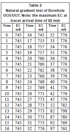
In natural gradient tests (multi-well tracer tests), a non reactive tracer is introduced into the standing water column in one well and the time it takes for the tracer to arrive at another well at a known distance is used to calculate the natural velocity (Devlin, 2002; Labaky et al., 2007).
Forced gradient tests (radial convergent tests) are carried out between 2 boreholes by using the one borehole as the point for the introduction of tracer (solute), as in point dilution tests, and the other borehole as an abstraction borehole. For the source borehole the point dilution test will give an estimate of the Darcy velocity q. Fitting the breakthrough curve measured in the abstraction borehole will yield the seepage velocity v from which the effective porosity could be estimated from the equation v= q/e (Lamontagne et al., 2002).
Natural gradient tests, point dilution tests, tracer tests, single well injection withdrawal tests (SWIWT) (push-pull tests) and forced gradient tests are all carried out based on a number of assumptions. The most important of these assumptions are:
• Solutes are injected as well mixed slugs
• The well mixing mechanism does not increase the rate at which the tracer moves out of the well
• The injection time is short compared to the overall length of time required to carry out the whole experiment (Neretnieks, 2007; Lamontagne et al., 2002)
However, every researcher who has ever carried out one of these tests in the field will attest that one of the major problems in the use of these tests in hydrogeological investigations is the field procedure which requires a homogeneous mix of solute to be created in the test well using a pump. The importance of the homogeneity of solute in the test well can never be overemphasised, and presents the greatest challenge to generating good data, irrespective of which type of tracer or test method is being applied. In fractured rock aquifers, where the tests are carried out with the fracture in a continuous flow field with the pump mixing method, it is exceedingly difficult to completely eliminate the influence of pumping on the rate at which the tracer moves into the fracture. This gives higher or lower velocities than would otherwise have been recorded.
At the test site used in this study, where groundwater velocities in the larger fractures are high (hundreds of meters per day), the overall time taken for tests is relatively short (tens of minutes), and, when using the method of pumping and mixing at the surface in a chamber (Lamontagne et al., 2002), the injection time is long compared to the overall time needed for the experiments. Thus it is difficult to get good data and accurate results.
Lamontagne et al. (2002), in their very instructive paper, came to one major conclusion: the potential for the wellmixing mechanism (by pump circulation) to increase the rate at which tracer mixes and moves out of the well is the main technical difficulty associated with point dilution test designs at present. They further concluded that future research on point dilution tests should quantify this problem and seek to develop instrumentation that would limit this potential bias. Neretneiks (2007) noted that the notion of Taylor dispersion is valid for the case when the traced solution is collected and mixed at the 'outlet' of the fracture. If there has not been time to even out the concentration between the streamlines, the 'dispersion' would not be seen if the fluid was rapidly pulled back, as in a SWIW test. Devlin (2002) affirmed that the chief disadvantage of the borehole dilution method by pump-mixing is the need for mixing in the well; that down-hole mixers have not proven reliable and that recirculation of the tracer solution from the well to the surface and back limits the depth at which the measurements can be made. The difficulties associated with calibration for an in-ground well screen are also non-trivial though necessary for calculations for groundwater velocity from pump-mixing point dilution tests.
Aim
After many failed tests and ambiguous results from field tests, due to the above assumptions not being met, we undertook to develop a new apparatus and method aimed at:
• Mixing the solute inside the borehole homogeneously on injection
• Instantaneously introducing solute inside the borehole (within seconds)
• Introducing the solute inside the borehole without perturbations.
Field test site
The Campus Test Site at the University of the Free State (UFS) is a test site for research covering an area of approximately 180 x 192 m. To date 30 percussion and 7 core-boreholes have been drilled. The site has been used a number of research projects, e.g. on Karoo aquifers (Botha et al., 1998) and on tracer tests in fractured aquifers (Van Wyk et al., 2001; Van Tonder et al. (2000).
Experimental
The trigger-tube apparatus
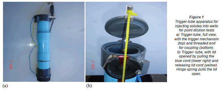
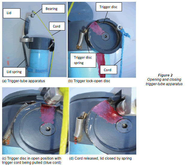
Tthe trigger-tube was designed and built after laboratory experimentation. It is made up of a 500 mm length of polyvinylchloride (PCV) piping with a lid and trigger mechanism at one end and a threaded coupling joint at the other. The trigger mechanism consists of a lid, a larger retractor spring, a trigger disc, a smaller retractor spring and a circular rubber seal (Fig. 1). A circular rubber seal is glued all round the lid to make the assembly leak-proof. The lid, which is hinged at one end of the tube, is opened by the larger retractor spring attached to it. At the opposite end to the hinge is the lock, which is L-shaped with a small bearing at the tip (Fig. 2). To close the lid, the cord (blue) attached to the trigger disc is pulled, to align the slit to the bearing (Fig. 2b), while the cord (yellow) attached to the lid is pulled simultaneously, bringing the lid's lock bearing into the trigger discs through the slit. Releasing the disc cord (blue) allows the small retractor spring to rotate the trigger disc anticlockwise, locking the lid in place. The lid cord (yellow) is then released. (To close: pull blue, yellow; release blue, yellow).
To open the lid, the cord (blue) attached to the trigger disc is pulled. The trigger disc is rotated clockwise by the small retractor spring which aligns the disc's slit to the lid's bearing; the large retractor spring then retracts, pulling the lid open (to open: pull blue) This trigger-tube has been tested to pressures equivalent to down-hole pressures of up to one hundred meters (100 m) in depth below the water table, and opened and closed smoothly. The trigger-tube is coupled with segments of PVC tubes of the same diameter to make up the trigger-tube assembly. Fourteen PVC tubes of 2 m lengths were used for the field tests to a depth of 28 m.
Solute (homogeneous mixing)
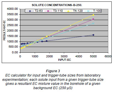
Determination of the test solute concentration is calculated by taking into consideration the concentration of the borehole water (background EC), the total volume of water in the borehole (the volume of water outside the trigger-tube and its concentration), the volume of the trigger-tube and the solute concentration in the trigger-tube, using the formulae below.
From laboratory experimentation, the concentrations for various trigger-tube sizes and EC values were calculated using the following:

ECT = solute EC required for carrying out test in the whole borehole (test EC)
rb = radius of borehole
rt = radius of trigger-tube
ECt = trigger-tube EC (pre-mixed solute EC in trigger-tube)
Vt = trigger-tube volume (includes volume due to thickness of tubes)
ECb = borehole background EC
VT = total borehole volume
Vb = borehole volume outside trigger-tube
h = length of test segment
Laboratory tests were carried out using trigger-tubes of 30 mm, 63 mm, 100 mm, 110 mm and 120 mm in diameter, to determine the input solute concentrations and required volumes of fluid for any desired initial solute concentration. The calculated values are given in Fig. 3.
EC meters
Two types of EC meter were used to measure water levels and profile the borehole, and to measure EC and temperature:
• Solinst Temperature/Level/Conductivity (TLC) meter
• A multi-parameter probe
Winch
A winch was used to lower and raise the trigger-tube assembly into the borehole. It was made up of a solid tripod, pulley, gear and sprocket and a stainless steel cable of 5 mm diameter.
Clamps
A set of 3 clamps is used to attach the trigger-tube assembly to the borehole casing and to couple and decouple the PVC tubes during insertion and withdrawal from the borehole. It is very important to clamp the trigger-tube assembly firmly to the borehole casing, in order to counter the enormous buoyancy forces that come into play; these push upward when the tube assembly becomes empty, once all the water has been pumped out of the trigger-tube assembly before the introduction of the solute. This may present a hazard if the trigger-tube assembly is not firmly attached.
Test procedure
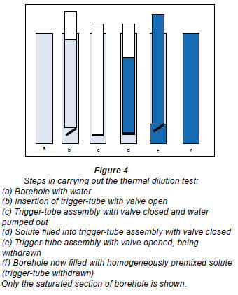
The procedure used to carry out the test (Fig. 4) using the trigger-tube assembly was as follows:
• The multi-parameter EC probe is placed downhole, below the water table at the required test depth for the investigation (21 m) (point dilution test). The probe is activated to start taking readings.
• The test well is profiled from top to bottom using a Solinst temperature/level/conductivity (TLC) probe, to get the background values of EC and temperature with depth, while the multi-parameter probe was placed at the fracture at a depth of 21 m.
• The trigger tube is inserted into the borehole down to the required depth by coupling 6 m length PVC pipes to the trigger tube, with its lid opened (Fig. 4a).
• At the required depth, the cords of the lid and the trigger disc are then pulled simultaneously to close the lid, with water inside the tube (Fig. 4b). The water in the tube and in the borehole is at the same level (static water level).
• The submersible pump is lowered to the bottom of the closed tube, and the water in the tube is pumped out (Fig. 4c).
• The submersible pump is withdrawn from the now empty trigger-tube assembly.
• With the lid of the tube closed, the water pumped from inside the trigger-tube assembly is poured into three 20 containers and is mixed with an appropriate mass of salt (in our case NaCl) to the required concentration for the triggertube (ECt). The well-mixed solute of predetermined concentration (point dilution test; natural gradient test) is poured into the tube up to the static water level (Fig. 4d).
• Using the EC calculator (Fig. 3), 500 µS ECT was found to be appropriate to give an ECT of 366 µS in the borehole. Three 20 ℓ plastic containers were enough to fill the trigger-tube assembly to the required test length of 16 m (depth of 12-28 m below water level). Fourteen PVC pipes of 63 mm diameter and 2 m length and 3.56 ℓ/m volume of solute and 56.96 ℓ of solute in three 20 ℓ plastic containers were used.
• The cord of the trigger disc is then pulled to open the lid and the trigger-tube assembly with the lid now opened is withdrawn at a constant rate of 1 m every 5 s, to avoid disturbing the water in the borehole (Fig. 4e).
• The borehole is immediately profiled by the pull-up and lowering method at 500 mm depth intervals, using the TLC probe, while the multi-parameter probe is placed at a depth of 21 m and measures the EC until the EC of the well returns to over 90% of its background EC value.
• At observation borehole UO7, another TLC probe is lowered simultaneously to the fracture at a depth of 21 m, and readings are taken at 1 min intervals (passive test). The combined readings from the 2 probes make up the natural gradient tracer test.
Results and discussion
Darcy velocity
The Darcy velocity q, for point dilution tests is given by:
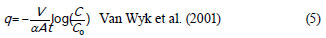
where:
V = volume of fluid contained in the test section
A = cross sectional area normal to the direction of flow
C0 = Tracer concentration at t = 0
C = tracer concentration at time = t
qa= ٧ where ٧ = apparent velocity inside well
a = borehole distortion factor (between 0.5 and 4; = 2 for an open well)
t = time when the concentration is equal to C
In practice either the radial flow solution or the parallel plate model is used to estimate the cross-sectional area A (Novakowski et al., 1998): For the radial flow model:

where:
rW = well radius,
b = the length of the tested section in the borehole.
For the parallel plate model:

where:
2b = equivalent aperture of the fracture rock.
Natural flow velocity
The natural flow velocity is given by:

where:
x = distance of observation well UO7 from test well UO5,
t = is the time taken for the tracer to travel from test well to observation well.

where:
q is the Darcy velocity which is equal to V when α =1 (parallel plate model for fracture has porosity as 1 at the fracture).
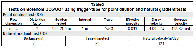
The results from tests using the trigger-tube for a point dilution test on borehole UO5 and a natural gradient test on borehole UO5/UO7 at the UFS campus test site showed that the solute was mixed to the desired EC within a minute of withdrawal of the tube assembly from the borehole (Table 1).
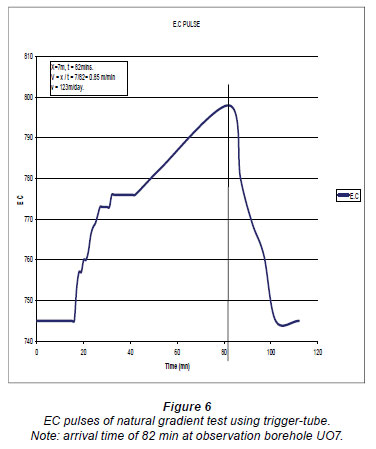
The data from the TLC probe in the passive natural gradient test were plotted on an x-y scatter diagram (Fig. 6); this shows the arrival of the peak pulse of EC 82 min after the release of the tracer (solute) in UO5. Using Eq. (8), a natural flow velocity of 123 m/d was determined.
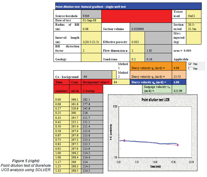
The data from the multi-parameter probe for the point dilution test in borehole UO5 was analysed using Eq. (5) in MS Excel SOLVER (Fig. 5), from which effective porosity, Darcy velocity and seepage velocities were calculated. This gave a Darcy velocity of 4.06 m/d, an effective porosity of 0.033 (3.3%) and a seepage velocity of 122.89 m/d (Table 2). From these results, the natural flow velocity calculated from the natural gradient test (123 m/d)and the seepage velocity of calculated from the point dilution test (122.89 m/d) were found to be equal, which shows that the trigger-tube test results are accurate. In comparison, results obtained for the same fracture at 21 m, from tests carried out by Van Tonder et al. (2000) using the pump-mixing mechanism (Table 3), give the same value (0.03) for the effective porosity but different values for seepage velocity and Darcy velocity using radial convergence tests and injection withdrawal tests.
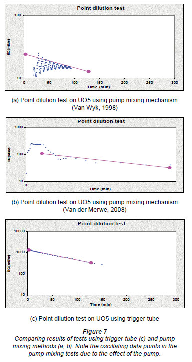
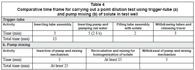
Comparing the results from tests carried out on the UFS campus test site using the trigger-tube to those gathered over a number of years by other researchers using the pumpmixing mechanism (Table 4) it is evident that the total time for set-up and introduction of tracer is shorter when using the trigger-tube than when using the other methods. When using the trigger-tube the smoothness of the plotted data is better. The calculated seepage velocity and natural velocity are equal when using the trigger-tube but not when using other methods (Figs. 6 and 7).
Conclusion
• From the results of the field tests it was concluded that the trigger-tube apparatus and test method for the mixing of solutes for injection tests in wells was successful in satisfying the 3 most important assumptions on which the point dilution test, single well injection withdrawal test, natural gradient test and forced gradient test are based, namely: Solutes are injected as well mixed slugs
• Introduction of solute by the trigger-tube does not increase the rate at which the tracer moves out of the well
• The injection time is short compared to the overall length of time required to carry out the whole experiment
Thus, a very useful apparatus and method for carrying out field tests that involve the injection of homogeneously mixed tracers/solutes in tests wells has been developed, which is userfriendly, cost-effective and accurate. Use of the trigger-tuber apparatus has the following advantages over use of the pumpmixing mechanism:
• No perturbation of well since there is no pumping in the well
•A specialised pump (peristaltic, etc.) is not required
•Isolation of test section or use of packers is not necessary
•No recirculation of borehole water which can affect the rate of tracer entry into the test well
• Better control of solute concentration (predetermined)
• No mechanism for mixing of solute downhole since the solute is more homogenously pre-mixed
• The whole length of the borehole can be tested at once
• This test method uses few instruments and as such is quicker to set up and carry out
• The solute is released at once (instantaneously)
• Simple equipment to transport and handle
• Economical, as the trigger-tube is inexpensive to construct
• Accurate data acquisition
Disadvantages of the trigger-tube apparatus are as follows: The pipes for the trigger-tube assembly are bulky to carry for very deep boreholes. Also, there is a hazard during the transition between emptying the trigger-tube and filling it with a tracer if the tube assembly is not securely attached; the empty tube becomes buoyant with a tremendous lifting force.
Acknowledgements
We thank the Water Research Commission (WRC) of South Africa for funding this research under the 'Bulk Flow Project' at the Institute for Groundwater Studies, University of the Free State, Bloemfontein. The valuable assistance of Mr Pete Botes of the Instrumentation Department of the University of the Free State is also acknowledged.
References
BOTHA JF, VERWEY JP, VAN DER VOORT I, VIVIER JJP, COLLISTON WP and LOOCK JC (1998) Karoo Aquifers; Their Geology, Geometry and Physical Behaviour. WRC Report No. 487/1/98. Water Research Commission, Pretoria, South Africa. [ Links ]
DEVLIN JF (2002) Groundwater Velocity Probe. US Patent 6393925. [ Links ]
DROST W, KLOTZ D, KOCH A, MOSER H, NEUMAIER F and RAUERT W (1968) Point dilution methods for investigating ground water flow by means of radio isotopes. Water Resour. Res. 4 125-146. [ Links ]
FREEZE RA and CHERRY JA (1979) Groundwater. Prentice-Hall Englewood Cliff Inc. NJ. 604 pp. [ Links ]
LABAKY W, DEVLIN JF and GILHAM RW (2007) Probe for measuring groundwater velocity at the centimeter scale. Environ. Sci. Technol. 41 (24) 8453-8458. [ Links ]
LAMONTAGNE S, DIGHTON J and ULLMAN W (2002) Estimation of groundwater velocity in riparian zones using point dilution tests. CSIRO Land and Water Technical Report 14/02, Adelaide. CSIRO. [ Links ]
NERETNIEKS I (2007) Single well injection withdrawal tests (SWIW) in fractured rock. Some aspects on interpretation. SKB Rapport R-07-54. Svensk Kärnbränslehantering (Swedish Nuclear Waste Co.) AB, Stockholm. [ Links ]
NOVAKOWSKI KS, LAPCEVIC PA, VORALEK J and SUDICKY EA (1998) A note on a method for measuring the transport properties of a formation using a single well. Water Resour. Res. 34 (5) 1351-1356. [ Links ]
VAN DER MERWE CJ (2008) Hydraulic Assessment of Low-yield Boreholes in Fractured Rock Aquifers. M.Sc. Thesis, University of the Free State. [ Links ]
VAN TONDER GJ, BOTHA JF, CHIANG W-H, KUNSTMANN H and XU Y (2001) Estimation of the sustainable yields of boreholes in fractured rock formations. J. Hydrol. 241 70-90. [ Links ]
VAN WYK B, DE LANGE F, XU Y, VAN TONDER GJ and CHIANG W-H (2001) Utilization of Tracer Experiments for the Development of Rural Water Supply Management Strategies for Secondary Aquifers. WRC Report No. 733/1/01. Water Research Commission, Pretoria, South Africa. [ Links ]
VAN WYK AE (1998) Tracer Experiments in Fractured Rock Aquifers. M.Sc. Thesis, University of the Free State (unpublished). [ Links ]
Received 17 July 2009; accepted in revised form 1 February 2011.
* To whomall correspondence should be addressed. (237) 97861637; fax: (237) 332 22 72; e-mail: rakoachere_ayuk@yahoo.com

