


Serviços Personalizados
Artigo
 Inglês (pdf)
 Artigo em XML
 Referências do artigo
Indicadores

Links relacionados
-
 Citado por Google
 -
 Similares em Google
Compartilhar

 Permalink
Water SA
versão On-line ISSN 1816-7950
versão impressa ISSN 0378-4738
Water SA vol.35 no.1 Pretoria Jan. 2009
Flow-gauging structures in South African rivers part 1: an overview
P WesselsI, *; A RooseboomII
IDepartment of Water Affairs and Forestry, Private Bag X313, Pretoria 0001, South Africa
IIUniversity of Stellenbosch, Dept of Civil Engineering, Private Bag X1, Matieland 7602, South Africa
ABSTRACT
Accurate hydrological information is of paramount importance in a dry country such as South Africa. Flow measurements in rivers are complicated by the high variability of flows as well as by sediment and debris loads. It has been found necessary to modify and even substitute certain internationally accepted gauging structure designs to overcome local practical problems and improve accuracies.
This, Part 1 of a paper in 2 parts, concentrates on the attributes of different types of gauging structures and the information provided on the different structures will assist the reader with the selection of an appropriate structure. The historical development of the gauging structure network in South African rivers is briefly discussed. Gauging structures used in South African rivers and basic design criteria for the preferred structures at this stage, based on past experience, are discussed:
• Crump weirs
• Sharp-crested weirs
• Sluicing flumes.
This paper reflects the lessons that have been learnt by DWAF and other South African organisations and should be of value to others who have to perform flow measurements under similar climatic conditions. Factors that may adversely impact on gauging accuracy are also pointed out in the conclusion. Part 2 of the paper contains information on the calibration theory and techniques to rate the preferred gauging structures.
Keywords: gauging structures, Crump weirs, sharp-crested weirs, modular flows, Parshall flume, Hydro flume, sluicing flume, flow measurement, rivers
Introduction
Accurate hydrological information is of paramount importance, particularly in a dry country such as the Republic of South Africa. Flow measurements in South African rivers are often not only complicated by the high variability of water discharges, but also by heavy sediment and debris loads. In order to cope with these problems, it has been found necessary to modify and even substitute certain standard gauging station designs.
The gathering of hydrological data in South Africa is the responsibility of the Directorate of Hydrological Services in the Department of Water Affairs and Forestry (DWAF).
A flow-gauging station may be defined as follows:
'A gauging station is a site on a river which has been selected, equipped and operated to provide the basic data from which systematic records of water level (stage) and discharge may be derived. Essentially it consists of a natural or artificial river cross-section where a continuous record of stage can be obtained and where a relation between stage and discharge can be determined.' (Lambie, 1978).
From this definition it is obvious that two actions are required to measure discharge; the gauging of stage and the translation of stage into discharge. Various methods are used by DWAF to convert stage records into discharge or flow-rating records. Direct measurement techniques include the use of flow-gauging weirs and velocity-area methods, whilst indirect measurements are used mainly to derive peak discharges from peak observed flood levels after flood events. By combining the two methods, a discharge rating curve with a wide range can be produced at a point of interest.
The development of flow gauging in South Africa Historical overview
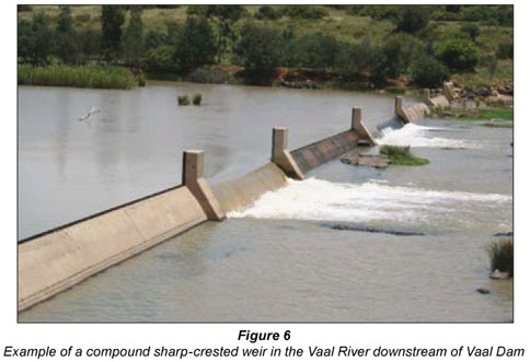
The present network of flow-gauging stations in South Africa has grown from isolated observations of water levels (stage) on an ad hoc basis to an extensive network of stations across the country. Standardised gauging stations to suit local conditions have been developed which include purposely-designed gauging structures, such as compound weirs with overflow crests at different levels.
The first long-term daily stage measurements in the country were started in 1865 by the Port Elizabeth Town Council on the Van Stadens River. During July 1885 the Kimberley Water Works Company started with daily stage measurements at their pumping station on the Vaal River at Riverton (Hurley, 1905). According to available records in DWAF, the only other gauging station operational earlier than 1900 was established in 1898 on the Breede River near Robertson (Muller, 1977).
The first gauging structures constructed specifically to measure flow in South African rivers were completed in 1904 in the then Transvaal Province (Menné, 1960). New structures were constructed until 1916 when a lack of funds, due to the First World War, brought a temporary halt to the expansion of the gauging network. At the time there were at least 17 compound gauging weirs in the Transvaal, where stages were gauged continuously using mechanical recorders. At least 8 compound gauging weirs had been established in the Cape Province and 3 gauging weirs in the then Orange Free State Province (Kanthack, 1924). The Rand Water Board (a board supplying water mainly to the Gauteng-area) established several gauging stations during 1915.
The variations in the numbers of gauging stations in South African rivers since 1900 are shown in Fig. 1. The influence of both world wars on the growth of the network is clear from this figure. After World War II the number of operational gauging stations grew rapidly until the early 1970s. Due to approaching a near optimal number of gauging stations across the country, the start of a network planning programme as well as financial constraints, the number of operational gauging stations remained between 780 and 880 since the beginning of 1975. In the early 1990s nearly 90 stations, mainly structures not complying with departmental gauging standards, were closed as part of the network optimisation process.
Discharge is gauged by means of purposely-designed compound gauging structures at nearly all these stations. Discharge was gauged at 782 different geographical positions in South African rivers by the end of 2007. Of these stations, approximately 55% include components with sharp-crested weirs and 35% with Crump-weir crests. The remainder of the stations are structures, such as dams, broad-crested weirs and also velocity-area gauging sites. Flow records at these stations are compiled from roughly 3 400 continuous recordings of stage, gate openings, meter readings and rainfall and evaporation readings at dams.
Unlike the practice in a number of other countries, sections rated by velocity-area methods have not been used extensively in South Africa in the past for the following practical reasons:
- Large distances to the respective sites and generally short runoff periods make it logistically difficult to fully rate sections within available time limits
- Rainfall events generating high runoff normally occur over large areas, resulting in a number of velocity-area sites that need to be rated simultaneously
- High rainfall intensities, making access to sites hazardous
- A lack of skilled manpower to undertake the required velocity-area gauging measurements,
- The tedious process of performing velocity-area measurements with mechanical current meters
- Unstable or changing stream-channel conditions (variation in roughness and cross-section parameters) during flood events.
It has thus been the policy in the South African Directorate of Hydrological Services to build measuring structures. The biggest advantage of a permanent structure is that it can be pre-calibrated. With the construction of a gauging structure a section of a stream channel is stabilised and an artificial control is created with a relatively stable and known theoretical relationship between stage and discharge.
Gauging structure installations General design criteria
A complete flow-measuring installation consists of 3 main components (BSI 3680, 1986; ISO 1438/1, 1980):
- An approach channel
- A downstream channel
- The gauging structure
The condition of each of these components affects the overall accuracy of the measurements.
Design parameters include features such as weir finish, channel roughness, cross-sectional shape of the channel, channel slope and the influence of control devices upstream or downstream of a gauging structure. Velocity variation in magnitude and direction in the approach channel can have an important influence on the performance of a structure. After the construction of a gauging structure, any change in condition that could influence the discharge characteristics must be prevented.
Approach channel
Flow in the approach channel shall be smooth, free of disturbances and shall have a velocity distribution as constant as possible over the cross-sectional area. This can only be attained with a long straight approach channel free of projections on the sides or the bed.
In artificial channels with uniform cross-section, an approach channel with a minimum straight length of at least 5 times the channel width is required. In natural streams, a reasonably uniform approach channel with an even longer straight length is sometimes required to ensure a relatively regular velocity distribution. If flow enters the approach channel through a bend, or if flow is discharged into the channel through a conduit with a smaller cross-section,, or at an angle, a longer straight length of channel will be required upstream of a structure.
The slope of the approach channel should not be too steep. As long as the Froude number (Fr) in the natural channel before the construction of a gauging structure is less than 0.5 for the highest discharge to be gauged accurately, the slope of the channel is still acceptable (Ackers et al.,1978; WMO, 1980). Depending on the type of gauging structure to be used, the Froude number in the channel at the point of stage measurement must be less than 0.4 for the design discharge, with the gauging structure in place (Van Heerden et al., 1986).
In a natural stream, the Froude number is determined as follows:

where:
Q = discharge (m3/s)
B = top width of stream (m)
A = cross-sectional area (m2)
g = gravitational acceleration (9.81 m/s2)
Downstream channel
Conditions in the channel downstream of the structure determine tail-water levels. An accurate survey of the downstream channel is therefore required by the designer to determine a stage-discharge relationship for the unobstructed channel at the site of the proposed structure. This is done by means of a backwater calculation. The results of these calculations are used for the hydraulic design of the measuring structure. This includes the determination of the type of structure to be used; the maximum and minimum discharge to be gauged accurately, the minimum crest level and shape of the proposed structure.
If a measuring structure has been designed to operate under modular or non-drowned flow conditions, the impact of tail-water levels, due to the channel conditions downstream of the structure, on gauging accuracy is of little importance. However, a downstream gauge should be provided to measure tail-water levels to determine when submerged flow occurs. It is impractical to make all structures high enough to avoid submergence at very high discharges. Structures designed to operate under both modular and submerged flow conditions require additional instrumentation to monitor tail-water levels continuously.
If scour is likely to occur downstream of a structure, protective measures need to be put in place.
Gauging structure
A gauging structure must be solid, watertight and capable of withstanding flood-flow conditions. It should be constructed on a stable foundation and the crest of the structure should be placed perpendicular to the direction of flow in the stream. The profile of the crest of the structure should be designed in such a way that a small change in discharge will cause a measurable change in stage. The structure should act as a control over a wide range of discharges without excessively raising the water level upstream of the structure.
During the construction of a structure, care should be taken that the surfaces over which water flows are smooth, especially near the weir crest. The structures should also be built to close tolerances. Flank walls should be parallel and vertical and should extend upstream past the stage- measuring position.
The main types of measuring or gauging structures that have been used in South Africa to date are:
- Thin-plate or sharp-crested weirs:
- V-notch crest (usually 90º angle)
- Rectangular crest (full width or contracted)
- Long-base weirs:
- Broad-crested weirs (round-nosed or rectangular profile)
- Triangular profile weirs (horizontal Crump or V-Crump)
- Nappe-profile spillways (Ogee)
- Flumes:
- Parshall flume
- Hydro flume
- Sluicing flume.
Gauging structures in South Africa Weir-type structures
Flows in South African rivers vary considerably with time and therefore it has been policy in the Directorate Hydrological Services to build measuring structures. The biggest advantage of a permanent structure is that it can be pre-calibrated. The idea behind a measuring or gauging structure is to create an artificial control in the river with a known relationship between stage and discharge.
Two types of weirs are mainly used to gauge discharge in South African rivers, namely sharp-crested and long-base weirs. The difference between long-base weirs and sharp-crested weirs is the average dimension of the structure in the direction of flow. It is also possible to distinguish between different types of long-base weirs; namely broad-crested, triangular profile weirs and nappe-profile or ogee spillways. Of the various long-base weirs, only the Crump-type triangular profile weirs have been used widely to gauge discharge in South African streams. The rectangular or horizontal sharp-crested weir and the various Crump-weir structure layouts will be discussed briefly.
Rectangular sharp-crested weirs (thin-plate weirs)
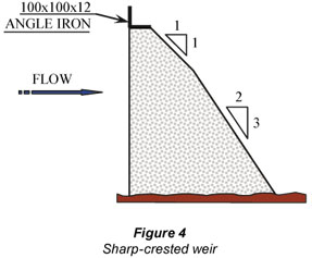
A thin-plate weir has a crest profile consisting of a narrow horizontal top surface at a right angle to the upstream face of a steel plate and a chamfer of not less than 45° on the downstream edge. Thin-plate weirs are widely used to gauge flows in hydraulic laboratories. Extensive hydraulic model tests have been performed on rectangular thin-plate weirs to establish formulae to rate this type of structure under a wide variety of flow conditions (Ackers et al., 1978).
The crests of thin-plate weirs are rather fragile and easily damaged by debris in natural streams. Due to this, true thin-plate weirs are only used on a very limited scale in natural streams. The shape of the thin-plate weir was modified in South Africa with the addition of an angle iron to form the crest of a sharp-crested weir. This structure is much more robust than the classical thin-plate weir and is more suitable for use in natural streams and rivers. The calibration formula to rate thin-plate weirs was also adjusted by the Department of Water Affairs and Forestry to allow for the use of angle-iron crests (Kriel, 1963).
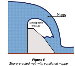
Modular flow conditions exist when the discharge over a weir is not influenced by the downstream water level. In order to gauge discharge accurately it is also important to ensure that the pressure on the lower surface of the nappe over the weir crest is full atmospheric (see ventilation of the nappe later in paper). The greatest disadvantage of the sharp-crested weir is its sensitivity to non-modular or drowned flow conditions. When the water level downstream of a weir rises above the crest level, it starts to increase the gauged head upstream of the weir. If no corrections are applied to adjust for the effect of submergence, the accuracy of flows gauged with sharp-crested weirs will be adversely affected.
Design criteria for sharp-crested weirs
Upstream head-measurement section
The water surface upstream of a gauging weir is not horizontal and the location of head measurement (stage above lowest crest level) depends on the surface profile of the water flowing over the structure. The water surface immediately upstream of a structure has the form of a draw-down curve. If the head-measuring section is placed too far upstream of the structure, energy losses may influence stage measurement. The upstream head-measuring section should therefore be placed at such a position that these influences are minimised. Both these effects will be predominant at high heads rather than at low heads. The location of the measuring section upstream of a structure is usually defined in terms of the maximum total design head (Hd) of a structure.
The recommended position of the head-measuring section for thin-plate and sharp-crested weirs is 4 times the total design energy head (Hd) upstream of the crest of the structure. Any variation in water levels should be monitored by means of gauge plates and stage recording instruments at this section.
Downstream head-measurement section
Drowned or non-modular flow conditions occur as soon as water levels downstream of the weir start to influence the discharge over the structure. Levels should be measured at a section far enough downstream of the structure to minimise the influence of turbulent conditions on the head measurements. The section should not be placed too far downstream of the structure as the channel slope and roughness may influence stage measurement. If there are any local obstructions that may influence the water levels over the total width of the channel, the head-measuring section should be placed upstream of these obstructions.
Practical experience showed that for a structure with a mean crest height (Z) above the streambed and a total design energy head (Hd) in a fairly uniform channel, the head-measurement section should be placed roughly at a distance 10 times (Z + Hd) downstream of the structure.
Upstream pool requirements
Although theory has been developed and calibrated to rate sharp-crested weirs with shallow upstream pools a certain minimum pool depth (P) is required to ensure accurate gauging. In order to keep the approach velocities within acceptable limits the minimum pool depth for a sharp-crested weir in a natural stream should comply with the following criteria:
- P >
 with Hd as the total design energy head or
 - P > 0.5m
In addition to this requirement, practical experience showed that the Froude number (Fr) at the upstream head measurement section should be less than 0.4 (Fr < 0.4). The pool should also extend upstream of the structure for a minimum length exceeding 5 times the top water surface width at the weir section for the design discharge.
Ventilation of the nappe
The equations used to determine discharge over sharp-crested weirs for modular flow conditions require proper ventilation to guarantee atmospheric pressure underneath the nappe. If the nappe is not properly ventilated the discharge over the structure will be underestimated. The provision of side contractions usually ensures adequate access to air from the sides to the underside of a nappe. Full-width rectangular weirs require the provision of ventilating ducts to aerate the nappe (Ackers et al., 1978).
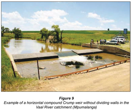
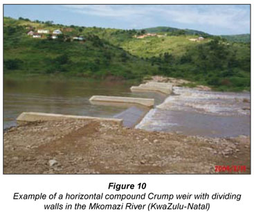
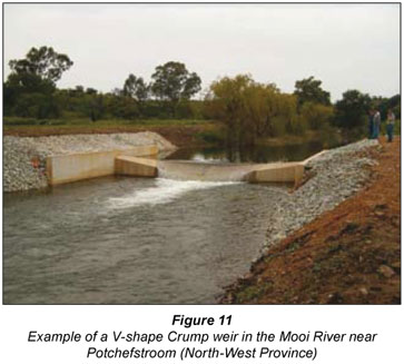
Triangular profile weirs
The Crump weir is at present the most popular type of triangular weir worldwide. E.S. Crump published a paper during 1952 in England in which he described a new type of triangular profile weir (Ackers et al., 1978; BSI 3680, 1986). The upstream and downstream slopes of this triangular profile weir are 1:2 and 1:5 respectively. There are two types of Crump weirs used for flow measurement in natural streams, namely the horizontal or rectangular Crump weir and the V-shape Crump weir. In South Africa, the side slopes of the V-Crump are standardised at 1 vertical to 10 horizontal. V-Crump weirs are usually only used in smaller streams and artificial canals with relatively low sediment loads. V-Crump weirs are also utilised in streams where low discharges are expected to contribute a large percentage of the total annual runoff volume to be gauged.
The Crump weir is relatively easy to construct. It is a robust structure and is insensitive to minor damage to the triangular profile of the crest. The greatest advantages of a Crump weir are a stable and constant coefficient of discharge in the modular flow range and the relative insensitivity of the structure to drowned flow conditions.
Design criteria for Crump weirs
Upstream head-measurement section
The recommended position of the head-measuring section for both horizontal and V-Crump weirs is 2 times the total design energy head (Hd) upstream of the crest of the structure. Variation in water levels should be monitored by means of gauge plates and stage-recording instruments at this section. Flank walls should be vertical, straight and parallel and should extend upstream past the head-measuring position for a length equal to 2 times the total design energy head (Hd).
Downstream head-measurement section
The position of the downstream head-measurement section is determined in exactly the same way as described for the sharp-crested weir.
Upstream pool requirements
The minimum required pool depth for horizontal and V-Crump weirs in natural streams is:
P > with Hd as the total design energy head
In addition to this requirement, practical experience showed that the Froude number (Fr) at the upstream head measurement section should be less than 0.4 (Fr < 0.4). The pool should also extend upstream of the structure for a minimum length exceeding 5 times the top water surface width at the weir section for the design discharge.
Truncation of a Crump weir
The Crump weir may be truncated as shown in the sketch to save on concrete. If the structure is truncated as shown there is no detectable change in its performance under either modular or drowned flow conditions.
Flume structures
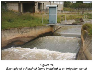
In South Africa flume structures, such as Parshall flumes, are mainly utilised in irrigation canals. This may be attributed to the relatively small increase in water levels (small energy loss) caused by flume- type structures in canals. Generally, the floor of a flume is close to the same level as the bottom of the canal assisting in the limited increase in water levels upstream of a flume.
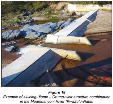
In natural streams sediment build-up is experienced upstream of gauging-weir structures. If sediment levels are too high, the effective and accurate operation of gauging weir structures is threatened. In an attempt to limit sediment build-up upstream of structures, DWAF developed the Hydro flume and sluicing flume to be used in combination with gauging weir structures.
The three flume types will be discussed briefly.
Parshall flume
R.L. Parshall developed a flume during the 1920s in the United States of America to provide a gauging structure that would overcome some of the problems experienced with weirs. The flume consists of a converging inlet section with a horizontal floor, a short throat section with a floor that slopes downwards, and a diverging outlet section with a floor that inclines upwards; each of these sections has vertical side-walls.
The complex geometry of the Parshall flume causes problems during construction, probably the biggest disadvantage of the flume. A Parshall flume is also a relatively expensive structure, mainly due to its complex geometry. The fact that water levels should be monitored at a specific location in a Parshall flume creates problems if a flume is used in combination with other structures.
The Parshall flume is particularly suitable for use in irrigation canals. This is mainly because of the relatively low energy head loss through the flume. Due to the high velocity of water passing through the throat, sediment is transported easily through the flume. The throat width (b) of a Parshall flume dictates the size of a flume. It is possible to distinguish between two groups of flumes, namely the standard range of Parshall flumes and large Parshall flumes. The modular limit of the standard range of flumes is 60% and that of the large flumes 80% (ISO 9826, 1990). Modular flow conditions exist if the submergence ratio, expressed as  with h2 the downstream head and h the upstream head, is less than the modular limit of a particular flume.
The throat width of standard flumes varies between 0.305 m and 2.44 m. Flumes with throat widths between 3.05 m and 15.24 m are classified as large flumes. Although the basic shape of the two flume groups is the same, the dimensions and formulae to rate the two groups are different. Dimensions of the flumes in the two groups are well documented and can be obtained in Ackers et al., 1978 or WMO, 1980.
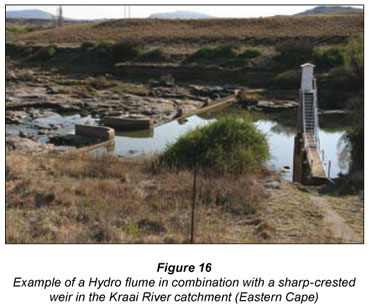
Hydro flume
One of the most serious problems to overcome when gauging with weir structures is the heavy suspended sediment load found in most of South African streams. The construction of a weir reduces the flow velocity and consequently lowers the sediment transport capacity of the stream. Sediment deposition occurs in the pools upstream of weirs and this could have serious negative impacts on gauging accuracy at these structures. In some cases, the deposit of sediment, a few meters upstream of the structure, becomes higher than the level of the lowest weir crest. Such high sediment levels cause the weir to lose its function as an artificial control and it can therefore not be rated theoretically.
Sediment deposition at gauging weirs does not only influence the rating of the stations but also blocks stage-measuring equipment and hampers its effective functioning. This may cause a partial or total loss of stage and flow records at a station. A structure, the Hydro flume, was developed by DWAF during 1966 to try and limit the build-up of sediment in the upstream pools of gauging weirs.
These flumes were only used in combination with sharp-crested and broad-crested weirs. The Hydro flume consists of an inlet section with a floor that inclines upward with a 1:10 slope and a throat section with a horizontal floor. The wing walls in the inlet section are vertical and parabolic in shape. These walls were shaped by means of hydraulic model studies in an attempt to minimise the formation of standing waves in the flume. The floors of these flumes were constructed as low as possible above the normal riverbed and the flumes were utilised as the lowest crest in a compound weir. This was done to allow the transportation of sediment through the flume and thus limiting the retention of sediment in the pools upstream of weirs.
Although Hydro flumes lowered sediment levels in the proximity of the flumes, sediment levels in front of adjacent sharp-crested weir sections were still unacceptably high (Muller, 1977). The use of these Hydro flumes did not prevent the blocking or covering of the inlet systems by sediments. This was due to the stage measurement system being located in the pool upstream of the structure at a level lower than the floor of the flume. The Hydro flume has only been partially successful and is therefore not widely applied.
Sluicing flume
DWAF has dealt with the negative impacts of sedimentation on gauging by dredging the pools upstream of gauging-weir structures when required and by flushing inlet systems when blocked. This is very time-consuming and expensive and it often happens that a pool fills up again with sediment during the first flood runoff after such a cleaning operation.
The need for the development a gauging structure that can overcome the sediment problem in upstream pools of gauging weirs has been quite apparent. At the request of DWAF, the Water Research Commission (WRC) made funds available for a research project to develop a new gauging structure for use in sediment-laden streams in South Africa. The aim of the project launched during 1992 at the University of Stellenbosch was the development of a flume-type structure with the following characteristics:
- Operate as the lowest crest in a compound weir
- Work in combination with existing weir types where sedimentation problems exist
- Allow the free passage of sediment
- Lower the deposition level of sediment in upstream pools
- Accommodate the monitoring of stage levels inside the flume in an area free of sediment
- Provide accurate gauging of flow over a wide range of discharges.
Over a 6 year period various models of flume structures were tested in the hydraulic laboratory of the University of Stellenbosch. This resulted in the development of the sluicing flume (Rossouw, et al., 1998) with 3 standard depth-to-throat width ratios (d/b = 1; 0.5 and 0.25). A sluicing flume, with a d/b ratio of 0.5, is shown in Fig. 17. This structure has the following advantages:
- The flume structures can be used in combination with adjoining sharp-crested or Crump weirs
- A trapezoidal shaped throat at the downstream end of the flume forms the control section and permits the accurate rating of discharge in the flume
- Stage is recorded inside the flume between the parallel sidewalls just upstream of a transition zone between the rectangular and trapezoidal sections of the flume and is used to determine the discharge through the flume and over the adjoining weir structures
- It has been successfully applied in rivers with heavy sand loads
- The upstream ends of the flume walls are sloped at 45º angles to reduce the risk of the walls collecting floating debris
- A horizontal flume floor allows the free passage of sediment
- The risk of sedimentation in the flume is reduced to a great extent due to the smooth transition between the rectangular and trapezoidal sections that continuously accelerates the flow inside the flume.
Hydraulic model tests on the final flume layouts showed that although it is not possible to prevent the deposition of sediment inside the flume under low-flow conditions completely, the total impact is limited. Sediment is deposited in the flume during the falling phase of a flood, especially when the sediment level upstream of the flume is higher than the flume floor. The flume will be cleared of sediment during the rising phase of a following flood. The control section of the flume remains free of sediment deposits and where deposits occur inside the flume, the sediment layer is relatively thin and therefore does not seriously affect the calibration accuracy of the flume.
Conclusion and recommendations
The gauging structures which have been discussed can generally be calibrated under ideal laboratory conditions to deliver discharge values that are accurate within 5%. Problems in practice, however, often lead to lower overall accuracies. Common practical problems experienced, are:
- Incorrect stage measurements or settings of instruments (human errors)
- Downstream submergence (drowned flows)
- Sediment build-up
- Accumulation of debris on weir crests.
Human errors, especially errors involving stage measurements, have a huge detrimental impact on gauging accuracy achievable in practice. Stage errors could result in serious gauging errors, especially under low discharge conditions or in a case of a gauging structure that is not properly designed or not constructed to close tolerances.
Drowning can be limited by using structures that are less susceptible to drowning, e.g. Crump weirs and sluicing flumes. Drowning can also be dealt with by measuring the downstream water level and applying proper correction factors. If no corrections are applied, errors in excess of 40% in gauging accuracy are possible under certain conditions. Formulae to correct for the impact of non-modular flow conditions on gauging accuracy are discussed in Part 2 of the paper (Wessels and Rooseboom (2009).
If no compensation is made in the rating of gauging structures to allow for sediment build-up, serious errors (30% or even higher) are possible. If the sediment build-up interferes with the measurement of stage, the accuracy of a record could be very low. Errors due to the impact of sediment build-up on stage measurement are extremely difficult to quantify because of their variable nature; however, regular inspections and corrective actions will minimise this effect. Formulae to correct for the influence of sediment built-up on gauging accuracy are discussed in Part 2 (Wessels and Rooseboom (2009) of the paper.
The accumulation of debris on or across thin-walled structures has been reduced by omitting dividing walls between different weir crests, thus decreasing the likelihood of debris being entangled. This deviation from international standards has necessitated the re-evaluation of formulae and techniques to rate compound sharp-crested and Crump-weir structures (see Part 2: Wessels and Rooseboom (2009)).
From past experience, especially over the last 30 years, it is generally recommended to use Crump-weir structures to gauge discharge in South African streams. This is based mainly on the relative simple and easy construction of these structures, their ability to handle non-modular flow conditions and their insensitivity to minor damage to the triangular profile of the weir crest. In cases where high sediment loads are expected or present in rivers, the use of a Crump-weir structure in combination with a sluicing flume structure should be considered.
Acknowledgements
The two papers on flow-gauging structures form the latest outcomes of extensive research which was undertaken in South Africa during the period 1975 to 2005. The research was undertaken and funded by the Department of Water Affairs and Forestry (DWAF), the Water Research Commission (WRC) and the University of Stellenbosch (US). Key role players in the research were P Wessels and AMM Muller (DWAF), DS van der Merwe (WRC) and A Rooseboom and J Rossouw (US).
The opinions expressed in this paper do not necessarily represent those of the listed organisations.
References
ACKERS P, WHITE WR, PERKINS JA and HARRISON AJM (1978) Weirs and Flumes for Flow Measurement. John Wiley & Sons, Chichester. [ Links ]
BSI 3680: Part 4b (1986) Measurement of Liquid Flow in Open Channels Triangular Profile Weirs. BSI, London. [ Links ]
HURLEY FA (1905) Report on the Reconnaissance of the Vaal River. Transvaal Irrigation and Water Supply Department, Government Printing and Stationary Office, Pretoria, South Africa. [ Links ]
ISO 1438/1: Part 1 (1980) Water Flow Measurement in Open Channels using Weirs and Venturi Flumes Thin-Plate Weirs. ISO, Geneva. [ Links ]
ISO 9826 (1990) Liquid Flow Measurement in Open Channels Parshall and Saniiri Flumes. ISO, Geneva. [ Links ]
KANTHACK FE (1924) The Principles of Irrigation Engineering. Longmans, London. [ Links ]
KRIEL JP (1963) Deurstromingskoëffisiënte vir hoekyster-meetdamkruine. The Civ. Eng. in S. Afr. 5 (10) 263-266. [ Links ]
LAMBIE JC (1978) Measurement of Flow-Velocity Area Methods. In: RW Herschy (ed.) Hydrometry. John Wiley & Sons, Chichester. [ Links ]
MENNÉ TC (1960) The Role of Hydrology in Planning the Development of a Country. Hydrological Research, Technical Report TR 9, Department of Water Affairs, Pretoria, South Africa. [ Links ]
MULLER AMM (1977) Die Beplanning van 'n Optimale Riviervloeimeetstasienetwerk vir Suid-Afrika. Technical Report TR 9, Department of Water Affairs, Pretoria, South Africa. [ Links ]
ROSSOUW J, LOUBSER C, ROOSEBOOM A and BESTER A (1998) Sluicing Flumes: A New Structure for Discharge Measurement in Sediment-Laden Rivers. WRC Report No. TT 103/95. Water Research Commission, Pretoria, South Africa. [ Links ]
VAN HEERDEN JJ, Van DER SPUY D and LE ROUX PJ (1986) Manual for the Planning, Design and Operation of River Gauging Stations TR 126. Department of Water Affairs, Pretoria, South Africa. [ Links ]
WESSELS P AND ROOSEBOOM A (2009) Flow-gauging structures in South African rivers. Part 2: Calibration. Water SA 35 (1) 11-20. [ Links ]
WMO (1980) OPERATIONAL HYDROLOGY REPORT No. 13, Manual on Stream Gauging Volume 1: Fieldwork. WMO. Geneva. [ Links ]
Received 16 October 2007; accepted in revised form 10 December 2008.
* To whom all correspondence should be addressed
+2712 3367922; fax: +2712 3261488;
e-mail: gmanfro@portoweb.com.br

