


Services on Demand
Article
 English (pdf)
 Article in xml format
 Article references
Indicators

Related links
-
 Cited by Google
 -
 Similars in Google
Share

 Permalink
SA Orthopaedic Journal
On-line version ISSN 2309-8309
Print version ISSN 1681-150X
SA orthop. j. vol.12 n.4 Centurion Dec. 2013
HIP
A practical way to calibrate digital radiographs in hip arthroplasty
CA BlakeI; J van der MerweII; JE RaubenheimerIII
IMBChB Registrar
IIMBChB, MMed(Orth) Consultant Orthopaedic Surgeon Department of Orthopaedics, University of the Free State
IIIPhD (Research Psychology) Department of Biostatistics, University of the Free State
ABSTRACT
BACKGROUND: Accurate calibration of digital radiographs in arthroplasty is essential for pre-operative planning. Our study was designed to evaluate the accuracy of using a 20 mm spherical radio-opaque calibration marker placed between the legs during an AP pelvis X-ray. The marker is then used to calibrate the size of the digital radiograph and measurements can be taken.
Using an AP pelvis view including both hips is desirable as this allows the use of the contralateral hip for templating.
We used a 20 mm ball bearing in a clear plastic tube as a marker positioned at the same depth as the greater trochanter, but between the patient's legs. Placing the marker between the patient's legs prevents the problem of the marker disappearing off the side of the image, as is seen when placing the marker at the side of the obese patient.
METHOD: One-hundred-and-one selected post-operative radiographs were used. The radiographs were calibrated according to the known head size of the femoral prosthesis, which was obtained from the operation report. The marker between the legs was then measured to assess the accuracy for its use as a calibration tool.
RESULTS: There was a mean difference of less than 0.1 mm between the measured size of the marker and actual size (20 mm), with a range of 1.9 mm.
CONCLUSION: This is a cost-effective, accurate and repeatable method of calibrating the size of digital radiographs.
Key words: calibration, arthroplasty, ball bearing, digital radiographs, picture archiving and communications systems (PACS)
Introduction
Hip arthroplasty is one of the most commonly performed orthopaedic procedures for hip arthritis. Meticulous surgical technique together with adequate pre-operative planning and templating are fundamental components of successful surgery.
A 20 mm spherical radio-opaque calibration
marker placed between the legs is used
Correct sizing and positioning of components minimise complications.
Oversizing of the acetabular component can result in excessive bone removal, impingement and acetabular fracture. Correct sizing of femoral implants also reduces risk of fracture or loosening and subsidence.
Pre-operative templating can also make the surgeon aware of the need for unusual sized components or additional instruments.1
Traditional templating involved overlaying the manufacturer's template directly on the analog radiograph. The standard templates were magnified by 15 or 20 per cent to compensate for magnification that occurs during image acquisition.1,2
The shift in modern orthopaedics from traditional radiographs to computerised systems has improved record-keeping and access to radiographs as well as providing a tool for measuring and manipulating images for improved interpretation. Most radiology departments now use the picture archiving and communication system (PACS).
The contralateral hip is often useful for templating as it may be less affected and offers a mirror image of the surgical field. It is thus desirable to be able to see both hips on the AP pelvis radiograph.
A key aspect is to perform the correct calibration before measurements are made. This is most commonly performed using a radio-opaque marker of known dimensions placed in the X-ray field, in this case an AP pelvis.2
Some authors have placed rulers or coins behind the patient but this can lead to slight errors due to the divergence of the X-ray beam, as the marker and anatomical structure being measured (e.g. the hip joint) are not in the same plane.
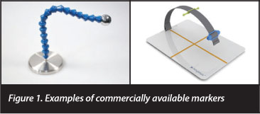
Markers have been placed beside patients but these need to be held or supported to remain in the correct plane and often disappear off the side of the image, especially in obese patients. A double marker technique has also been described.2
These markers are often quite elaborate and expensive (Figure 1).
Heinert et al3 described using the distance from the X-ray source to the anatomical structure without the use of a calibration marker.
Other methods include using a mean magnification factor determined by the radiology department,1 but this can lead to marked inconsistencies.
The hip should also be internally rotated 15 degrees, if possible, to minimise hip foreshortening and subsequent inaccuracies in femoral offset estimation.
Aim
Our aim was to develop a simple, cheap and reproducible system of calibrating digital radiographs for use in our arthroplasty unit. We have an exclusively digital system (PACS) with the necessary software available for calibration and measurements.
The study was designed to test the accuracy of placing a 20 mm ball bearing as a calibration marker between the legs of the patient during the taking of an AP pelvis X-ray.
Materials and methods
Ethical approval was obtained from UFS Ethics Committee (ECUFS 104/2012).
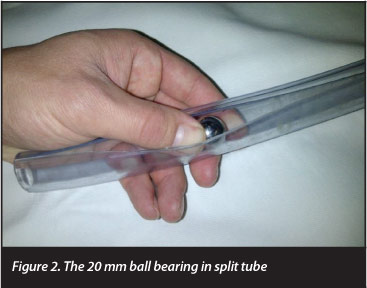
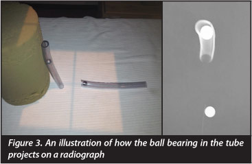
Our marker needed to be durable, washable and easy for the radiographers to position so we used a 20 mm diameter ball bearing placed in a clear plastic pipe which is split for easy manipulation (Figures 2 and 3).
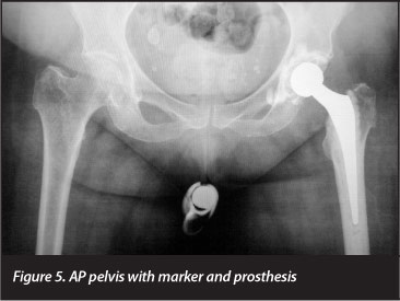
Prior to the X-ray the ball bearing was manually positioned in the pipe at the level of the greater trochanter as the patient stood against the wall (Figure 4). The patient then lay down and the tube with marker was placed between the thighs, over the undergarments during the X-ray (Figure 5). The thighs were internally rotated 15 degrees to minimise neck foreshortening, and the AP radiograph was taken.4 All our radiographers were familiar with this technique.

One-hundred-and-one digital AP pelvis radiographs were sourced from our patient records on the digital PACS. No specific sampling method was used. Radiographs were taken by radiographers on duty in the department at National District Hospital between 2009 and 2012.
The radiographs all had existing hip implants of known dimensions with a 20 mm marker between the legs (Figure 5) and documented operation reports.
All radiographs were individually calibrated and measured using our computer software on the PACS.
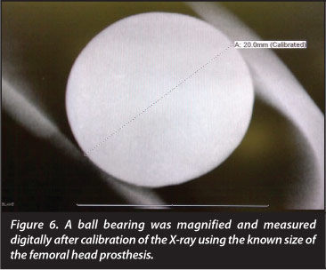
The size of the femoral head prosthesis, as documented in the patient files, was used to calibrate the image and the ball bearing marker was then measured using a digital ruler.
Measured objects were magnified as large as possible on the digital screen for more accurate readings (Figure 6).
Results
The data was collected by two researchers and analysed by the Department of Biostatistics at the University of the Free State.
Table I shows the frequencies and related percentages obtained for the 101 measurements, as well as indicating the degree of variation from the actual size of 20 mm. From this, it can be seen that the modal measurement was, in fact, 20 mm (N=11). This is further supported by a median also of 20 mm, and a mean measurement of 19.95, only 0.05 mm off the real size.

Conversely, examining the degree of variation, a total range of deviation was found from -0.9 mm (the image as measured was 0.9 mm smaller than the actual object) to 1.0 mm, again, obviously, with a mode and median of 0 mm. The mean deviation was -0.05 mm (i.e., the ball bearing was, on average, under-measured by 0.05 mm), again with the same standard deviation of 0.48 mm.
The standard deviation (around the mean of 19.95 mm) was 0.48 mm, giving a 2σ range of 18.993 mm-20.905 mm (meaning that, given a normal distribution and a sufficiently large sample, approximately 95% of all measurements would fall in this range), so that images taken with this technique could be assumed to be accurate up to 1.007 mm in 95% of all cases. It should be noted, though, that the actual range of measurements in this study extended only from 19.1 mm-21.0 mm (i.e., less than two standard deviations from the mean).
However, given the small sample size, it was deemed important to obtain a more accurate estimate of the mean itself, and thus 95% confidence intervals (CIs) for the mean were computed. This is useful, as the computation of CIs takes into account the sample size, and this can provide a more accurate estimate of what the measurements would be, given different samples. The 95% CIs for the obtained measurements lie at 19.85 mm-20.04 mm, and, interestingly, the 99% CIs were a mere 19.82 mm-20.07 mm. This means that in 99% of cases, it can be assumed that the actual obtained measurement does not differ significantly (from a statistical perspective, that is) from the actual measurement of 20 mm.
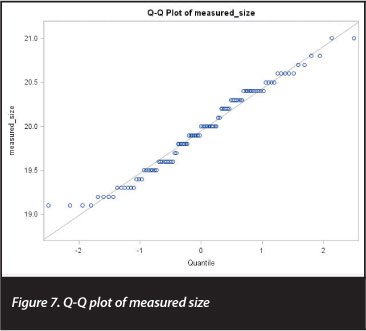
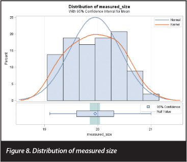
This was further corroborated by performing a single-sample, two-sided t test, comparing the obtained measurements to the actual measurement of 20 mm. This t test yielded a t statistic of -1.08 (df=100, p=0.28), confirming that the obtained measurements did not differ significantly from the actual measurement of 20 mm. The normal quantile-quantile plot shown in Figure 7 shows that the measurements were reasonably normally distributed, with a few outliers at the bottom end of the range, and Figure 8 plots the distribution of the measured sizes against the normal distribution.
Discussion
Our results confirm that, with a range of less than 2 mm (1.9 mm) over our whole sample group and a mean of 19.949 mm, this method was very accurate. This is thus a simple and accurate technique for marker placement and subsequent calibration of digital radiographs.
Possible limitations of the study include the fact that the body mass index of X-rayed patients was not taken into consideration and may be worth including in future calibration studies. Obese patients do have less prominent greater trochanters which could lead to errors in accuracy.
Secondly, although radiographers were trained and comfortable with our technique, there is the possibility of inter-observer error with respect to the tube placement.
Thirdly, questions were raised by colleagues during the study about whether patients were reluctant to allow the radiographers to place the marker between the legs.
Our results confirm that this method was very accurate
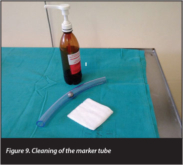
We had no formal complaints but brief pre-X-ray counselling of the patient as to the reason for the marker (e.g. greater accuracy and possibly better surgical outcomes), and the reassurance that the marker was thoroughly cleaned between uses was effective (Figure 9).
Applications
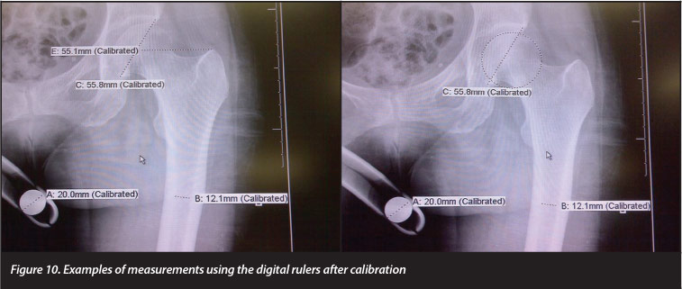
Digital measurements
Examples of digital measurements taken pre-operatively after calibration with the 20 mm ball bearing marker are shown in Figure 10.
Traditional templating
Traditional techniques using template overlay are also possible after enlarging 20 mm marker digitally to correspond with the 20 mm on the template ruler (Figure 11).

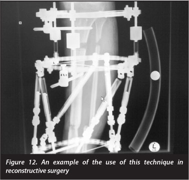
Other applications in orthopaedics
The technique is also used in reconstructive surgery (Figure 12).
Conclusion
This technique is a very simple and cost-effective means of accurately calibrating digital radiographs in arthroplasty. This method of calibration has become standard practice in our arthroplasty unit (University of the Free State Orthopaedic Department).
It has also been used by other departments for sizing orthopaedic radiographs (Figure 10).
We recommend the use of this calibration method for templating in hip arthroplasty to minimise complications such as leg length discrepancy, subsidence, dislocation or fractures.
No funding was received for the research. No benefits or funds were received in support of the study.
References
1. Brew CJ, et al. Scaling digital radiographs for templating in total hip arthroplasty using conventional acetate templates independent of calibration markers. Journal of Arthroplasty April 2012;27(4):643-47. [ Links ]
2. Baxter JA, et al. The accuracy of automatic calibration of digital pelvic radiographs using two different scale markers. Hip Int 2012;22(01):82-89. [ Links ]
3. Heinert G, et al. Digital templating in hip replacement with and without radiological markers. J Bone Joint Surg Br 2009;91:459. [ Links ]
4. Merle C, et al. Femoral offset is underestimated on anterior radiographs of the pelvis but accurately assessed on anteroposterior radiographs of the hip. J Bone Joint Surg Br 2012;94-B:477-82. [ Links ]
5. Vanin N, et al. Accuracy of digital preoperative planning for total knee arthroplasty. Tech Health Care 2010;18:335-40. [ Links ]
 Correspondence:
Dr CA Blake
Department of Orthopaedic Surgery
University of the Free State National District Hospital
Private Bag X20598
Bloemfontein 9300 South Africa
Email: drcraigblake@yahoo.com

