


Services on Demand
Article
 English (pdf)
 Article in xml format
 Article references
Indicators

Related links
-
 Cited by Google
 -
 Similars in Google
Share

 Permalink
Journal of Energy in Southern Africa
On-line version ISSN 2413-3051
Print version ISSN 1021-447X
J. energy South. Afr. vol.31 n.4 Cape Town Nov. 2020
http://dx.doi.org/10.17159/2413-3051/2020/v31i4a8480
ARTICLES
The effect of different working fluids and internal geometries on the efficiency of evacuated tube heat pipe solar collectors
Jean Gad MukunaI; Jasson GryzagoridisII
IDepartment of Mechanical Engineering, Mangosuthu University of Technology, Durban, South Africa. ORCiD: 0000-0001-5717-8246
IIDepartment of Mechanical Engineering, Cape Peninsula University of Technology, Cape Town, South Africa. ORCiD: 0000-0001-6435-2978
ABSTRACT
In this study, a heat pipe was modified with designed and manufactured inserts of specific profiles in order to investigate the effect of the internal geometries and working fluids on the efficiency of the evacuated tube heat pipe solar collector. The experimental rig was made of a mobile frame, an insulated water tank, a solar simulator and an evacuated tube heat pipe. Using an average irradiance of700 watts per square meter, the indoor tests were conducted first on a heat pipe without any working fluid (dry mode) and later on the heat pipe containing, in turn, each of the six working fluids for each of the five geometries. Results show that, when inserting different profiles in the heat pipe, there is an enhancement of the heat transfer and hence an increase in the efficiency of the evacuated heat pipe solar collector.
Keywords: thermal performance; working fluid
1. Introduction
The depletion of carbon fuels, and the battle against global warming has driven research on renewable energy. The most accessible, clean and cheap of renewable energy source is solar energy during the last 20 years, research focusing on the improvement of collection and transformation of solar energy into electricity and heat has increased significantly [1].
For water-heating purposes, solar collectors are used to convert solar radiance into thermal energy, with preference given to the flat plate collector and the evacuated tube (heat pipe) solar collector for domestic water heating applications. The selection of a solar collector is based on its thermal performance, which depends on environmental conditions, the type of material used in its construction, the shape of the collector and its positioning relative to the sun's travel [2]. Studies have shown that bad weather and unfavourable climatic conditions have a negative impact on the thermal performance of flat plate solar collectors, imposing some limitations in their usage [3]. Where cloudy conditions prevail, evacuated tube heat pipe solar collectors are preferred.
2. Evacuated tube heat pipe solar collector
Typical evacuated tube heat pipe solar collectors, as shown in Figure 1, are made of a sealed evacuated glass tube containing a heat pipe. The heat pipe is made of metal (usually copper), in which a particular vacuum is maintained to allow the evaporation and condensation of the fluid that it contains at relatively low temperature.
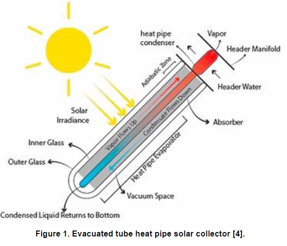
The evacuated tube is made of two borosilicate glasses. The outer glass, which receives the thermal radiations, is designed to resist environmental impacts, while the inner glass is covered with a coating to enhance the absorption of solar radiation, for minimal heat loss, and to help transmit the maximum thermal energy to the interior of the evacuated tube. The amount of heat used to heat the water depends mainly on the thermal behaviour of the heat pipe. If the performance of the heat pipe is improved, the efficiency of the evacuated tube's heat pipe solar collector will be improved as a consequence [5].
3. Heat pipe
A heat pipe is a heat transfer device made of a metal envelope, a capillary wick, and working fluid. When thermal radiations are applied to the heat pipe through the evaporator, the working fluid contained in the inner space of the heat pipe vaporises. As a result of the pressure difference between the two ends of the heat pipe, the generated vapour moves from the evaporator to the condenser, where it condenses (see Figure 2). Because of the difference of temperature between the condenser and the heat sink, the vapour will release latent heat-when condensing into liquid. The pressure developed in the capillary structure allows the liquid to be driven back to the evaporator for a new cycle of operation [6]. The high 'thermal conductivity' developed by heat pipes is attributed to the latent heat transferred by the two phases in the flow process the working fluid undergoes [7]. The thermal performance of a heat pipe depends on factors defined by the working fluid or the capillary wick structure.

3.1 Thermal performance of a heat pipe
The thermal performance of a heat pipe can be expressed by the overall heat transfer coefficient, the thermal resistance or the efficiency. Each type of heat pipe is characterised by limits that the designer or user should focus on, in order to allow the heat pipe to function and perform properly in the specific range of its application. The limits referred to take into consideration the effect of viscous friction on the vapour movement, the variation of the vapour flow rate due to speed, the permeability of the capillary wick, the risk of dry-out, and the danger of bubbles being produced during evaporation. Those limits are: viscous, capillary, entrainment, and boiling.
Except for a few external factors, such as input heat flux and tilt angle, the performance of a heat pipe depends mainly on the thermo-physical properties of the working fluid and the wick structure factors [9].
3.2 Working fluid
For the last ten years, researchers have understood the concepts behind the heat transfer principles and the flow regime phenomena of the vapour and liquid phases of the working fluid during the heat pipe operation. Relevant research has, in particular, elucidated the understanding of the impact of the working fluid on the thermal performance of the heat pipe [10]. More work has been conducted on new types of working fluid to obtain better performance. Research has been extended to study the compatibility between the working fluid and the container material, to avoid corrosion and the production of non-condensable materials [11-13]. Most importantly, for enhanced heat transfer and good flow regime, it has been discovered that the working fluid must present a high thermal conductivity, high latent heat of vaporisation, and an acceptable surface tension. In addition, a low viscosity is required for the entire range of operation temperatures [14]. Considering the properties of the fluid as listed above, the effective way to quantify the ability of a working fluid in a heat pipe to carry heat, is to compute the fluid's transport factor, or merit number, using the following formula:
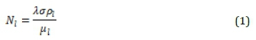
where N1 = merit number (W/m2); pl = liquid density; σ = surface tension; λ = latent heat; and = liquid viscosity
3.3. Capillary wicks
It is in the capillary wick that pressure is developed to return the working fluid to the evaporator to avoid dry-out and to allow a continuous operation of the heat pipe. Studies on various properties of wick capillary structures have been promoted, and different types of capillary structures, new technologies and materials have been developed to enhance the thermal properties of a heat pipe [15].
3.4 Concentric annular heat pipe
In addition to research on the working fluid and wick capillary on the improvement of the thermal performance of a heat pipe, some studies focused especially on the impact of a concentric annular heat pipe, which is made of two concentric pipes of unequal diameters, as depicted in Figure 3.
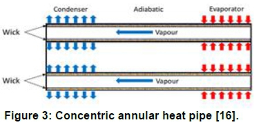
Faghri and Thomas (1989) manufactured and investigated a newly designed concentric annular heat pipe. After theoretical and experimental analyses, they discovered that the concentric annular heat pipe led to a notable increase of the heat capacity per unit area when compared to a conventional circular heat pipe [17]. Other studies have shown that a concentric annular heat pipe achieves a better thermal performance than that of a conventional heat pipe [18]. Based on results obtained from, basically, changing the geometry of the heat pipe, it was decided to investigate, in this experimental study, the impact of internal inserts of various geometries and working fluids on the performance of the evacuated tube heat pipe solar collector.
4. Objectives of the study
The objectives of this experimental study were as follows:
• To design and construct inserts of various geometries for the normal circular heat pipe. The geometries chosen were: no insert (NI), I-profile insert (II), V-profile insert (VI), triangle-profile insert (TI), and square-profile insert (SI).
• To perform tests with the combinations of internal geometries and working fluids selected in the temperature range of 200 - 500 K.
• To determine the efficiency of the heat pipe in a dry mode and the impact of different inserts on that efficiency.
• To analyse the impact of each combination of an internal geometry and each working fluid on the efficiency of the heat pipe.
5. Experimental set-up
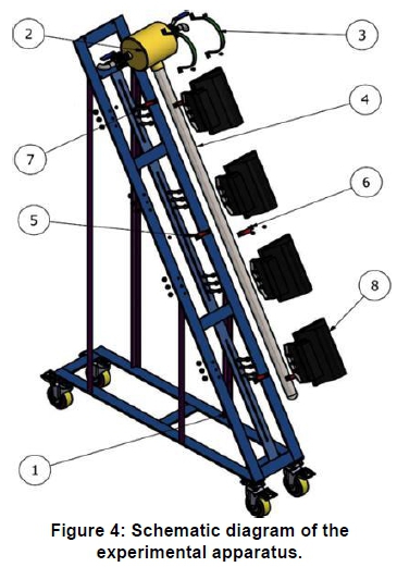
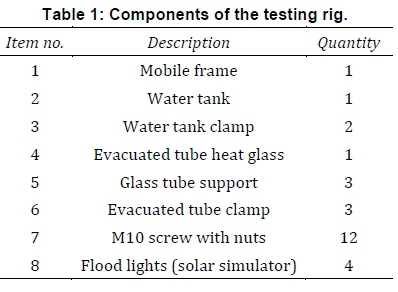
The experimental apparatus (depicted schematically in Figure 4) comprise a mobile frame, an insulated container, an evacuated tube heat pipe, and a solar simulator. The main components, as given in Table 1 are described as follows. The mobile frame, made of stainless steel, was designed to carry the entire structure during the experiments. A stainless steel reservoir (storage tank), covered with a 50 mm fibre wire in forced lagging, measuring 180 mm inner diameter and 200 mm long, was used as geyser. Fixed on the upper part of the rig, the tank was filled with four litres of water. A set of tapered British Standard Pipe (BSP) thread was used to fix the heat pipe on the water tank. The female thread of 19.1 mm was welded in the opening of the water tank, while a male thread of 20.8 mm was welded on the heat pipe. A solar simulator made of four halogen floodlights was used to supply the inlet radiations, as the rig was designed for indoors testing. The total irradiance of the solar simulator was set to a constant average value of 700 W per square metre. To adjust the irradiance of the solar simulator and control the voltage of the lights, each floodlight was connected to the outlet of a variable transformer.
5.1. Evacuated tube and heat pipe specifications
The selection of the dimensions of the evacuated tube and heat pipe was motivated by the application and availability on the market. The evacuated tube and heat pipe specifications are shown in Table 2.

5.2. Heat pipe preparation
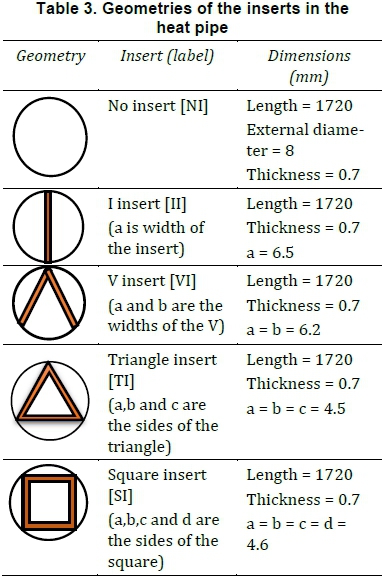
A heat pipe with five inserts of different geometries were manufactured and used in this investigation, as follows:
• The first geometry was a normal heat pipe without insert, to provide values that could be used as reference to the results from the other inserts.
• The remaining four inserts were manufactured as an I-profile, a V-profile, a triangle-profile, and a square profile (to fit tightly) in the heat pipe, as illustrated in Table 3.
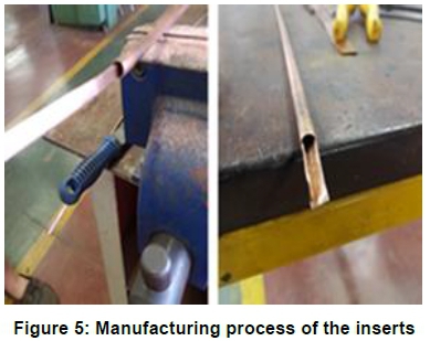
• The inserts were manufactured from a copper sheet that was 1800 mm long, 600 mm wide and 0.7 mm thick. To section the sheet (for the widths and sides of the inserts) a cutting machine was used, but manual tools were employed to construct the different profiles (see Figure 5).
5.3 Working fluid
In the range of temperature considered for water heating and based on the thermo-physical properties, the following working fluids were selected for this study: acetone, ethanol, ethyl acetate, methanol, toluene and distilled water.
6. Instrumentation
The data acquisition NI9211 (gain error +/-0.05% offset error +/-15 uV) and a chassis NI-DAQ 9189 were used for processing the temperature measurements, as shown in Figure 6. Lab VIEW was used for data visualisation, analysis and management. Four K-type thermocouples were connected to the NI 9211 module for temperature measurements. Two thermocouples were used to measure the water tank temperature while two others measured the ambient temperature. The thermocouples were calibrated while creating DA Qmax task during the building of the temperature measurement bloc diagram in Lab VIEW. The temperature of the thermocouple to be calibrated was compared with the temperature of the reference, and the value of R2 of each of the performed experience was calculated. Each channel was calibrated within the task (for an average value of R2 = 0.9956, the percentage of average error found was 1.2%). For the measurement and the adjustment of the radiation from the solar simulator, a Nanovip power meter and an MT 942 light meter were used.

7. Experimental protocol
• Immediately after the building of the rig shown in Figure 7, a dry mode test (the heat pipe without working fluid) was conducted to investigate the thermal behaviour of a heat pipe as the heat transfer conductor.
• Then the heat pipe with a specific geometry insert was filled with 10 ml of the working fluid, and a vacuum of 700 Pa was created inside the heat pipe by removing air from it.
• The evaporator side of the heat pipe was sealed with an M6x1.0 mm screw. To avoid any leakage, Loctite (sealant) was used on the screw when the heat pipe was filled with a working fluid.
• The heat pipe was screwed into the tank, which was filled with four litres of water, before locating it in the evacuated tube that was fixed to the frame by two supports.
• The average irradiance from the solar simulator was set to 700 watts per square meter, (similar to the average global horizontal irradiance in KwaZulu-Natal, South Africa as the experiment was conducted in Durban) [19]). During the experiments, temperatures were recorded over seven hours and transferred to the data acquisition system. Data were stored in an Excel spreadsheet for analysis.
• To change the working fluid, the water tank was brought down, the evacuated tube and the heat pipe were taken out, emptied of its working fluid and refilled with another fluid for a new test.
• The process was repeated for all the thirty tests corresponding to the combinations of five internal geometries and six working fluids.

8. Results and analysis
In this study, the evacuated heat pipe collector's thermal performance was expressed by the efficiency, which is the ratio between the output power based on the mass of water in the tank and its temperature difference and the input power depending on the direct radiation to the absorber area and the duration of the test. See Equation 2:
where η = efficiency; mw = amount of water in the tank; Cp = water specific heat capacity at constant pressure; tmax =water tank maximum temperature; tmin = water tank minimum temperature; Ir = direct radiation; Aa = absorber area; and t = test duration.
8.1. Tests with the heat pipe dry with insert but without working fluid.
Table 4 presents the results of the tests in the dry mode for five internal geometries.
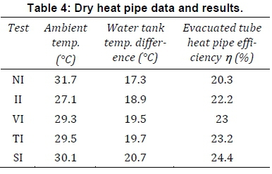
Figure 8 illustrates the increase in efficiency from 20.3% to 24.4% during the dry mode tests while using the inserts from NI to SI. The increase can be ascribed to the rise in mass and the increase in heat transfer between the tube and the insert generated by the points of contact of the insert's sides with the circular tube around it.

8.2. Tests with the heat pipe containing various working fluids
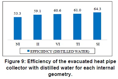
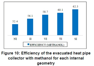
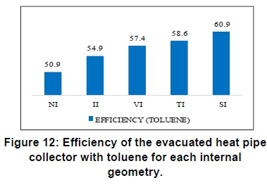
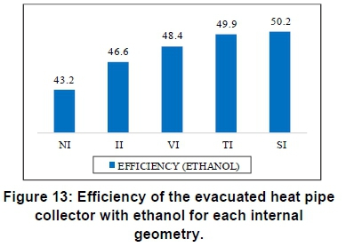
Figures 9 to 14 portray the increase in efficiency for different working fluids combined with different geometries. The same trend observed on the dry mode was noted with the heat pipe containing distilled water for the range of no insert (NI) to the S insert (SI). The same tendency, i.e. showing an increase of efficiency when moving from NI to SI, is observed for the heat pipe containing, in turn, methanol, acetone, toluene, ethanol and ethyl acetate.


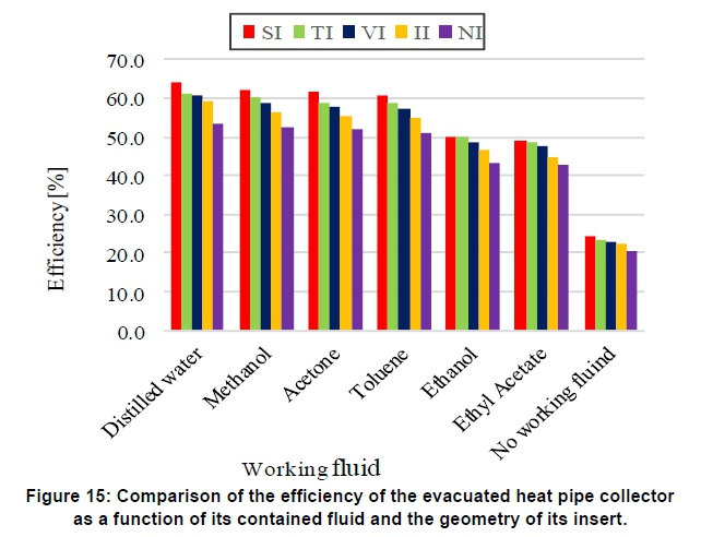
8.3 Comparison of the efficiency of the evacuated heat pipe on the basis of the contained fluid and geometry of its insert
When comparing the efficiency of an evacuated heat pipe collector with an insert with the efficiency of a conventional one without any insert, the efficiency with insert is higher, as seen in Figure 15. It can also be noted that the different internal geometries filled with distilled water present the highest efficiencies when compared to other working fluids. These observations show that the efficiency depends on the working fluid contained in the heat pipe but is also enhanced by the geometry of the insert.
The number of surface areas of the insert impacts positively on the efficiency of the evacuated heat pipe because it increases the heat transfer by convection between the insert and the vapour moving from the evaporator to the condenser. As an example, when using distilled water as a working fluid, the NI experiment produced an efficiency of 53.3%, the II 59.1% and the SI (which has four points of contact and eight surfaces), 64.3%.
The difference in the levels of efficiency attained by the evacuated heat pipe is justified by the ability of each working fluid used, to transport heat, which is known as the merit number.
8.4 Merit number and efficiency
The merit number of each working fluid used in this study is displayed in Table 5, matched to the maximum efficiency attained. Distilled water appears to be the best working fluid in the temperature range of 293.15-393.15 K.

9. Conclusion
In this study, a typical heat pipe was modified by the insertion of different profiles, in order to evaluate the effect of the internal geometry on the thermal performance of the evacuated heat pipe collector. Each internal geometry was tested with six working fluids plus the dry mode, producing 35 combinations.
The following conclusions can be drawn from this study:
• The efficiency of the evacuated heat pipe collector without insert is lower than the efficiency of the one with inserts.
• In dry mode, when using different inserts, there is an increase in the efficiency of the evacuated heat pipe collector - perhaps due to the increase in the mass in the heat pipe.
• When the heat pipe contains a working fluid, the efficiency of the evacuated heat pipe collector is higher than that of the dry mode, because of the mass transfer of the working fluid carrying the heat that is enhanced by convection from the internal surfaces of the inserts.
• For all the geometries, distilled water gives the highest efficiency for the evacuated heat pipe collector.
Author roles
Jean Gad Mukuna: Experiments and data collection, interpretation of results, and manuscript write-up. Jasson Gryzagoridis: Research formulation, supervision and editing.
References
[1] Kopnina, Η., 2016. Energy policy in the European Union: Renewable energy and the risks of subversion. In Governance and security issues of the European Union (pp. 167-184). TMC Asser Press, The Hague. https://doi.org/10.1007/978-94-6265-144-9_10 [ Links ]
[2] Ayompe, L.M. and Duffy, Α., 2013. Thermal performance analysis of a solar water heating system with heat pipe evacuated tube collector using data from a field trial. Solar Energy, 90:17-28. https://doi.Org/10.1016/j.solener.2013.01.001 [ Links ]
[3] Choi, Y., 2018. An experimental study of the solar collection performance of liquid-type solar collectors under various weather conditions. Energies, 11(7): 1626. https://doi.org/10.3390/enll071626 [ Links ]
[4] Elsheniti, M.B., Kotb, A. and Elsamni, 0., 2019. Thermal performance of a heat-pipe evacuated-tube solar collector at high inlet temperatures. Applied Thermal Engineering, 154:315-325. https://doi.Org/10.1016/j.applthermaleng.2019.03.106 [ Links ]
[5] Jafarkazemi, F. and Abdi, H., 2012. Evacuated tube solar heat pipe collector model and associated tests. Journal of Renewable and Sustainable Energy, 4(2): 023101. https://doi.org/10.1063/L3690958 [ Links ]
[6] Shafieian, Α., Khiadani, M. and Nosrati, Α., 2018. A review of latest developments, progress, and applications of heat pipe solar collectors. Renewable and Sustainable Energy Reviews, 95:273-304. https://doi.Org/10.1016/j.rser.2018.07.014 [ Links ]
[7] Sabiha, M.A., Saidur, R., Mekhilef, S. and Mahian, 0., 2015. Progress and latest developments of evacuated tube solar collectors. Renewable and Sustainable Energy Reviews, 51:1038-1054. https://doi.Org/10.1016/j.rser.2015.07.016 [ Links ]
[8] Byon, C, 2016. Heat pipe and phase change heat transfer technologies for electronics cooling. Electronics Cooling. https://doi.org/10.5772/62328 [ Links ]
[9] Reay, D., McGlen, R. and Kew, P., 2013. Heat pipes: theory, design and applications. Butterworth Heinemann. [ Links ]
[10] Peyghambarzadeh, S.M., Hallaji, H., Bohloul, M.R. and Aslanzadeh, N., 2017. Heat transfer and Marangoni flow in a circular heat pipe using self-rewetting fluids. Experimental Heat Transfer, 30(3): 218-234. https://doi.org/10.1080/08916152.2016.1233148 [ Links ]
[11] Manimaran, R., Palaniradja, K., Alagumurthi, N. and Velmurugan, K., 2012. An investigation of thermal performance of heat pipe using Di-water. Science and Technology, 2(4): 77-80. https://doi.Org/10.5923/j.scit.20120204.04 [ Links ]
[12] Kuroda, M., Chang, J.Y., Gwin, P., Mongia, R., Kim, CU., Cabusao, G.P., Goto, K. and Mochizuki, M., 2014. Development of aluminum-water heat pipes. Heat Pipe Science and Technology, An International journal, 5(1-4). https://doi.org/10.1615/HeatPipeScieTech.v5.il-4.110 [ Links ]
[13] Anderson, W.G., Rosenfeld, J.H., Angirasa, D. and Mi, Y., 2004, February. Evaluation of heat pipe working fluids in the temperature range 450 to 700 K. In AIP Conference Proceedings (Vol. 699, No. 1: 20-27). American Institute of Physics. https://doi.org/10.1063/L1649553 [ Links ]
[14] Franchi, G. and Huang, X., 2008. Development of composite wicks for heat pipe performance enhancement. Heat Transfer Engineering, 29(10): 873-884. https://doi.org/10.1080/01457630802125740 [ Links ]
[15] Mustaffar, Α., Phan, A.N., Reay, D. and Boodhoo, K., 2019. Concentric annular heat pipe characterisation analysis for a drying application. Applied Thermal Engineering, 149:275-286. https://doi.Org/10.1016/j.applthermaleng.2018.12.047 [ Links ]
[16] Faghri, Α., 1989. Performance characteristics of a concentric annular heat pipe: Part 2-Vapor flow analysis. Journal of Heat Transfer (Transactions of the ASME (American Society of Mechanical Engineers), Series C); (United States), 111(4). https://doi.Org/10.1115/l.3250796 [ Links ]
[17] Nouri-Borujerdi, A. and Layeghi, M., 2005. A review of concentric annular heat pipes. Heat Transfer Engineering, 26(6): 45-58. https://doi.org/10.1080/01457630590950934 [ Links ]
[18] Zawilska, E. and Brooks, M.J., 2011. An assessment of the solar resource for Durban, South Africa. Renewable Energy, 36(12): 3433-3438. https://doi.Org/10.1016/j.renene.2011.05.023 [ Links ]
Corresponding author: 3 Scantz Place, Durban, South Africa; email: mukunaj@mut.ac.za

