


Services on Demand
Article
 English (pdf)
 Article in xml format
 Article references
Indicators

Related links
-
 Cited by Google
 -
 Similars in Google
Share

 Permalink
Journal of Energy in Southern Africa
On-line version ISSN 2413-3051
Print version ISSN 1021-447X
J. energy South. Afr. vol.31 n.3 Cape Town Aug. 2020
http://dx.doi.org/10.17159/2413-3051/2020/v31i3a8752
ARTICLES
Design of an electrostatic precipitator for a novel bituminous coal-fired circulating fluidised bed combustion power plant in Namibia
Eliaser T. NghishiyelekeI, IV; Vallentinus M. KembaII, V; Alexander M.S. EndundeIII; Melvin M. MashingaidzeIII, *
IMechanical and Industrial Engineering Department, Faculty of Engineering and Information Technology, University of Namibia
IIElectrical Engineering Department, Faculty of Engineering and Information Technology, University of Namibia
IIIMining and Metallurgical Engineering Department, Faculty of Engineering and Information Technology, University of Namibia
IVGeneration Capital Projects, Generation, NamPower
VWire Business, Transmission, NamPower
ABSTRACT
Coal-fired power plants utilising fluidised bed technologies emit copious amounts of fly-ash, which is harmful to people owing to its particulate nature. A planned 300 MW power plant will have an electrostatic precipitator (ESP) for fly-ash emissions control, in line with power generation industry best practices. This ESP should meet a fly-ash emission limit value < 50 mg/Nm3. This paper details the design process and resultant technical specifications of a cold-side, single-stage, and plate-wire dry ESP designed for the power plant. The ESP will consist of twin-chambers with quadruple-fields (2 x 4 x 315 m3) and octonary bus-sections independently energised by individual high-frequency three-phase switched integrated rectifiers (70 kV, 800 mA) to maximise ionisation. Dynamically balanced, single-impact, tumbling hammer rappers (857.5 rpm) will dislodge fly-ash from the collector plates into mass-flow wedge-shaped hoppers. A specific collection area (> 56.9 m2/m3/s) and an ESP index (> 709.2 (kV/cm)2m2/m3/s) should guarantee a collection efficiency ( r\ > 99.5 %) and the specified emission limit value at 100 % boiler capacity and normal operating conditions (gas velocity < 2.4 m/s; gas temperature < 137 °C; fly-ash loading < 10 000 kg/Nm3; resistivity < 1010 (Ω -cm). The design was successfully verified in principle using the validation square method, in conjunction with the leading comparable historical case studies approach. It is recommended to simulate ESP designs using suitable programs like Comsol Multiphysics and construct a pilot plant before attempting scaled-up construction and commissioning.
HIGHLIGHTS:
• A cold-side, single-stage plate-wire dry ESP system designed.
• Theoretical collection efficiency in excess of 99.5%.
• High-frequency, three-phase switched integrated rectifiers to be used for ionisation.
Keywords: cold-side dry ESP; coal fly ash; specific collection area; emission limit value; validation square
1. Introduction
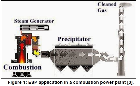
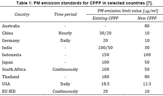
Electrostatic precipitators (ESPs) are highly efficient (η> 99.5 %), and reliable dust collectors [1, 2, 3, 4, 5, 6], best suited for fly-ash emissions control in industrial combustion processes (see Figure 1, such as coal-fired power plants (CFPPs), which inherently emit significant amounts of fly-ash (PM10 and PM2.5) and aerosols (PM0.1), adversely affecting public health. Subsequently, stringent particulate matter (PM) emission standards are implemented globally (see Table 1, to curtail reasonably foreseeable emissions and thereby curb cumulative health effects.
To keep to very low emission limit values (ELV), new ESPs are nowadays designed with higher collection efficiency (>99.9%) [1]. This implies that the ESP should collect more fine particles (PM2.5) economically. As such, several cost-effective state-of-the-art techniques have been developed in recent years, including use of modern power supplies and advanced controls to optimise fine particle collection and enhance ESP performance and reliability.
1.1 Case study: Coal-fired power plant to be constructed at Arandis in Namibia
The proposed CFPP (300 MW) will use a circulating fluidised bed (CFB) boiler with an ESP downstream, as practicable emissions control measures [8]. The plant will burn coal of about 1 wt% moisture. Considering that Arandis is in the arid Namib Desert, by the time stockpiled coal is pulverised and combusted in CFB, the moisture content would have dropped to nearly 0%. This implies that the flue gases would have very low H2O partial pressure. The combination of CFB and ESP technologies, as presented in Error! Reference source not found.Table 1 promotes low emissions [9], so the plant could possibly meet emission standards without the need for other pollutant removal systems, such as flue gas desulphurisation or selective catalytic reduction (FGD/SCR). However, with ELVs expected to become even lower in future due to tightening emission requirements, an integrated emission control system (ESP + FGD/SCR) would be highly recommendable as per current industry practice.
However, the preferred ESP technology and the desired collection efficiency have not been specified. Furthermore, the only existing CFPP in Namibia, NamPower Van Eck power station (120 MW), uses multi-stage cyclones rather than ESPs. Thus, there are no utility-scale coal fly-ash ESPs in the geographical locality which could be used for a pilot study, implying a gap in fly-ash ESPs expertise in Namibia. The ELV of Van Eck power station is unknown but it is useful to note that the first power generation units were commissioned in 1972 with the fourth coming online in 1979. If the age of the plant is considered against the backdrop of flue gas cleaning using cyclones which cannot meet strict gaseous emissions standards, then it is conceivable the plant emits particulates well in excess of the ELV.
This conceptual design work therefore attempted to establish principal ESP engineering performance specifications, necessary for achieving the desired ELV (< 50 mg/Nm3 at 6% O2), as a way to bridge the expertise gap. Obtained performance data may be considered in development of technical summaries of new pilot-scale ESPs of comparable utility generators, at the plant design stage.
1.2 ESP fundamentals and technologies
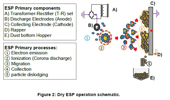
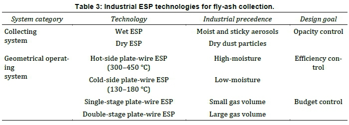
As electromechanical devices, ESPs use electro-hy-drodynamic induced turbulence flow to migrate particulates across the flue gas stream onto collecting electrodes [1, 3, 10]. In dry ESPs (see Figure 2, mechanical or electrical rappers are used to impart periodic vibrations or impacts onto collecting surfaces to dislodge dust accumulations into bottom hoppers. In wet ESPs, reticulated wash sprays wash off dust accumulations, which are then conveyed to a temporary storage prior to appropriate disposal. Based on ESP technological surveys, it could be inferred that existing industrial ESP technologies, summarised in Table 3 are categorised based on mutually inclusive multivariable system processes. These are:
• the collecting system - based on dust removal modes; and
• the geometrical operating system - based on flue gas temperature, dust ionisation, and collecting electrodes configuration.
2. Design process
2.1 Conceptual design
Multivariable conception decision making (MCDM) matrices were formulated and used for technology selection.
2.1.1 Collecting system technology selection
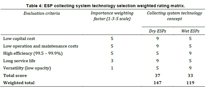
The MCDM matrix presented in Table 4 was deployed to determine the most suitable fly-ash removal mode, resulting in the dry ESP being selected over the wet ESP. The competing solutions were scored with a 1-5-9 procedure: A '1' score meant the solution was much worse than a hypothetical baseline, a '5' indicated parity with the baseline, and a score of '9' meant it was better than the baseline.
2.12 Operating system geometry selection
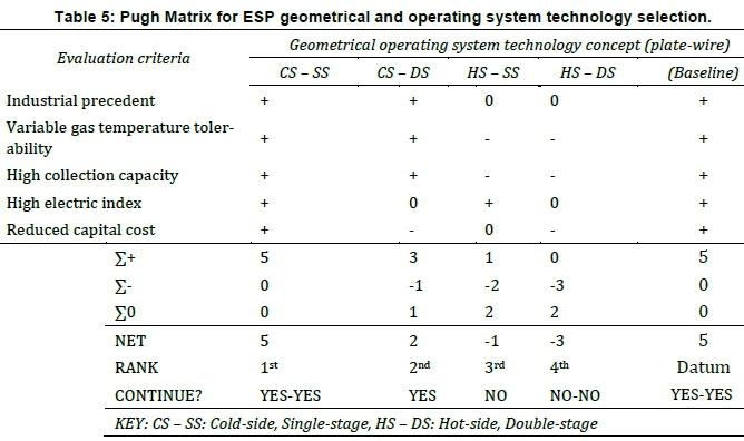
It was assumed the ESP would be placed upstream of the combustion air pre-heater, before the induced draft (ID) fan, as in recent CFPP industrial precedents. In this case, the gas temperature reduces below the sulphuric acid dew point, and the fly-ash resistivity to low ranges (1 x 10⁷ - 2 x 10¹⁰ Ω-cm). Resultantly, the sulphur trioxide (SO3) condenses and adheres to aerosols, thereby increasing the PM2.5/PM10 ratio and substantiating high-probability collection efficiency. The Pugh Matrix, presented in Table 5 was deployed to determine the most suitable geometrical technology of the four plate-wire ESPs listed in Table 3
Based on the Pugh Matrix, the CS-SS plate-wire ESP was the preferred geometrical technology, thus, since the flue gases are expected to be dry, making it a CS-SS plate-wire dry ESP.
2.2 Detailed design and sizing
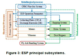
The detailed design was executed based on a multi-disciplinary engineering point of view, depicted in Figure 3 The Deutsch-Anderson equation [3, 10], Equation 1, including its derivatives, was used to estimate the specific collection area (SCA), Equation 2, required to attain a presumed collection efficiency (դESP = 99.5%).
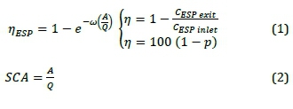
where A = Collection surface area; [m2]; ш = Particle-migration velocity [cm/s]; Q = Gas flow rate [m3/s]; CESPinlet= Inlet dust concentration [mg/ Nm3]; CESPexit = Outlet dust concentration [mg/ Nm3]; and p = Penetration.
Industrial precedent design data, summarised in Table 6 obtained from recent ESP developments, were adopted from literature [3, 6, 11].
2.2.1 Ancillary systems (a) Fuel characterisation
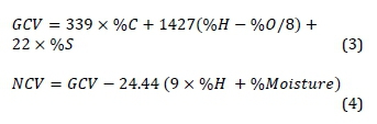
Elemental compositions (dry basis wt%) of coal, summarised in Table 7 were characterised from ultimate analysis (ASTM D3176 - 15) [6], using the case study data (ash: 15% and sulphur: 3.0%). The coal grade was classified based on the ASTM D388 classification system. The Dulong formula (dry basis wt%), presented by Equations 3 and 4, was used to estimate the gross calorific value (GCV) and net calorific value (NCV) of the coal.
2.2.2 Flue gas characterisation
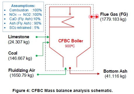
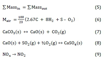
A mass balance analysis (dry basis wt %) was performed for the CFB boiler system presented in Figure 4 Steady state fluidising conditions were assumed [6]. Volatile matter constituents, reported in Table 8, were determined using Equation 5. The mass of primary air (in kg) required for a complete combustion was calculated using Equation 6. The thermodynamic equilibrium of calcining, indirect sulphating of limestone, and nitrogen oxides (NOx) suppression under complete air-combustion conditions were applied, as expressed in Equations 7-9:
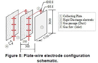
2.2.3 Collecting electrodes
The plate-wire configuration, presented in Figure 5 with rigid spiked pipe discharging electrodes, was recommended and designed [6]. The adopted design data were formulated from literature surveys [3, 6]. The total number of collecting plates per field was determined using Equation 10:
2.2.4 High-voltage supply and controls
High frequency (50 kHz), three-phase, high voltage DC (70kV - 100 kV) switched integrated rectifiers (SIR), with built-in SQ-300i automatic voltage controls (AVCs) XM algorithms, were highly recommended over conventional single-phase T-R sets [5]. These algorithms combine advanced optimum ESP control with sophisticated diagnostic features, including high speed and accuracy. This enables the AVC XM to intelligently respond to sparks and maintain high power supply reliability as opposed to the conventional single-phase TR, which is essential for meeting electrical requirements for fine particle (PM2.5) charging and collection [1]. Each electrical field (bus-sections) is independently energised by an individual SIR to maximise corona discharge whilst optimising the ESP collection efficiency at decreased parasitic load. The AVC XM includes all the standard features expected for adequate controls, such as energy management, power reduced rapping, back corona detection, and background power settings, among others.
ALSTOM was considered as the prospective supplier of the SIR [5]. Thus, each SIR unit comprises a switched mode power supply (SMPS), a controller with pre-installed EPIC III software, a liquid cooling system and motor groups for the rappers and hopper heaters. The combination ensures continuous power adjustments with variable inlet fly-ash loading and resistivity. Energisation conditions were developed by determining the minimum, average and maximum electrical operating parameters, presented hereafter [10].
(a) Corona discharging conditions
These are the minimum electrical operating conditions necessary to realise energisation onset. These include corona onset electric field (E0), corona onset voltage (V0), average corona current (Ic), corona power (Pc), and the total ESP power (PESP); determined through Equations 11-14:

(b) Maximum electrical operating conditions
These include the maximum electric field (Emax), sparking field strength (Es) and maximum voltage (Vmax); determined through Equations 15 and 16:
(c) Average electrical operating conditions
These include average voltage (Vavg), average electric field (Eavg), charges acquired by the particles, and ESP index; determined through Equations 17-19:
where [17] s. g = Flue gas specific gravity w.r.t to air at 293 K and 1 atm [0.74]; rw= radius of the electrode wire [0.009 m]; ƒ = Wire roughness factor [0.6]; W = ESP plate-wire spacing [150 mm]; d = Electrode wire diameter [191 mm]; V = Applied voltage [V]; Minimum voltage [V]; Peak voltage [V]; K = No back-corona constant [1.75]; dp= Particle diameter £16 mm]; e0= Vacuum permittivity [8.85 X 10⁻¹² .m]; and e = Particle dielectric constant w.r.t vacuum [3.7].
(d) Switched integrated rectifiers (SIR) unit sizing
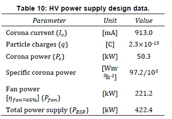
The technical specifications of SIR units should be closer to the ESP maximum operation voltage (Kmax) and corona power (Pc) [5]. The SIR specifications were therefore equated to the secondary ratings of the high-frequency transformer, presented in Table 9 These were used to determine the primary ratings thereof, using the power transfer theory, represented by Equation 20:
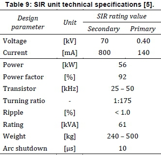
Table 10 summarises the obtained electrical design data, corresponding to the electrical circuit schematic diagram presented in Figure 6
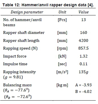
2.2.5 Collecting electrode rappers
Horizontal side mount, single impact tumbling hammer rappers, powered by a parallel roller chain drives, were recommended and designed [4]. Tumbling hammer rappers provide a high rapping intensity and frequency flexibility. This is optionally practical and highly desirable for fly-ash capture from variable dust concentration flue gas streams. The chain drive mechanism was found to be the most economic option that best suits short central distances (< 8 m) applications, at maximum linear velocity < 25 m/s and maximum power < 110 kW. Its relatively lower spacing requirement, higher power transmission efficiency (98%), optimum performance under adverse operating conditions (shock loadings, high temperatures and high pressures), lower maintenance costs, and easy retrofitting are additional advantages over other alternatives.
(a) Tumbling hammer dynamic analysis
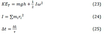
When a tumbling hammer, rigidly coupled onto a drive shaft, drops due to gravity and hits a stationary anvil beam, it is assumed to undergo a rotational-translation motion about a fixed axis [4]. Thus, the principle of rigid body dynamics was applied [12], using Equations 21-25, with the following assumptions:
• the hammer gains both the potential and kinetic energy during succession rapping;
• the hammer/anvil impulsive motion is linear and completely elastic; and
• no excessive re-entrainment or rapping losses.
where ա) = angular speed [rad/s]; g = acceleration of gravity [9.8 m/s2]; h = hammer height [m]; l = moment of inertia [kg m2]; a = angular acceleration [rad/s2]; v = hammer linear impact velocity [m/s]; m = mass of a hammer [kg]; r = distance centre of mass [m]; x = Torque [Nm]; KET = Total kinetic energy [J]; and Δt = Angular impulse [s].
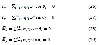
(b) Drive shaft dynamic balancing
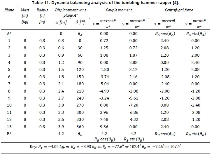
During succession rapping the drive shaft is subjected to pulsating centrifugal forces [4]. This results in undue vibrations and dynamic unbalance (U). To counter vibrations, due to shaft deflection by imbalance centrifugal forces (F) and shaft twisting by imbalance centrifugal moments (M), a two-plane balancing technique was applied herein, using the graphical method. Two outboard balancing planes (A* and B*) were applied, as illustrated in Figure 7 with plane A* being the reference plane.
The balancing of rotating masses was done on both the vertical plane (yz-plane) and horizontal plane (xy-plane) [4], as summarised in Table 11 using diagrams depicted in Figure 7 The horizontal (Fx , Mx) and vertical components (Fy , My) were determined using Equations 26-29:
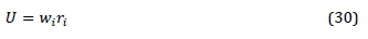
The product of the weight (w) and radius (r) of a rotating mass denotes an unbalance (kg ■ m), given by Equation 30:
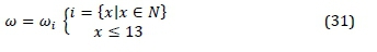
However, for a dynamically balanced drive shaft, shaft mounts are subjected to uniform angular speed (ш) = шi), irrespective of individual angular displacements (0i ≠ 0i+1). This is represented by Equation 31:
An arithmetic sequence, represented by Equation 32, was used to denote the angular position (0i) of individual hammers.
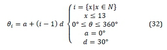
Figure 8(a) shows that the high spot is along the m13-plane of rotation, toward the support bearing B (see Figure 7, (Mmax = 9.36 kg m2). Besides, only the horizontal couple component (x) is active, and thus excites periodic vibrations. The vertical couple component has no explicit effect, as it is counteracted by the weight of the rigid body, hence excites dormant vibrations.
To curb the turning effect on the support bearngs, addition of a heavier balancing mass is required along the balancing plane B* than A* (RB > RA). This alteration better aligns the mass centre and the central principal axis with the axis of rotation. Figure 8(b) illustrates the case of a dynamically balanced rapper, as opposed to Figure 8(a).
(c) Drive shaft sizing
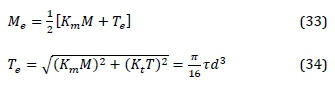
To determine the shaft diameter, with sufficient endurance to withstand the resultant vibrations, the combined loads; equivalent moment (Me) and torque (Te), were determined [4, 13, 14], using Equations 33 and 34:
To minimise shaft weight, whilst optimising the endurance, short inline-twin rapper drive shafts (2 x 4.2 m) were recommended per mechanical field, over a longer (1 x 8.4 m) single drive shaft. The technical specifications developed are as presented in Table 12
(e) Chain drive system
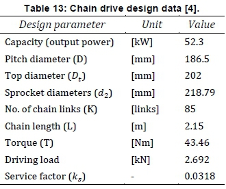
The maximum velocity, required for effective dis-lodgment of accumulated fly-ash cake from collecting plates, was found to be 15 m/s [4]. Using design tables, the technical specifications of the roller chain drive system were developed, and were as presented in Table 13
2.2.6 Dust collection hopper
Mass-flow wedge-shaped hoppers were recommended and subsequently designed using Jenike's design method (DIN 1055-1980 standard) [4, 15].
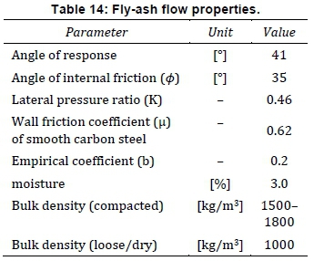
(a) Numerical characterisation of flowability Since the coal supplier was still unconfirmed at the time, estimates of fly-ash flow properties were obtained from literature [4, 16, 17, 18]. These properties are as presented in Table 14
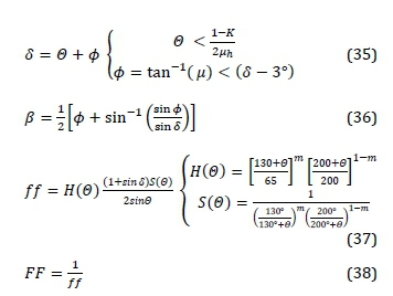
The hopper apex half-angle (0) was determined by interpolating Jenike's hopper design charts. The flow parameters, including the flow factor (ƒƒ), flow function (FF), geometry factors or arch thickness empirical parameters (ß, H(0), S(0)) were determined numerically using Equations 35-38:
(b) Hopper structural analysis
Slice element method and cohesive arching analysis techniques illustrated in Figure 9 were applied to assess the stresses and pressures exerted by the cohesive bulk material onto the hopper wall [4, 16].
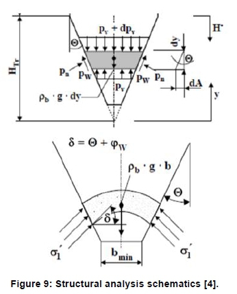
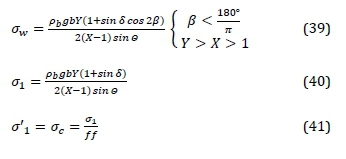
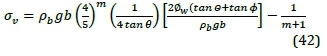
The principal stresses at consolidation, including the wall normal stress (aw), major principal consolidating stress (σ1) unconfined yield strength (σ1 = σc) and average vertical stress (σv) were analytically determined through Equations 39-42:
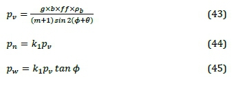
The pressures exerted on the hopper wall, including the discharging pressures (pv), the normal pressure (pv) and tangential pressure (pw), were determined through Equations 43-45:
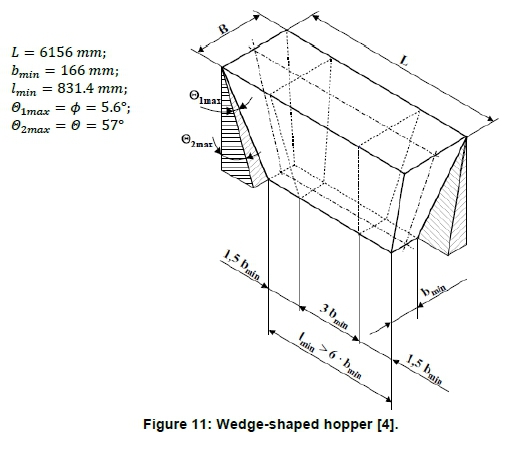
(c) Hopper geometry
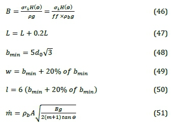
The hopper geometry was optimised to minimise cohesive arching [4]. Critical hopper dimensions [19], including the inlet width (B), inlet length (L), discharge width (bmin), slot discharging width (w), and slot discharging length (Z), as well as the discharge rate (m) were determined through Equations 46-51:
Obtained technical specifications, including the normal - shear stress (σ-t) diagram are as presented in Figure 10 and Figure 11
2.3 ESP material specifications
A moderately corrosive working environment was assumed, due to the expected low SO2 concentration (0.025% SO2) in the flue gases [6]. Thus, carbon steel structural components were recommended for their low cost, as a minimum; apart from the collecting electrodes, casing insulators and rapper shafts. The specific material specifications are as summarised in Table 15
3. Results and discussion
3.1 The CFPP and ESP design specifications
A simplified process flow diagram (PFD) of the CFPP and ESP system, presented in Figure 12 was developed using Microsoft Visio 2016. The PFD demonstrates the CFPP component-process interfacings. Table 16 summarises the developed ESP engineering design specifications. A specific collection area (SCA) of > 15.8/1000 m2/m3/h and an ESP index value of > 709.2 (kV/cm)2m2/m3/s were found to guarantee the achievement of a collection efficiency > 99.5% and an emission limit value (ELV) > 50 mg/Nm3 at 6% O2, if a bituminous coal with the composition in Table 6 is used.
3.2 Design validation
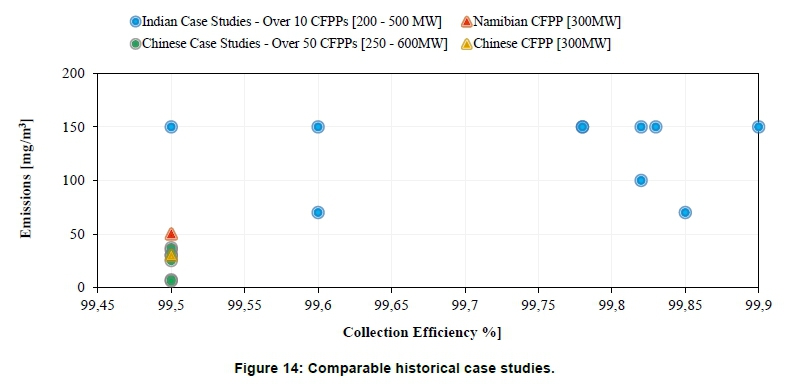
Since there was no installed ESP in Namibia that could be used for a pilot ESP study, field-test based physical data, adopted from successful new ESP developments and recent upgrades of comparable historical case studies, were used to validate this CS-ESP design. Performance data generated from 'over 50' industrial full-scale cold-side ESPs recent (2012/2013) upgrading programme (250-600 MW) in China [1] was used as comparable historical case studies.
This programme was launched to primarily improve efficiency of existing CFPPs, and to meet even more stringent emission legislations (ELV < 30 mg/ Nm3) when burning over 122 Chinese coal variants. In this paper, the validation square method [20] (see Figure 13, was used to validate the designed ESP. Case studies in India [21] and China [1] were compared to the current design. However, as is evident from Figure 14 the current design fitted the Chinese designs better than the Indian designs. Thus, the Chinese case studies were considered as the leading comparable historical case studies (LCHC).
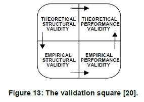
Technological based input parameters (including fly-ash collecting mode, field energisation, rapping configuration, and operating temperature) were analysed to verify the performance validity of the design of interest. Extrapolated performance curves, based on the coal quality, flue gas temperature, fly-ash loading, SCA, ESP index, ELV, collection efficiency, and corona power density were compared with the LCHC to affirm the structural validity.
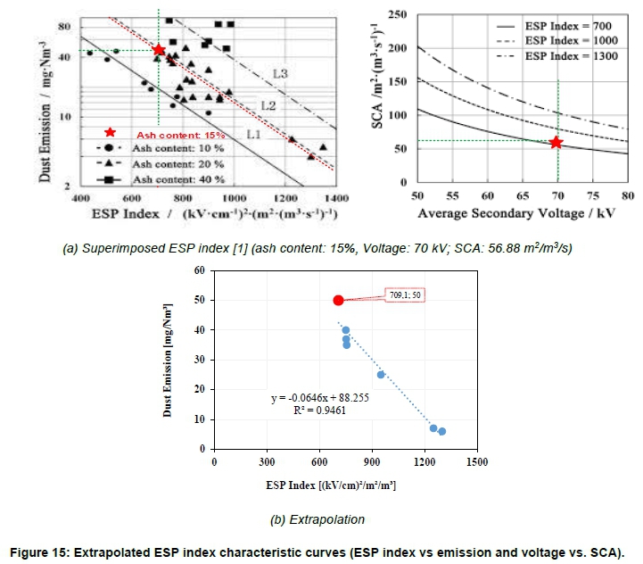
(a) Structural validity
The structural validation of the ESP design was done by superimposing the obtained ESP index value (709.2 (kV/cm)2m2/m3/s), operating voltage (70 kV) and SCA value (56.88 m2/m3/s) necessary for achieving an ELV < 50 mg/Nm3 at 6% O2 when burning low-ash (15%) bituminous coal, onto characteristic curves of the LCHC [1], and linearly extrapolating assuming ceteris paribus as illustrated in Figure 15 Thus, this ESP design exhibits conservative electrical performance characteristics in all respects.
(b) Performance validity
However, to address underperformance due to variable fly-ash resistivity, while using the same rapping mechanism and SIR unit, the flue gas temperature must be reduced from 137°C to 100°C. In this case, and as depicted in Figure 16 the side-mounted rapper designed best suits the design application of interest, even at lower temperatures.
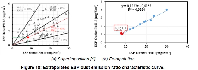
After superimposing the obtained emission performance data onto performance curves of the LCHC [1], for comparison, it is evident from Figure 18 that the selected case study fitted well the current ESP design. Thus, it was inferred that the designed ESP will attain a PM2.5/PM10ratio of 12% at an ESP Index > 700 (kV/cm)2m2/m3/s.
3.3 The mock-up ESP
A single-chamber mock-up ESP (LxH xW: 900 x 600 x 800 mm), with a single bus section was fabricated to showcase the ESP primary components interfacing. This comprised of a tumbling hammer rapper, a wedge-shape hopper, 8 collecting plates with a gas passage of 100 mm, 16 rigid discharge electrodes (010) and a modelled T-R set. Most components were fabricated from carbon steel, with welding as the main joining method. Photographs of the mock-up being constructed and the final model are displayed in Figure 19
4. Conclusion and recommendations
A cold-side, single stage, plate-wire, dry ESP was deemed appropriate for the forthcoming power plant and subsequently designed with specific focus on ESP capacity, number of chambers, fields, bus-sections, total collection area, specific collection area, aspect ratio, corona power, corona voltage, corona current, specific corona power, total power supply, SIR unit size, number and size of collecting plates, number and size of discharge electrodes, hopper specifications, and collecting electrodes rapper system. The final design of a twin-chamber, quadruple-field ESP with octonary bus-sections was realised through application of numerous mathematical equations, including the Deutsch-Anderson equations. The performance specifications (geometrical, electrical, and technological) developed should enable the ESP to produce the desired collection efficiency (99.5%) required to meet the regulatory emission limit (50 mg/Nm3 at 6% O2). Extrapolated performance characteristic curves, developed from historical case studies of comparable fly-ash pilot-ESPs of the CFPP global leaders, notably China, were adopted.
The design was successfully validated using the validation square in conjunction with the leading comparable historical case studies approach, which is a novel method for validating theoretical designs. Obtained performance specifications fitted well on existing curves, thus the ESP design conforms to the current performance expectations for these particulate matter control devices. The complete design specifications can be regarded as baseline design values for the development of a pilot fly-ash ESP for the particular power plant in Namibia and other comparable power plants. Future ESP designs can be enhanced by relevant simulation programs like Comsol Multiphysics in combination with a pilot-plant study before commencing plant scale construction and installation.
Acknowledgements
This work was accomplished with full support from the Faculty of Engineering and Information Technology, University of Namibia.
Author roles
E.T. Nghishiyeleke: Designing the ESP rapping system and ash collection hoppers; construction materials selection and bill of quantities; ESP model construction; validation of the ESP design; writing and revising the article drafts. V.M. Kemba: Designing the ESP high voltage supply system and voltage control system; specification of power supply and voltage control systems equipment; ESP model construction.
A.M.S. Endunde: Characterising the flue gases to be cleaned by the ESP; designing the ESP: writing Matlab code for a process control program for the circulating flu-idized bed and ESP; ESP model construction. M.M. Mashingaidze: Conceiving and coordinating the mul-tidisciplinary project; partially funding ESP model construction; identification of journal for publication; writing and revising the article drafts; correcting the article after review and copyediting; proofreading galleys.
References
Y. Huang, S. Li, Q. Zheng, X. Shen, S. Wang, P. Han, Z. Liu and K. Yan. Recent progress of dry electrostatic precipitator for PM2.5 emission control from coal-fired boilers. International Journal of Plasma Environmental Science & Technology, vol. 9, no. 2, pp.69 - 85, 2015. [ Links ]
K. Nicol. Recent developments in particulate control. IEC Clean Coal Centre, London, UK, 2013. [ Links ]
M. Neundorfer. Electrostatic precipitator design & operation - Electrostatic precipitator manual. Neundorfer Engineered Systems, Ohio, USA: 1996. [ Links ]
E. T. Nghishiyeleke. A design of an electrostatic precipiator for a proposed coal-fired power plant in Erongo Region for NamPower: Rapping system and dust collection hopper. Unpublished Design Thesis, University of Namibia, Namibia, 2014. [ Links ]
V. M. Kemba, A design of an electrostatic precipiator for a proposed coal-fired power plant in Erongo Region for NamPower: High voltage power supply system and control, Unpublished Design Thesis, University of Namibia, Namibia, 2014. [ Links ]
A. M. S. Endunde. A design of an electrostatic precipitator for a proposed coal-fired power plant in Erongo Region for NamPower: Flue gas system and operating parameters. Unpublished Design Thesis, University of Namibia, Namibia, 2014. [ Links ]
X. Zhang. Emission standards and control of PM2.5 from coal-fired power plants. IEA Clean Coal Centre, London, 2016. [ Links ]
A. Merwe, D. Erasmus, K. K. P. Killick, H. Enslin, J. Irish and A. Johnstone. Environmental and socio-economic impact assessment: Proposed coal-fired power station in Erongo. Aurecon Technical Report, 2012. [ Links ]
M. Adam. Fuel capability demonstration test protocol for the JEA large-scale CFB combustion demonstration project. Pennsylvania, U.S.A: U.S. Department of Energy, 2004. [ Links ]
V. Reyes. Electrical operation of precipitators. K. R. Parker (ed.) Applied electrostatic precipitation. London, UK: Blackie Academic & Professional, pp.92-241, 1997. [ Links ]
K. Parker and N. Plaks. Electrostatic precipitator (ESP) training manual. United States Environmental Protection Agency, Washington, 2004. [ Links ]
J. Hannah and R. C. Stephens. Mechanics of machines, elementary theory and examples. London: Butterworth-Heinmann, 2001. [ Links ]
R. G. Budynas and J. K. Nisbett. Shigley's mechanical engineering design. ninth edition. New York, USA: McGraw-Hill, 2011. [ Links ]
R. S. Khurmi and J. K. Gupta. A textbook of machine design. New Delhi, India: Chand, 2005. [ Links ]
E. Maynard. Ten steps to an effective bin design. American Institute of Chemical Engineers (AIChE), 2013. https://www.aiche.org/sites/default/files/cep/20131125_1.pdf. Accessed 15 August 2014. [ Links ]
B. A. Moore. Flow properties and design procedures for coal storage bins. PhD Thesis, University of Wollongong, Australia, 1988. http://ro.uow.edu.au/theses/1580. Accessed 02 November 2014. [ Links ]
D. McGlinche. Characterisation of bulk solids. Boca Raton, USA: CRC Press, 2005. [ Links ]
L. K. A. Sear. Properties and use of coal fly ash: A valuable industrial by-product. London, UK: Thomas Telford, 2001. [ Links ]
J. P. L. Neto, J. W. B. D. Nascimento, R. C. Silva and C. A. D. Costa. Powder flow criteria for design of vertical silo walls. Journal of Engenharia Agricola, vol. 33, no. 3, pp. 453 - 462, 2013. [ Links ]
K. Pedersen, J. Emblemsvãg, R. Bailey, J. K. Allen and F. Mistree. Validating design methods & research: The validation square. Proceedings of DETC '00 2000 ASME Design Engineering Technical Conferences, Baltimore, Maryland, September 10-14, 2000. [ Links ]
A. Chandra. Enhancement of collection efficiencies of electrostatic precipitators: Indian Experiment. Electrostatic precipitation: 11th international conference on electrostatic precipitation Hangzhou, 2008. [ Links ]
* Corresponding author: email: mmashingaidze@unam.na

