


Services on Demand
Article
 English (pdf)
 Article in xml format
 Article references
Indicators

Related links
-
 Cited by Google
 -
 Similars in Google
Share

 Permalink
Journal of Energy in Southern Africa
On-line version ISSN 2413-3051
Print version ISSN 1021-447X
J. energy South. Afr. vol.31 n.2 Cape Town May. 2020
http://dx.doi.org/10.17159/2413-3051/2020/v31i2a7514
ARTICLES
The novel design of an energy efficient superconductor-based series reactor for installation at a grid connected research site
Mohamed F. KhanI, II, *; A. L. Leigh JarvisI; Edward A. YoungIII; Andrew G. SwansonI; Jonathan C. ArcherI; Robert G. StephenII
IDiscipline of Electrical, Electronic and Computer Engineering, School of Engineering, University of KwaZulu-Natal, 238 Mazisi Kunene Road, Glenwood, 4041, Durban, South Africa
IIGroup Technology, Eskom Holdings Pty Ltd, Megawatt Park, Maxwell Drive, Sunninghill, 2157, South Africa
IIIInstitute of Cryogenics, Engineering Sciences, University of Southampton, University Road, S017 1BJ, Southampton, United Kingdom
ABSTRACT
A number of efforts have been devoted to investigating the mechanism and benefits of superconductivity for power system applications. This study explored the construction and application of a desktop superconducting series reactor (SSR) as a pre-cursor to the prototype construction to confirm functionality and design. The calorimetric method of power loss determination was also investigated experimentally, followed by the calculation of the design parameters for a prototype SSR that would reduce the fault current on a 22-kV network from 25 kA to 10 kA. The desktop SSR, when compared to a copper reactor of equal inductance, was found to have an equivalent reduction in fault current. It was also confirmed through an experiment that the resistance of the SSR was four times lower than that of the equivalent copper reactor. The calorimetric method of power loss determination was found to be as effective as the electric method. A further advantage of the calorimetric method was its insensitivity to electromagnetic noise. The cost of the prototype SSR was significantly less expensive than a superconducting fault current limiter. Future development of the SSR would further enhance its viability as a fault current mitigation device on medium voltage networks where consideration has to be given to total lifecycle costs and energy efficiency.
Highlights
• Design of the first superconducting fault mitigating device in Africa
• Proposal for a more efficient fault current management technology
• Verification of the calorimetric method for power loss determination.
Keywords: fault current management, calorimetric power loss method, superconducting power applications.
1. Introduction
Superconductor-based applications in power engineering have gathered momentum in the last decade with many research initiatives developing into grid-connected installations. At the forefront of this wave of realisable superconducting applications is the superconducting fault current limiter (SFCL) with innovative new projects in Europe (San Juan de Dios Substation in Mallorca, Spain) (Noe et al., 2012) and Asia (Icheon substation, Korea) (Kim et al., 2011). Eskom, South Africa's national power utility, included 'applied superconductivity research' in its network technology plan for distribution for the first time in 2011 . Since then, it has included a SFCL as an option for the management of short circuit currents . The fault levels at substation busbars on most networks are increasing (Prigmore et al., 2013, Lee et al., 2008) because of an increase in network interconnectivity and an increase in distributed generation. The SFCL, which is characterised by a small impedance at nominal load accompanied by a fast increase of impedance at the inception of a fault, is regarded as an active measure to limit short circuit current. The SFCLs compete with traditionally employed passive options in the reduction of fault levels on medium voltage busbars, which increases the impedance of the network at both nominal and fault conditions, e.g., the installation of series air core reactors or high impedance transformers. There are predominantly three types of SFCLs that are used in power systems, namely shielded core, saturated iron core, and resistive.
1.1 The shielded core superconducting fault current limiter
The shielded core superconducting fault current limiter was the first SFCL to be constructed and sucessfully tested. It was installed in a power plant in Switzerland in 1996, which was only ten years after the initial discovery of high temperature superconductors. This type of SFCL is often referred to as an inductive fault current limiter because of the inductive coupling between the system and the superconductor. Figure 1 represents the adaped functional diagram of a shielded iron core SFCL.
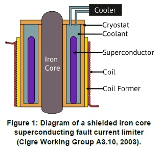
The induced current in the shorted superconducting coil balances the ampere turns of the primary winding during normal operation, ensuring a low impedance. The superconducting coil effectively shields the iron core from the primary winding because of the Meissner effect, resulting in negligible flux in the iron core. When a fault occurs, the super-conducting coil quenches to a normal phase and no longer shields the iron core, resulting in an immediate and drastic increase in network impedance that limits the fault current. This 'self-triggering', along with the non-requirement of current leads and the relatively short length of superconductor required, is one of the major advantages of this type of SFCL. The entire device is, however, characterised by its large volume and weight and is therefore not actively pursued as a viable alternative for medium voltage alternating current applications. It is being developed for use in high voltage direct current (HVDC) grids and has emerged as the most likely candidate for commercialisation and application in HVDC grids owing largely to its superior recovery characteristics and low energy dissipation (Wei et al, 2019).
1.2 The saturated iron core superconducting fault current limiter
One of the significant advantages of the saturated iron core superconducting fault current limiter is that its functionality is not dependent on superconductor quench and it therefore has a much reduced recovery time and longer operational life than other SFCLs. However, like the inductive SFCL, it has a large volume and weight, and is considered for use mainly on high voltage networks, e.g., a 300 MVA unit that was recently installed on a 220-kV network in China (Xin et al, 2012). Figure 2 is a representation of a single phase of a saturated iron core SFCL that has been adapted from Niu et al. (2014). This SFCL has two iron cores for each phase which are both excited alternating current (AC) coils (from the grid) and a superconducting direct current (DC) coil.
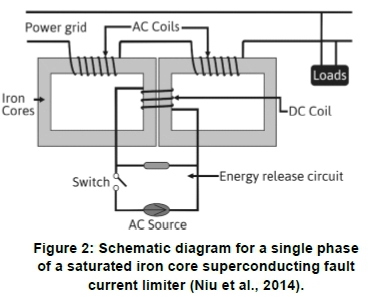
A superconducting DC coil, during normal operation, saturates the iron core and the voltage drop across the AC copper coils is nearly zero. During a fault, however, the superconducting coil is switched off, allowing the voltage drop across the two AC windings to rise sharply, thereby limiting the fault current by appearing as reactors. The most recent advancement in this technology was made in China, where a construction and testing of a 500-kV saturated iron core superconductive fault current limiter was recently completed (Liang et al., 2018). It contains the largest constructed high temperature superconductor coil to date with an inner diameter of 1 940 mm and an outer diameter of 2 040 mm. Although these devices are not yet economically feasible, the research and development attained during their construction and subsequent testing is invaluable to the superconductor field of study.
1.3 The resistive superconducting fault current limiter
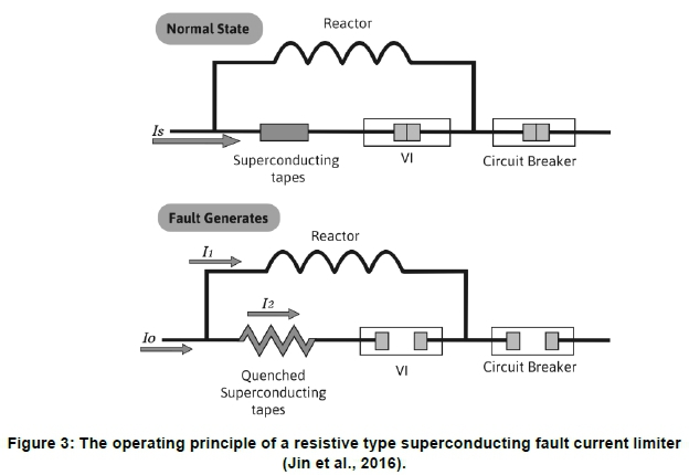
The resistive superconducting fault current limiter is the most popular SFCL configuration to solve the problem of increasing fault levels, because of its more compact size in comparison with other SFCL technologies and its applicability at 'medium-voltage' voltages (Barzegar-Bafrooei et al., 2018). During normal operation the total full load current flows through the superconducting tape and therefore presents a very small impedance to the network. When a fault occurs, the superconductor quenches rapidly and this results in an almost instantaneous inclusion of additional impedance to the network. The resistive SFCL is often installed, as shown in Figure 3, with a shunt reactor connected in parallel to it as a protective measure and to improve the service life of the device. In this example, during a fault, the fault current flows through the reactor instead, which then generates a magnetic field. This field is utilised to activate the vacuum interrupter connected in series with the superconducting tape, thereby allowing most current during a fault to flow through the shunt reactor. This ensures that the superconducting tape is only exposed to the full short circuit current for a very limited time.
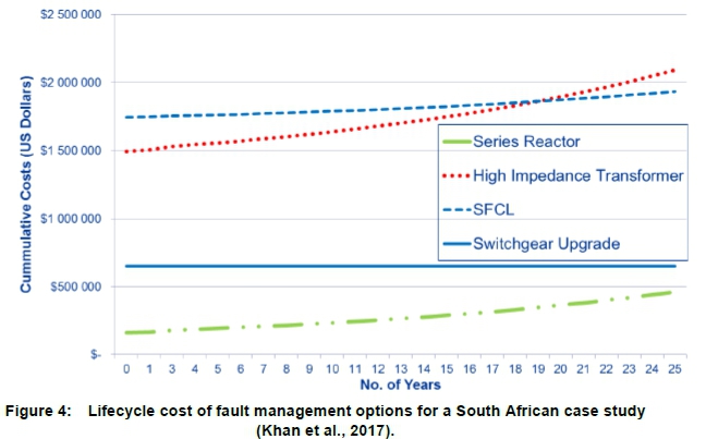
The first resistive type SFCL, CURL10, was successfully tested in 2003 for one year within the distribution grid of Rheinisch-Westfälisches Elektrizitätswerk in Germany (Noe et al., 2005). The CURL10 system then passed a further long-term test proving its reliability and safe operation at Forschungszentrum Karlsruhe, (Baden-Wurttemberg, Germany, 49°00'34"N 8°24'42"E) from 2005 to 2007. Since then, resistive SFCLs have been installed and tested at various laboratories and substations throughout the world and could be considered the most commercially mature SFCL. However, the installed cost of the SFCL, which is driven predominantly by the price of the superconducting tape utilised, remains its main impediment to viable consideration. A recently published South African case study (Khan et al, 2017) has shown that even when one considers total lifecycle costs the more energy efficient SFCL would still not be considered a viable option when compared with traditionally employed options. This case study, however, did not consider carbon tax penalties, the higher cost of electricity in some parts of the world and the available space in a substation yard. The total lifecycle costs associated with this case study are presented in Figure 4, where the initial purchase price of the resistive SFCL is shown to be the major obstacle to its financial viability. As an alternative, development of a novel superconducting series reactor (SSR) is proposed, which could potentially achieve the desired fault level reduction required, yet at a reduced lifecycle cost.
The SSR is fundamentally a superconducting coil that would be more efficient than a series air core reactor as it would have less losses attributed to Joule heating i.e. 'I2R' losses. The determination of AC power loss is important for any grid-connected device. Research that improves upon this is ongoing in new and innovative ways (Dai et al, 2014, Se et al, 2011). The cost of the SSR would be significantly less than the resistive SFCL solution because it is designed to use less superconducting tape.
1.4 Justification for a superconductor-based series reactor
This paper investigated the unique concept of making a series reactor superconducting, that is, the development of a SSR, which is essentially a series reactor that is wound with superconducting tape as opposed to copper wire. Unlike a SFCL where quenching is a functional requirement, the SSR would remain in a superconducting state during both normal and fault operation. This would be achieved by utilising enough superconducting tape to ensure that the device would not quench when exposed to a momentary rise in current during a fault. A shunt resistance across the SSR, which would be effectively shorted during normal operation, could also be utilised to further protect the device. This design philosophy would utilise less superconducting tape than a SFCL.
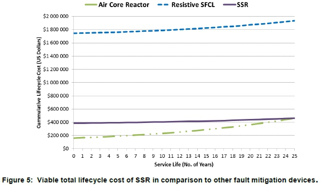
The winding of a reactor using superconducting tape that would not quench during a fault has become realisable due to the recent current density improvements of superconducting wire, as illustrated in Applied Superconductivity Centre (2018). Research into the use of parallel superconducting tapes which effectively increase the combined current carrying capability of a superconducting wire (Honda et al., 2017; Sagawa et al., 2019), has also contributed to this development. The total lifecycle costs for the series reactor and the SFCL in Figure 5 are as determined in the case study undertaken in Khan et al. (2017). The blue dashed line in Figure 5 represents the calculated lifecycle cost of a SSR needed for it to be considered a viable alternative to a series air core reactor.
It was assumed that the efficiency of the SSR was four times better than that of the series air core reactor. Using this assumption and the assumptions made in the earlier case study (Khan et al., 2017), one may determine the maximum initial investment cost of the SSR, which in this scenario would be USD 386 917. Any improvement in efficiency for the SSR would therefore result in an allowable increase in the capital investment cost of the SSR or make the SSR more financially viable.
2. Material and experimental
The cost and technical complexity of a prototype SSR necessitated the construction, initially, of a desktop prototype. This scaled prototype would confirm functionality and efficiency; and guide the design and construction of the large-scale grid connected prototype. The construction and testing of this desktop SSR has been published and has been included in this study for continuity (Khan et al., 2020).
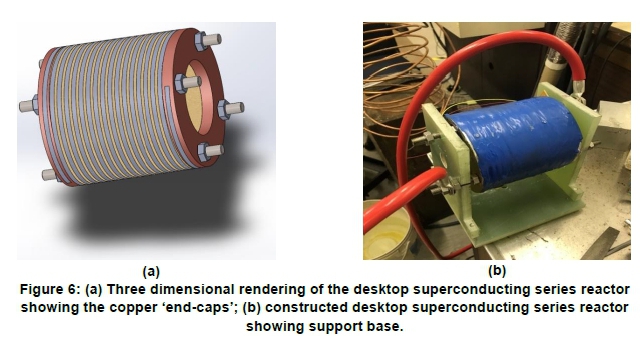
2.1 Construction of a desktop superconducting series reactor
The coil measured 110 mm and 122 mm in width and height respectively, and comprised 17 turns wound around a hollow epoxy resin former (Figure 6(a)). It was wound using a single layer of 4 mm (Re)BCO superconducting tape that had a minimum critical current of 146 A. The 10 mm high copper 'caps' were utilised to facilitate the attachment of the superconducting tape by soldering and its subsequent connection to the external experimental power circuit. Figure 6(b) shows the support structure that was built using an epoxy resin former to mount the reactor during the experiment.
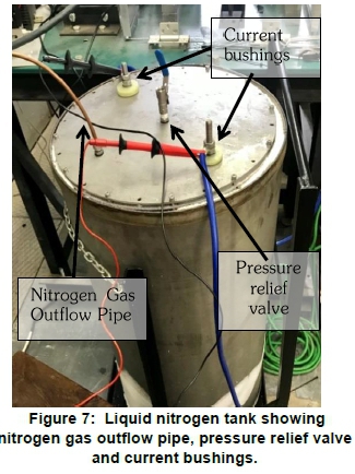
For the functionality tests, the desktop SSR was compared with a geometrically identical reactor that was wound using 3.15 mm insulated copper wire. The double-walled tank that was designed and constructed for this device was manufactured from Grade 316 stainless steel and was hermetically sealed to ensure that the liquid nitrogen did not leak through the weld seams of the tank and that the effect of the environmental power loss was reduced. Additional thermal insulation was added between the two cylinders that made up the tank to further reduce the power loss. As shown in Figure 7, the current bushings and the pressure relief valve were installed on the lid of the tank that was sealed after the liquid nitrogen was introduced into the tank.
2.2 Superconducting series reactor functionality verification
After construction, the electrical integrity of the coil and its ability to remain in a superconducting state throughout the experiments were first confirmed. The critical current of the superconducting tape utilised is 146 A and it was confirmed that the critical current criterion of 1 \x\!/cm was not exceeded up to a current of 120 A. This was the maximum current that could be supplied from the Oxford Instruments Mercury iPS DC Power supply that was used. This confirmed that the construction (winding, soldering and attachment) of the SSR was successful. To confirm that the SSR would function as intended, the following requirements were verified:
• that the fault current reduction for the SSR was equitable to that achieved with a traditional series reactor; and
• that this functionality was achieved whilst utilising less continuous operating power.
The first requirement was achieved by subjecting the SSR to a fault current and comparing the fault current reduction with that achieved with a traditional series reactor. The second requirement was achieved by comparing the resistive power loss of the SSR with the copper equivalent reactor at three different currents (15 A, 20 A and 25 A). This was reported in detail in Khan et al. (2020) and Figure 8 confirms that the desktop SSR functioned as envisaged.
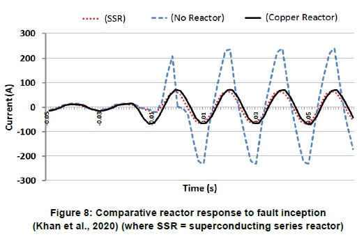
As is clearly illustrated in Figure 8, the fault current magnitude (236 A) was considerably and equivalently reduced with the introduction of either the SSR (68 A) or the copper equivalent reactor (72 A). Figure 9 also confirms that the resistance of the equivalent copper reactor was more than four times greater than that of the SSR for varying load currents. This result supported the concept that utilising a SSR would result in reduced system losses when compared to a traditional copper air core reactor.

Although the reduction of the resistive component of the inductance was considerable, this would not result in a large impedance reduction for the total device, as the impedance of a reactor is dominated by its inductance, which remains constant for both devices. However, as the reactor is a passive device and continuously connected to the network, any improvement in efficiency would have an impact on the system technical losses and by extension the operating cost of the device and its total lifecycle assessment.
2.3 Power loss measurement
As the long-term power loss would be a key factor during the trial phase of the prototype SSR, a suitable method to determine this would need to be determined. There are primarily three commonly used measurement techniques utilised when determining the AC power loss of a superconducting device or experiment : the magnetometer method, the electrical method, and the calorimetric method.
Each has distinct benefits and disadvantages and all are applicable to the full range of superconducting power applications. Selection of the appropriate method to utilise for AC power loss would depend on the size/complexity of the device and the sensitivity/accuracy required. The magnetometer method measures hysteretic loss in the presence of DC or a low sweep-rate magnetic field. It requires sensitive equipment, i.e., either a superconducting quantum interference device (SQUID) or a vibrating sample magnetometer (VSM). This method is, therefore, better suited to measure small samples or experiments conducted specifically under laboratory conditions. As the electrical method was used to determine the power loss in Figure 9, it was decided that the calorimetric power loss method would be further investigated to determine which method would be utilised during the trial phase of the prototype. The present study was interested in the total AC power loss of the SSR, as this information could be used to optimise the construction of the grid-connected SSR. It could also be used to determine the amount of liquid nitrogen required for the trial phase and the specifications for the cryocooler when required for long-term grid installation. The calorimetric method could involve either the measurement of cryogen boil-off or the temperature increase of the sample. In this experiment, the nitrogen boil-off that resulted from heating of the coil because of electric current flow in the desktop SSR was measured. The heat input of the surrounding environment was also measured.The amount of gas measured was, therefore, indicative of the total power loss of the device and not just the power loss of the coil. In Equation 1 (Okamoto et al., 2006), the AC power loss, W in watts is calculated from the gas flow rate, Q in 1/s.
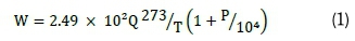
where T is the gas temperature in Kelvin and P is the differential pressure measured at the gas meter in mmH2O.
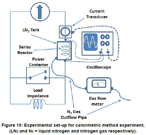
2.3.1 Experimental set-up
The experiment to confirm the suitability of the calorimetric method, involved energising the SSR to varying currents and then allowing it to first stabilise. Thereafter, the flow rate of nitrogen gas that exited the test chamber was measured using a gas flow meter and recorded. It is given that 1 Watt of dissipated power provides a gas flow rate of 258 ml/min at standard temperature and pressure (Coletta et al., 1999). Using this, the power loss of the experiment was calculated and compared with the power loss as determined electrically by computing the product of the corresponding current and voltage measured across the coil. The validity of using the calorimetric method to measure AC loss for a superconducting device was confirmed using the experimental set-up presented in Figure 10.
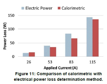
2.3.2 Results of the calorimetric method experiment
The results of this experiment are presented in Figure 11, which shows that the calorimetric method tracked the measurements obtained using the electric method. One of the requirements of the calorimetric method was for the tank to be hermetically sealed to ensure that all the gas was expelled via the gas flow meter. A drawback of this method is that it does not measure instantaneous surges very accurately. The use of the calorimetric method of power loss determination would be favoured for the prototype SSR as it has been shown to be effective in determining the total AC power loss, it does not impose a limitation on the shape and size of the coil, and it is insensitive to electromagnetic noise.
One identified modification for the construction of the prototype SSR is that a secondary chamber, which is open at the bottom, be installed over the superconducting coil inside the cryogenic tank. This would allow for an increase in measurement sensitivity as the nitrogen bubbles around the coil would be locally contained.
3. Prototype SSR design
The functionality of the SSR has been confirmed with the construction and testing of the desktop SSR. The prototype was designed for application on a 22-kV medium voltage distribution network, as it is common practice to build both 11-kV and 22-kV medium voltage networks to a 22-kV equipment standard. This facilitates voltage upgrade projects that may be required in the future.
3.1 Determining the superconducting series reactor inductance
When the desired fault current is known, the reactance required for a current limiting reactor is given in (2).
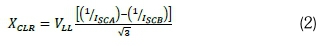
where Isca and Iscb represent the desired and existing short circuit current values (kA) respectively and Vll represents the system voltage in kV. In a typical 22-kV distribution substation, the equipment is rated to a maximum of 25 kA . It is therefore necessary to reduce the fault level to be significantly below 25 kA to remain within equipment specifications to reduce transformer inrush current (Seo et al, 2010) and/or improve a network voltage imbalance (Huh et al, 2013). Hence, it was decided that a reactor would be designed to correspond with a fault level reduction from 25 kA to 10 kA on a 22-kV network. To achieve this reduction using Equation 2, it was determined that a coil with an inductance of 2.43 mH would be required.
3.2 Superconductor coil design
The main motivation for the design of SSR is to reduce the capital cost of a superconducting fault management device by utilising significantly less superconducting tape than the quantity used in a SFCL. Recent designs of resistive based SFCLs have reported using 1.65 km and 1.88 km (Schmidt et al, 2008; Martini et al, 2012) of superconducting tape respectively in their construction. During a fault, the superconducting element of the superconducting tape in a resistive SFCL quenches and the voltage is distributed across the substrate of the superconducting tape. The amount of superconducting tape required is therefore calculated to ensure that the substrate can dissipate the energy created by the fault without catastrophically failing. The SSR has been designed to be wound with three 12 mm wide (RE)BCO-based 2G high temperature superconductor tapes connected in parallel. This is the widest commercially available superconducting tape and has a rated minimum critical current of 360 A (self-field). This configuration would ensure that the SSR is rated to carry the normal load current and the expected fault current at the initially proposed test site.
Both the design of a thin walled solenoid and the design of a pancake coil were considered to achieve the desired reactance to reduce the fault level. The general dimensions given in Iwasa (2009) for a superconducting coil may be used to determine the inductance of various superconducting coil designs. The major parameters defining a coil containing no ferromagnetic materials are the internal diameter (a1), the outer diameter (a2), the height (2b) and the number of turns (N). The self-inductance for the coil, L, may be determined by Equation 3, where a = a2/a1and ß = b/a1. These parameters are dimension-less and serve to describe the shape of the coil. The self-inductance for a pancake coil (a»1) may be approximated using Equation 4.
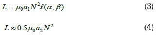
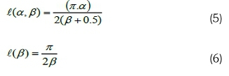
For a solenoid, where ß->1, the inductance parameter, l(a,ß), required in Equation 2 is determined by Equation 5, and the inductance parameter l(ß), for a thin walled long solenoid (a ~1 and ß=>oo) reduces to Equation 6.
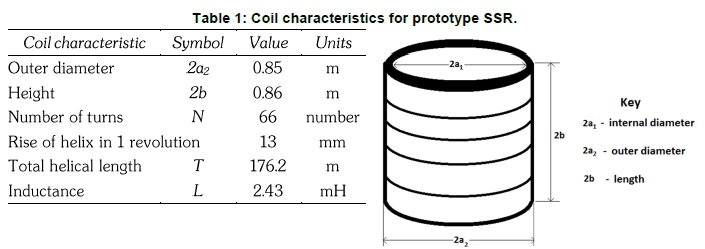
The total helical length of superconducting tape used in the construction of the reactor was one of the main parameters considered for the design of the coil. Other parameters considered were the overall tank dimensions, the medium voltage bushing spacing and the basic insulation level for substation equipment installed on the South African power grid. For the configurations considered, the thin-walled solenoid and pancake coil yielded a maximum inductance per unit length of 13.77 μH/m and 3.64 μH/m respectively. It was therefore decided that a thin-walled solenoid would be used in the prototype SSR. The characteristics of the prototype SSR are given in Table 1 and were determined using the generalized reduced gradient nonlinear optimisation algorithm. The algorithm was configured to optimise the length of superconducting tape for the required inductance. The design of the prototype SSR would require a total of approximately 530 m of superconducting tape. This would be a significant reduction from the length typically required for resistive SFCLs installed on medium voltage networks, i.e. 1.65 km and 1.88 km respectively (Schmidt et al., 2008; Martini et al., 2012).
The coil for the prototype was designed using a single layer of superconducting tape, as this would be less complex to construct than a coil with multiple layers, and was adequate for this stage of the development. A Brook's coil with an inductance of 2.43 mH and an internal diameter of 0.2 m would theoretically yield an inductance per unit length of 39.63 μH/m, which represented a more optimum solution with regards to inductance per unit length , but this comes with significant complexity during construction. There would be scope for further reduction of the physical footprint of the SSR in future developments of the device if the use of multiple layers of windings is considered. This is further encouraged when one takes in account the relatively small bending radius of the superconducting tape when compared to copper conductors.
The coil has been designed to be wound in a single layer on a hollow former manufactured from G10 epoxy resin, which is an industrial laminate composed of a continuous filament glass cloth material with an epoxy resin binder. The coil would then be encapsulated with an epoxy resin which is thermally conductive and electrically insulative. The technical parameters for the SSR would be similar to those determined for traditional current limiting reactors as specified in IEC 60076-6:2007.
3.3 Tank dimensions for prototype superconducting series reactor
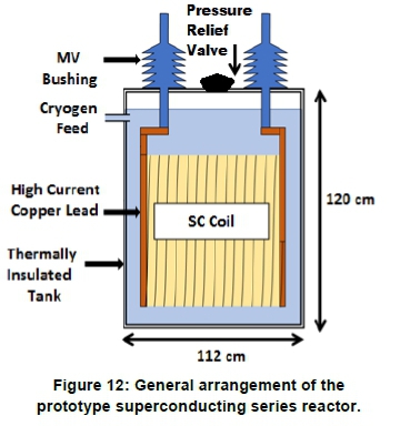
The tank that houses the SSR would be manufactured from a high chromium-containing corrosion resistant stainless steel (316SS). The dimensions of the tank would be determined by the insulation thickness, the coil dimensions and the dielectric breakdown strength of air and liquid nitrogen. A BIL of 150 kV (Um) was used, however a safety factor (SF) of 2 was also incorporated as this is a prototype device and optimization of the tank size was not a consideration at this stage of the development. Not taking into account the small layer of air between the top of the tank and the level of liquid nitrogen, the equations used to dimension the tank are provided in Equations 7(a) and 7(b).
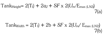
The superconducting coil would be positioned on its horizontal axis, hence the coil diameter (2a2) and height (2b) have been transposed in the equations to determine the tank height and width. A value of 3 kV/mm was used as the AC breakdown voltage of air, (Emax(air)). The liquid nitrogen in the tank is used to not only cool the superconducting coil but also to provide electrical insulation. This is, however, influenced by pressure and the presence of nitrogen gas bubbles. Based on research in Fink et al. (2014), the AC breakdown voltage of liquid nitrogen (Emax(LN2)) was conservatively estimated at 10 kV/mm for the design of the SSR tank. 'Ti' represents the insulation thickness of the vacuum jacket in equations 7(a) and 7(b). The dimensions of the tank were, therefore, calculated as having a width of 112 cm and a height of 120 cm. The vertical bushings required to connect the system voltage to the coil housed within the tank would conform to International Electrotechnical Commission (2008) by having a creepage of 31 mm/kV, as the research site has been classified as a high pollution area on account of its proximity to the ocean. The tank would also be instrumented with a range of sensors to measure the temperature and current at critical locations and voltage taps. Figure 12 shows the proposed general arrangement of the prototype SSR.
3.4 Cost of the prototype superconducting series reactor
The material cost for the prototype SSR has been estimated to be approximately USD 120 000 per phase. The major contributor to that cost (approximately 65%) was for the superconducting tape that is required for the superconducting coil. Other significant costs included the vacuum jacket within the tank to reduce heat loss from within the device and the G10 epoxy resin which would be used as a former for the coil. Figure 5 determined the maximum allowable capital investment cost for an SSR that is four times as energy-efficient as a traditional air core reactor to be USD 386 917, and this compares well to the estimated cost of the prototype SSR.
4. Installation at a grid-connected research site
4.1 Overview ofDoornkop research test site
The purpose of the Eskom Doornkop research test site, shown in Figure 13, is to test various public safety-related protection and detection measures, including the detection of high impedance faults caused by downed conductors and the fast detection and clearance of human and animal contact with low-hanging conductors.
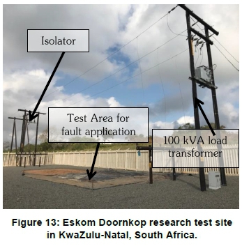
This test site was commissioned in 2016 and is energised via an Eskom 22-kV distribution network (Doornkop NB10) in KwaZulu-Natal, South Africa. With a few minor design modifications one would be able to also utilise the existing research site to test the prototype SSR. This would allow for the testing of the device in a realistic and representative environment and to also allow for long term studies into key critical aspects such as electric power loss and cryogenic performance. The total cost of this modification is approximately USD 4 000 and is primarily for the installation of an additional isolator to allow the SSR to be bypassed, when required. The site is also equipped with control and measurement equipment to allow for remote monitoring and control.
4.2 Advantages for initial prototype testing at Doornkop research test site
The real advantage for evaluating the superconducting series reactor at the Doornkop test site is the ability to control the application and magnitude of network faults. The capability to control every aspect of the fault (phase, multiple phase, fault current and fault duration) is a substantial benefit over testing the device in the actual grid, where faults are uncontrolled and occur incidentally. At Doornkop, faults can be initiated when required and this would have no impact on existing customers. The magnitude of the fault level at the research site is flexible and may be varied by controlling the fault impedance in the test area where the conductor/s is grounded to simulate a fault. This is beneficial if one considers the fluctuating fault level contribution from the rotating machines associated with distributed generation installations (Berry et al, 2013).
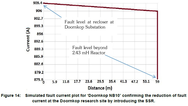
The fault level at the research site is comparatively low (0.9 kA) when compared to the fault levels at traditional urban distribution substations. Therefore, the reduction in fault level at Doornkop research site after installing a 2.43 mH reactor is comparatively small. Although small, this reduction in short circuit current will be measured without difficulty as the research site is equipped to measure current to within a resolution of 10 mA. Reticmaster® is an electrical power analysis software design tool. It was used to verify the reduction of fault current at the Doornkop research site when the 2.43 mH reactor is installed. The results from Reticmaster® are presented in Figure 14 and indicates a fault reduction of 30 A.
This is clearly not the ideal site to test the fault reduction capability of the SSR, but the use of a series reactor to reduce fault levels is a well-established technology . The installation of this novel prototype superconducting power device at this site allows for further investigation into the operating power loss (both thermal and electrical), the effect of auto reclose cycles on the superconductor, and the quench dynamics and behaviour when multiple superconducting tapes are connected in parallel. After this initial phase of research and testing is complete, it is envisaged that the SSR would be subjected to the applicable type tests at a high voltage test laboratory. These tests would be similar to those used in the specification for traditional air core reactors . After successfully completing these tests, the SSR would be installed at a location on the network that has a high fault level, for a long-term pilot study.
5. Conclusion
This paper has investigated the novel alternative of a superconducting series reactor (SSR) in the management of distribution fault levels, essentially as an equivalent for a traditional air core reactor. The advantage of the SSR over the air core reactor is that it would be more energy efficient, carbon emission friendly and designed to potentially occupy a smaller footprint in the substation yard. The first phase of this development was the construction and testing of a desktop SSR. Earlier experiments confirmed the functionality of the desktop SSR, with regards to fault current reduction and power efficiency (Khan et al, 2020). The calorimetric method of power loss determination was investigated in this paper and found to be comparable with results obtained using the electrical method.
Design parameters for a prototype SSR that would reduce the fault current on a 22-kV network from 25 kA to 10 kA were determined. These were then used to calculate the material cost of the prototype SSR. Due to a reduction in the length of superconducting tape required, the cost of the SSR was significantly lower than that of a resistive superconducting fault current limiter. The SSR cost was also below the maximum initial investment cost required to make it financially viable as a fault current mitigation device. It was also proposed that the prototype SSR undergo its initial phase of testing at the Doornkop research test site. This is an established grid-connected research site that would allow total control of fault current application, with no impact on customers.
Some of the future concepts still to be explored are the space reduction achievable with the SSR in a substation yard when evaluating various methods of fault level reduction, and the construction of the superconducting coil using modular components, thereby facilitating maintenance and scalability.
The modification of the existing Doornkop research site so that it could be used for applied superconductivity research is a significant milestone in the effort to adopt superconducting power devices on the grid. Although this paper focuses on the novel development of the SSR concept, the required modifications could just as easily be used to evaluate other superconducting power devices.
Acknowledgment
The authors thank the Eskom Power Plant Engineering Institute for its support, and the staff at Eskom and the University of KwaZulu-Natal who assisted during the compilation of this study.
Author roles
Mohamed F. Khan is the primary author, and responsible for the simulations and experiments reported.
L. Leigh Jarvis, as PhD supervisor, significantly assisted in research formulation, equipment construction and experimental technique, and with the paper's structure.
Edward A. Young assisted on the design of the prototype and with good laboratory practices as well as research formulation and review of the paper. Andrew G. Swanson helped to run the experiments and capture data from them, and contributed to editing and revision.
Jonathan C. Archer assisted with the prototype design and when working with equipment in the Materials Science laboratory, as well as with editing the paper.
Robert G. Stephen is the industrial mentor for the primary author as part of the EPPEI programme. He assisted with the research formulation, monitoring of project milestones and deliverables, and in reviewing the paper.
ORCiDs: Khan: https://orcid.org/0000-0003-1395-8608 Leigh Jarvis: https://orcid.org/0000-0002-5125-7530 Young: https://orcid.org/0000-0002-0917-5371 Swanson: https://orcid.org/0000-0002-9965-4746 Archer: https://orcid.org/0000-0002-2944-7848 Stephen: https://orcid.org/0000-0002-8157-1221
References
Applied Superconductivity Centre, 2018. The expanded ASC'Plots'page. [Online] Available at: https://fs.magnet.fsu.edu/~lee/plot/plot.htm [Accessed 08 02 2020]. [ Links ]
Barzegar-Bafrooei, M. R, Foroud, A. A, Ashkezari, J. D. & Niasati, M, 2018. On the advance of SFCL: a comprehensive review. IET Generation, Transmission and Distribution, 13(17): 3745 - 3759. [ Links ]
Berry, J, Jupe, S, Meisinger, M, & Outram, J. (2013). Implementation of an active fault level monitoring system for distributed generation integration. 22nd International Conference on Electricity Distribution. Stockholm: 0619 [ Links ]
CIGRE WG D1.38. (2015). Common Characteristics and Emerging Test Techniques for High Temperature Superconducting Power Equipment. Paris: Cigre. [ Links ]
Cigre Working Group A3.10. (2003). Technical Brochure 239: Fault Current Limiters in Electrical Medium and High Voltage Systems. Paris: Cigre. [ Links ]
Coletta, G, Gherardi, L, Gomory, F, Cereda, E, Ottoboni, V, Daney, D, Maley, M, Zannella, S. (1999). Application of electrical and calorimetric methods to the AC loss characterization of cable conductors. IEEE Transactions on Applied Superconductivity, 9(2): 1053-1056. [ Links ]
Dai, J. S, Wang, Y. S, Zhao, W. J, Xia, L. M, & Sun, D. (2014). A novel calorimetric method for measurement of AC losses of HTS tapes by optical fiber bragg grating. IEEE Transactions on Applied Superconductivity, 24(5): 9002104. [ Links ]
Fink, S, Kim, H. R, Mueller, R, Noe, M, & Zwecker, V. (2014). AC breakdown voltage of liquid nitrogen depending on gas bubbles and pressure. 2014 International Conference on High Voltage Engineering and Applications (ICHVE). Poznan: 14917794 [ Links ]
Harlow, J. H. (2012). Electric power transformer engineering. Boca Raton: CRC Press. [ Links ]
Honda, S, Iwakuma, M, Fukumoto, Y, Yoshida, K, Sato, S, Izumi, T, Tomioka, Akira. (2017). Current-sharing properties in parallel conductors composed of REBCO superconducting tapes. IEEE Transactions on Applied Superconductivity, 27(4). 0601405. [ Links ]
Huh, J.-S., Shin, H, Moon, W., Kang, B., & Kim, J. (2013). Study on voltage unbalance improvement using SFCL in power feed network with electric railway system. IEEE Transactions on Applied Superconductivity, 23(3): 3601004. [ Links ]
International Electrotechnical Commission. (2007). IEC 60076-6: Power transformers - Part 6: Reactors. Geneva: IEC. [ Links ]
International Electrotechnical Commission. (2008). IEC 60137 - Insulated bushings for alternating voltages above 1000 V. Geneva: IEC. [ Links ]
Ireson, G. (2012). Discovering superconductivity: An investigative approach. Nottingham: Wiley. [ Links ]
Iwasa, Y. (2009). Case studies in superconducting magnets: design and operatinal Issues. New York: Springer Science + Business Media. [ Links ]
Jin, J. X, Tang, Y. J, Xiao, X. Y, Du, B. X, Wang, Q. L, Wang, J. H, Wang, S.H., Bi, Y.F., Zhu, J. (2016). HTS power devices and system: principles, characteristics, performance and efficiency. IEEE Transactions on Applied Superconductivity, 26(7): 38000526. [ Links ]
Khan, M. F, Jarvis, A. L, Swanson, A. G, Stephen, R. G, Young, E. A, & Archer, J. C. (2020). Design, construction and testing of a desktop superconducting series reactor towards MV grid application. IEEE Transactions on Applied Superconductivity, 30(5): 5601306. [ Links ]
Khan, M. F., Jarvis, L., Young, E. A., & Stephen, R. G. (2017). A technical and economic comparison between traditionally employed and emerging fault level management solutions at distribution voltages. Africa Research Journal, 108(1): 31 -38. [ Links ]
Kim, M. J, Lee, G.-H, Bang, S.-H, Park, H. Y, Choe, W, Sim, J, Lee, S.W., Kim, Y.G, Kim, H.R. (2011). The application of a fault current limiter at Icheon substation in Korea. 1st International Conference on Electric Power Equipment - Switching Technology. Xi'an: 362-365 [ Links ]
Klaus, D., Waller, C, Jones, D., McWilliam, J., Berry, J., Bock, J., Helm, J., Jafarnia, M., Hobl, A. (2013). Superconducting fault curent limiters - UK network trials live and limiting. 22nd Int. Conf. Exhibition on Electricity Distribution (CIRED 2013), Stockholm, Sweden: 1-4 [ Links ]
Lee, B. W., Sim, J., Park, K. B., & Oh, I. S. (2008). Practical application issues of superconducting fault current limiters for electric power systems. IEEE Transactions on Applied Superconductivity, 18(2): 620-623. [ Links ]
Liang, C, Li, G, Zhang, P., Song, M., Ma, T., Zhou, T., Ge, Z. (2018). Winding technology and experimental study on 500kV superconductive fault current limiter. IEEE Transactions on Applied Superconductivity, 28(3): 5601105. [ Links ]
Martini, L., Bocchi, M., Ascade, M., Valzasina, A., Rossi, V., Angeli, G, Ravetta, C. (2012). Development, testing and installation of a superconducting fault current limiter for medium voltage distribution networks. Physics Procedia, 36: 914 - 920. [ Links ]
McLaren, B. (2016). Medium Voltage Reticulation Standard: Section 0. Sunninghill: Eskom Holdings Pty Ltd. [ Links ]
Murgatroyd, P. N. (1986). The Brooks inductor: a study of optimal solenoid cross sections. IEE Proceedings, 133, Pt. B(5): 309 - 314. [ Links ]
Mushwana, C. (2016). Short circuit current management standard (Doc Number: 240 - 83559364). Sunninghill: Eskom Holdings. [ Links ]
Niu, X., Chen, Z., Wang, H, Chen, Z., Zhang, L, Niu, G, Hong, H, Xin, Y. (2014). Structure and performance characteristics of saturated iron core superconducting fault current limiter. Journal of International Council on Electrical Engineering, 4(2): 146-150. [ Links ]
Noe, M., Hobl, A., Tixador, P., Martini, L, & Dutoit, B. (2012). Conceptual design of a 24 kV, 1 kA resistive superconducting fault current limiter. IEEE Transactions on Applied Superconductivity, 22(3): 5600304. [ Links ]
Noe, M., Juengst, K.-P., Elschner, S., Bock, J., Breur, F., Kreutz, R., Kleimaier, M., Weck, K-H, Hayakawa, N. (2005). High voltage design, requirements and tests of a 10 MVA superconducting fault current limiter. IEEE Transactions on Applied Superconductivity, 15(2): 2082-2085. [ Links ]
Okamoto, H, Sumiyoshi, F., Miyoshi, K, & Suzuki, Y. (2006). The nitrogen boil-Off method for measuring AC losses in HTS coils. IEEE Transactions on Applied Superconductivity, 16(2): 105-107. [ Links ]
Oxford Instrumements, 2020. Oxford Instruments Nanoscience. [Online] Available at: https://nanoscience.oxinst.com/products/control-electronics/mercuryips#product-information-tabs [Accessed 28 May 2020]. [ Links ]
Prigmore, J. R., Mendoza, J. A., & Karady, G. G. (2013). Comparison of four different types of ferromagnetic materials for fault current limiter applications. IEEE Transactions on Power Delivery, 28(3): 1491-1498. [ Links ]
Roux, A. 1. (2011). Network Technology Plan for Distribution - Doc. Number 240 41793930. Sunninghill: Eskom Holdings. [ Links ]
Ryan, H. M. (2013). High- voltage engineering and testing. London: The Institution of Engineering and Technology. [ Links ]
Sagawa, S, Miura, S, Iwakuma, M, Fukumoto, Y, Yoshida, K, Sato, S, Izumi, T. (2019). Theorethical investigation of current-sharing properties of three-strand parallel conductors composed of REBa2Cu30y superconducting tapes. IEEE Transactions on Applied Superconductivity, 29(5): 4800605. [ Links ]
Schmidt, W, Kraemer, H. P, Neumeller, H. W, Schmitt, H, Malozemoff, A. P, & Otto, A. (2008). Limiting short circuit currents in electrical networks with superconductor wires. Cigre'Conference 2008, Paris: Dl-102 [ Links ]
See, K. W, Cook, C. D, & Dou, S. X. (2011). Innovative calorimetric AC loss measurement of HTSC for power applications. IEEE Transactions on Applied Superconductivity, 21(3): 3261-3264. [ Links ]
Seo, H.-C, Kim, C, Rhee, S, Kim, J, & Hyun, O. (2010). Superconducting fault current limiter application for reduction of the transformer inrush current: A decision scheme of the optimal insertion resistance. IEEE Transaction on Applied Superconductivity, 20(4): 2255 - 2264. [ Links ]
Wei, Z, Xin, Y, Yang, C, Lan, J, & Li, Q. (2019). A new type of C superconducting fault current Limiter. IEEE Transactions on Applied Superconductivity, 29(5): 5602905. [ Links ]
Xin, Y, Gong, W. Z, Sun, Y. W, Cui, J. B, Hong, H, Niu, X. Y, Wang, H.Z., Li, Q, Zhang, J.Y., Wei, Z.Q, Liu, L, Yang, H, Zhu, X.H. (2012). Factory and field tests of a 220 kv/ 300 MVA saturated iron-core superconducting fault current limiter. IEEE Transactions on Applied Superconductivity, 23(3): 5602305. [ Links ]
* Corresponding author: Tel.:+27 (0)83 556 0503; email: KhanMa@eskom.co.za

