


Services on Demand
Article
 English (pdf)
 Article in xml format
 Article references
Indicators

Related links
-
 Cited by Google
 -
 Similars in Google
Share

 Permalink
Journal of Energy in Southern Africa
On-line version ISSN 2413-3051
Print version ISSN 1021-447X
J. energy South. Afr. vol.31 n.1 Cape Town Feb. 2020
http://dx.doi.org/10.17159/2413-3051/2020/v31i1a7430
ARTICLES
Small signal stability analysis of a four-machine system with placement of multi-terminal high voltage direct current link
Oluwafemi E. OniI, *; Andrew G. SwansonII; Rudiren Pillay CarpanenIII
IDiscipline of Electrical, Electronic and Computer Engineering, University of KwaZulu-Natal, Durban 4041, South Africa; https://orcid.org/0000-0001-9260-0748
IIDiscipline of Electrical, Electronic and Computer Engineering, University of KwaZulu-Natal, Durban 4041, South Africa; https://orcid.org/0000-0002-9965-4746
IIIDiscipline of Electrical, Electronic and Computer Engineering, University of KwaZulu-Natal, Durban 4041, South Africa; https://orcid.org/0000-0003-1107-7057
ABSTRACT
Inter-area oscillation caused by weak interconnected lines or low generator inertia is a critical problem facing power systems. This study investigated the performance analysis of a multi-terminal high voltage direct current (MTDC) on the damping of inter-area oscillations of a modified two-area four-machine network. Two case studies were considered, utilising scenario 1: a double alternating current (AC) circuit in linking Bus_10 and Bus_11; and scenario 2: a three-terminal line commutated converter high voltage direct current system in linking Bus_6 and Bus_11 into Bus_9. It was found that scenario 2 utilising MTDC link with a robust controller provided quick support in minimising the network oscillations following a fault on the system. The MTDC converter controllers' setup offered sufficient support for the inertia of the AC system, thus providing efficient damping of the inter-area oscillation of the system.
Keywords: multiterminal direct current, MTDC link, inter-area oscillation, generator inertia, thyristors converter, high voltage direct current, converter controller
1. Introduction
The high increment in the installed capacity of synchronous machines over the recent decade has compounded the inter-area oscillation stability problem[1-3]. Inter-area oscillations usually occur when a group of generators on one area swing against another group of generators on the other side, caused mainly by weakly interconnected tie-lines between the group of generators [4]. A radially connected system that gets upgraded to form a complex and more advanced system with a very long transmission distance, resulting in lower generator inertias, has an increased inter-area oscillation problem [5]. A market-driven economy with high transmission system loading further shifts the power grid to its stability limits, to increase profits as well as to meet consumer demands, complicating the problem of small-signal stability [6, 7]. Power utilities are becoming aware of the crucial impact of small-signal stability performance of large interconnected power systems, as it contributes to the problems they frequently experience [6, 8]. Siemens stated that most power systems had been faced with inadequately damped low-frequency range of 0.2-0.8 Hz inter-area oscillations because of increasing transmission network growth and unplanned grid expansion [9].
Damping of inter-area oscillations requires extra energy to be added or expanded into or from a perturbed system, leading to an instant reduction or increase of the system oscillation of multitermi-nal direct current (MTDC) links. Based on the operating state of the system, the energy required to damp the system adequately depends on the correct phase shift settings relative to the instant systems' condition, as incorrect phase angles can excite the power system further from the steady-state operating point. It was found that, with a damping ratio of -5%, a system would be able to adequately damp almost 32% of its initial oscillation amplitude in three oscillation periods. Each power system has a different operating point, and therefore requires a different acceptable level of damping energy to reduce the whole system-oscillations' amplitudes during a fault. The smallest adequate level of damping is not known, as it depends on the system that considers their operating point, but a damping ratio that is negative causes the mode to become unstable [10-12].
Some researchers have addressed small signal stability problems relating to the generator frequency response of the power grid during a system disturbance or the normal operating condition [5, 13-19]. Elizondo et al. [13] provided a comprehensive research survey on the inter-area oscillation damping control using high voltage direct current (HVDC) or MTDC system. The approach covered a range of converter control, with active direct current (DC) power modulation in proportion to the change in the frequency of the two areas involve being an example. Li et al. [14] made use of a robust controller for a flexible alternating current (AC) transmission system devices to provide better compensation to the AC system. Elizondo et al. [13] also emphasised the importance of data-capturing of an extensive power system using phasor measurement units (PMUs) and wide-area monitoring systems to HVDC system monitoring and control. A mathematical approach of a single-machine infinite bus system and the power system stability was introduced by Kundur [15] and further analysis made by Oni et al. [17], with the emphasis limited to a point-to-point HVDC. Azad et al. [16] used supplementary predictive control in a line-commutated converter (LCC) HVDC link to enhance the small-signal stability of the same Kundur [15] network. Idowu [18] implemented an algorithm that maximally generates a damping and inertia coefficient for a virtual synchronous machine to participate efficiently in the inertia response of frequency control. Eftekharnejad et al. [19] found that high penetration of photovoltaic (PV) systems has a detrimental impact on small-signal stability of the power system, because of reduced system inertia. Therefore, Wandhare and Agarwal [20] proposed a new control scheme that enables a centralised PV-grid system to damp the low-frequency power swings on the local area network as an ancillary activity. The impact of system disturbance such as generator losses or load shedding on the system frequency was discussed in Zou (2018) [21], where the power system frequency regulation with consideration to the load-damping characteristic was analysed. Sa-ghafi [22] presented a small integrated series compensator in damping power oscillations in standalone micro-grids. Little attention was given to the small-signal analysis of two-area four-machine (TAFM) networks when interconnected with an LCC-MTDC link. The literature is mostly based on a point-to-point HVDC link as an inter-area power transfer link rather than on a comprehensive comparative analysis on MTDC operation during AC disturbance [15, 17, 23].
The present study, therefore, contributed to the performance and reduction analysis of inter-area oscillations of the modified Kundur TAFM networks by comparing the damping rate of the network oscillations when interconnected with an MTDC link, unlike the use of a double AC line. The study also evaluated the impact of modulating MTDC power flow on the AC network inter-area oscillation damping. A swing equation of incoherent two-area machines was firstly presented and analysed. Two operational scenarios were considered, and a dynamic simulation study was carried out on the system during a small-signal perturbation on two of the selected network elements to determine the damping amplitude of the generator oscillations when the MTDC model was connected on the network.
2. Methodology
A scenario was considered, covering a three-phase short circuit fault (TFSC) on the transmission line (L7_8) linking Bus_7 and Bus_8 with a fault clearing time tc=0.13s, as well as a 1.0s disturbance on the generator (Gen_4). Both faults occurred at 2.0s simulation time, i.e., a situation where both disturbances occurred simultaneously in two different areas of the study system. These cases of system disturbances were chosen to give the worst-case scenario of power system operation, which also stipulates a situation where the synchronous generator is delivering half its rated power following a TFSC fault. The same fault impedance and duration were also applied to the studied system when interconnected with the MTDC link (during the second scenario). This was to determine the performance of the MTDC transmission schemes on the small-signal stability of an electric power system. During this study, the following two scenarios were analysed:
Scenario 1: This involved using double transmission lines to link Bus_10 and Bus_11 with each line rated at 350 MVA.
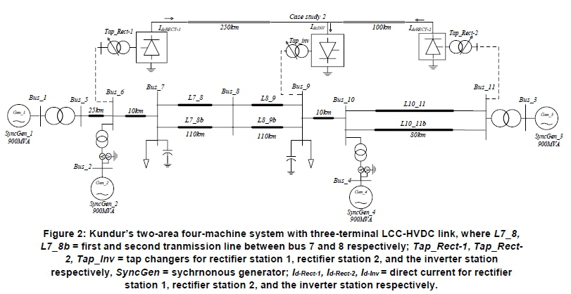
Scenario 2: The MTDC (two rectifiers and one inverter) system was used as a replacement for the AC transmission line (i.e. single AC circuit with DC line). For the AC lines L7-8 (linking Bus_7 to Bus_8), and line L8-9 (linking Bus_8 to Bus_9), a 300 MW rated rectifier (Rect-1) delivering 200 MW power was connected at Bus_6. Also, a 1000 MW rated rectifier (Rect-2) station was connected at Bus_11 to deliver 700 MW power in replacement of the transmission line L10-11b (linking Bus_10 and Bus_11).
2.1 Background theory
The inertia swings of the synchronous machine are first analysed to give the damping coefficient required to suppress the power system oscillation maximally, thereby providing a sufficient torque in controlling the system frequency. Figure 1 shows a simple schematic two-area network comprising two incoherent machines with generator inertias of H1 and H2, while δ1 and δ2represent the respective Area-1 (A1) and Area-2 (A2) rotor angle oscillating at two different frequency and amplitude.

Equations 1 and 2 give the swing for each of the machines. When they are subtracted from each other, they give Equations 3 and 4 when divided by the coefficients of inertia just before the second derivative. Simplifying Equation 4 gives Equation 5.
Avoiding the complexity of the swing equations for many coherent machines during stability analysis of a large system requires the combination of all the swing equations to decrease the number of swing equations [21]. Adding the rotating inertia H for each generator unit gives the overall system equivalent rotating inertia.

where H is the generator inertia, 5 is the rotor angle for the generator, Pm is the mechanical power, and Pe is the electrical power. The subscripts 1 and 2 stand for areas 1 and 2 respectively.
The respective equivalent inertia constant H12 and the change in rotor angle δ12between the two generators are further defined and given by Equations 6 and 7.

The Pm12 and Pe12 given by Equations 8 and 9 are, respectively, the mechanical and electrical power between the two generators.

After solving the second-order differential of Equation 5, the equivalent swing behaviour of the synchronous machine with the damping constant Kd is given by Equation 10. Equation 11 gives the undamped natural frequency (wn) in the system, while Equation 12 represents the damping coefficient Z needed to suppress the oscillation amplitude entirely.
The overall system oscillation frequency and the inertia constant are inversely proportional, implying that a system with high inertia constant is immune to a fault and vice versa. This shows that the system inertia constant is directly affected by the output generated power. Therefore, for a more stable operating point of a power system, it requires inertia constant >3.5 pu.

where wn is the undamped natural frequency, ζ is the damping coefficient, Kd is the damping constant, Pmax is the maximum active power generated, w is the angular speed, and δ is the generator rotor angle.
2.2 System model
The system considered in this study is a modified version of Kundur's TAFM network, as shown in Figure 2. The transmission line interconnecting Bus_10 to Bus_11 was modified from 25 km to an 80 km, leading to high impedance on the AC transmission line. The double transmission circuits were then used to allow more power transfer and the inter-area oscillations of the entire generator during a system disturbance were then analysed using a time-domain simulation. The dynamic simulation was carried out, and the generators' power output, oscillation speed, field voltage, and inter-area power transfer were analysed.
2.3 Synchronous generator model
The synchronous machines used were modelled on power system computer-aided design (PSCAD) software using the Institute of Electrical and Electronics Engineers controller model for the automatic voltage regulator (AVR) as well as the power system stabiliser (PSS), as shown in Figure 3. All generators were rated for a realistic inertial time constant and were connected via a 20/230 kV 900 MVA transformer. The governor control of these machines was assumed constant during the investigation period to get a holistic effect of the PSS, AVR and the DC controller impacts in minimising the fault on the entire network. Modelling details of these machine controllers are fully explained in Kundur et al. [15].
2.4 Load model
The loads were modelled to have a constant current and constant impedance characteristics for its active and reactive power components respectively. Equation 13 gives the load flow and dynamic calculation of the loads.
where Q is the equivalent reactive power, P is the real power, Po is the rated real power/phase, Qois the rated reactive power (+inductive) per phase, U is the load root mean square (RMS) voltage and Uo is the rated line-to-earth RMS voltage; dP/dV and dP/dF are the voltage index and frequency index for real power respectively, while dQ/dV and dQ/dF are the voltage index and frequency index for the reactive power respectively.
2.5 Multiterminal direct current model
The multiterminal direct current (MTDC) network used is a three-terminal (two rectifiers and one inverter station) as shown in Figure 2, with parameters given in the supplementary information file.1 Equations 14 and 15 give the model voltage of the three-terminal system.

where VdR and Vdi are the rectifier and inverter direct current voltage, aR and ai are the rectifier and inverter firing angle, VtR and Vti are the rectifier and inverter alternating current terminal voltage, yr and yi are the rectifier and inverter extinction angle, Xc is the commutation reactance, and Id is the direct current voltage.
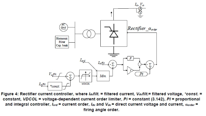
Rectifier station one (Rect-1) and rectifier station two (Rect-2) transmit power from Bus_6 and Bus_11 respectively to the inverter station (Bus_9), replacing some transmission lines (L7_8b, L8_9b, L10_11b) in the network. Fault susceptibility of the MTDC system depends solely on its overall converter controller coordination; therefore, each converter controller was pre-set and corrected to suit the study case scenarios. The current controller in Figure 4 outputs the firing angle order after calculating the difference among the filtered direct current (Idc) measured and the reference current order (Iorder), and the current error is fed into a proportional and integral (Pi) controller.
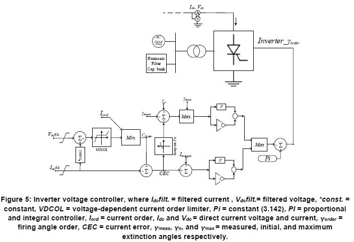
The rectifiers operate as a current controller, while the inverter, because of the minimum value selector, uses the gamma controller. The extinction angle (y) (or voltage) controller in Figure 5 sets and regulates the voltage level of the converter. It also maintains the voltage polarity across the inverter link until the next commutation process.
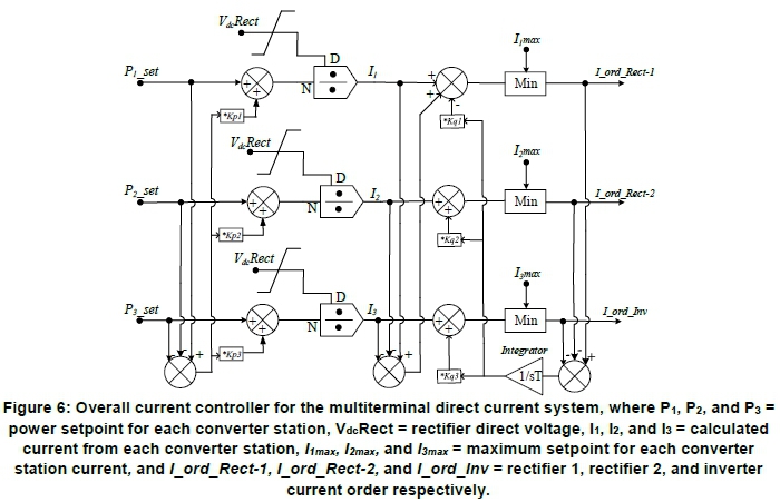
The firing angle (a) order comes from the PI regulator that takes the difference between the commutation margin y (delay between the valve extinction and the voltage of the valve just before turning positive) and the pre-set value of the extinction angle (yo). During a situation where the difference (y - yo) is larger than necessary, the PI controller stops at the a-max, or the firing angle is reduced until y equals the set value. However, during a fault, the inverter has the capability of mode shifting from voltage control to current control. The power controller coordinates and oversees the converter actions of the entire DC link. It takes a variable power order, which when divided with the system voltage gives the current order signals for the inverter. The master controller shown in Figure 6 helps to balance the power and current order of the entire converter by ensuring that DC current summation across all converters equals zero (Σ ldc=0). This controller uses measured DC voltage at each converter station with a pre-set power order to generate the current order for each of the converter systems.
It also compensates for DC line losses and power order compensation by using weighting factors kq and kp respectively. Sharing of excess power order value to avoid overloading any of the substations is done using the kq to fulfil ΣKq=1. Each of the converter stations was also equipped with the voltage-dependent current order limiter (VDCOL) controller, which serves as a corrective measure in aiding the reduction of the current (Idc) that in turn reduces the power (Pdc) transfer across the link during system perturbation. The VDCOL controller reduces the occurrence of commutation failure, especially at the inverter station [24].
3. Results and discussion
The results following a dynamic analysis on PSCAD/EMTDC simulation software include the generator active power, oscillation speed and the generator field voltage. Both scenarios maintained a stable operating state after systems disturbance with positive damping coefficient although with different amplitudes and waveform distortion.
3.1 First scenario
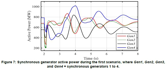
The generators' active power in Figure 7 shows the synchronous generator 2's (Gen_2's) lowest dip of 200 MW during a fault, followed by Gen_1 attributable to the close distance to the transmission line fault.
Gen_4 had the worst post-fault condition, with active power output reaching 1073 MW. Nearly 1.53 pu of its steady-state value following a drop in active power generated from Gen_3 because of a prolonged generator disturbance reaching 3s simulation time on Gen_4. The Gen_3 also followed the same pattern as Gen_4, being similar to each other in A2. The two generators swung together against Gen_1 and Gen_2 in A1, as in Figure 8.

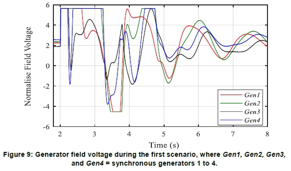
The highest oscillatory modes were recorded in Gen_3 and Gen_4 subplot, increasing up to 1.013 pu because of the accelerating power of the machine in matching up the expected load demand in A2. The system maintained a stable operating condition, however, with high oscillation frequency. The machine field voltage of Gen_1, Gen_2, and Gen_4 in Figure 9 recorded a continuous swing between the minimum and maximum field voltage of -4.53 pu and 5.64 pu, respectively, until 6.5s simulation time.
The generators' AVR and PSS controller had already yielded its damping torque in maintaining stable operating points, as seen in the field voltage, thus generating an insufficient damping coefficient to restore the system to its steady-state operating point quickly. A further increase in the fault clearing time (tc = 0.19s) would lead to the incapability of the generator controllers to fully restore the system to its system steady-state stability point.
3.2 Second scenario
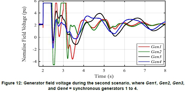
The results were compared to those of the first scenario to determine which of the interconnections performed better in reducing the inter-area oscillation. The active generator power in Figure 10 showed a reduced power swing during a system disturbance. Gen_3 recorded the highest power amplitude of 905 MW after the fault because of continuous generator fault on Gen_4, resulting in higher inertia in restoring the steady-state operating point of the entire system. This led to a lower generator swing for the post-fault condition as the MTDC link reduced the transfer of fault current from one generating station to another, unlike the first scenario where the generator fault on Gen_4 caused a large reduction in power generated by Gen_3. After eight cycles of simulation time, sufficiently damped generator oscillations with low magnitudes were all recorded as all the oscillation amplitude were quickly damped from the enhancement gotten from the robust MTDC controller support. Also, the generators' oscillations were fully damped at exactly 12s simulation time. Figure 11 shows the generators' frequency swings. Being an incoherent machine system with A1 having different inertia constants to A2, the generators in A1 swings against those in A2. Gen_1 and Gen_2 in A1 recorded the highest oscillation value of 1.0075 pu. The generator field voltage, shown in Figure 12, reached the first maximum swing value of 5.64 pu at 2s. With the MTDC link in operation, this value recorded a slight reduction in the minimum and maximum swing compared to the AC lines operating scenario.


After eight cycles of simulation time, sufficiently damped generator oscillations with low magni tudes were all recorded as all the oscillation amplitude were quickly damped from the enhancement gotten from the robust MTDC controller support. Also, the generators' oscillations were fully damped at exactly 12s simulation time. Figure 11 shows the generators' frequency swings. Being an incoherent machine system with A1 having different inertia constants to A2, the generators in A1 swing against those in A2.
Gen_1 and Gen_2 in A1 recorded the highest oscillation value of 1.0075 pu. The generator field voltage in Figure 12 reached the first maximum swing value of 5.64 pu at 2s. With the MTDC link in operation, this value recorded a slight reduction in the minimum and maximum swing compared with the AC lines operating scenario.
Figure 13 shows the active DC power across the three-terminal converters. The Rect-1 station (800 MW converter connected to Gen_4 in replacement of line L10_11b) showed an increase in power transfer across the link between 2 s and 4s simulation time because of the large reduction in power generated by Gen_3 because of the system's disturbance.

While Rect-1 (300 MW converter link connected in replacement of line L7_8b and L8_9b) recorded a zero power dip during the short circuit fault, it was not affected by the generator power swing. Also, a temporary overcurrent can be seen at the inverter's current plot in Figure 14. This current overshoot is due to fault current contribution from all parallel converters (minimal in monopole point-to-point connection).
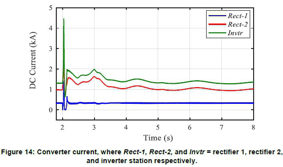
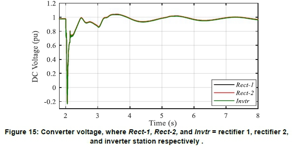
However, this temporary spike is in an acceptable limit as the thyristor valve for a multi-terminal system is rated to allow twice the rated valve current to keep it from being damaged. The DC voltage plot in Figure 15 shows converter voltage dipping down to 0.2 pu during the fault. This situation could further lead to a reverse in the direction of power flow. However, with the converter current still at positive zero value, this caused a fixed zero power transfer across the link during the two short-circuit fault; thus, the reverse power flow into both rectifiers' stations is thereby avoided with the help of the converter control setup.
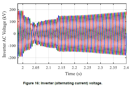
The three-phase AC voltage plot shown in Figure 16 recorded a minimal dip at 2.0s and transient distortion at 2.05s, but recorded no cases of commutation failure at the inverter station during and after the fault.
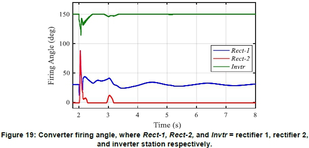
The VDCOL plot during the fault condition is shown in Figure 17. It reduces the reference current in Rect-2 to allow minimum power flow across the link. Figure 18 shows that the inverter mode shifted from the current control setpoint to the voltage control point during the TFSC fault, thus maintaining a fixed voltage profile across all the converter stations during the fault. The converter-firing angle in Figure 19 recorded a sharp decrease at the inverter station because of the TFSC, while a transient increase was noticed across all rectifiers' valves.

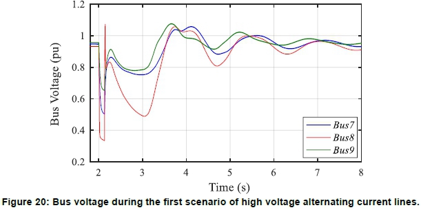
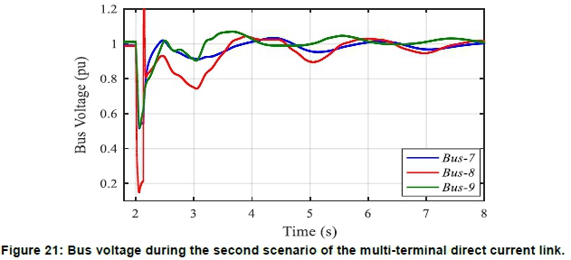
Following the fault, Bus_7, 8 and 9 were monitored for the dynamic response of the voltage profile. The bus voltages for both scenarios are presented in Figures 20 and 21, respectively. During the first scenario of HVAC lines, the dynamic response showed that Bus_8 is the weakest in the network because of its distance from both areas' generating plants, followed by Bus_7. This plot also showed that the increment in the transmission distance between Bus_10 and Bus_11 has no reducing effect on Bus_9 voltage profile compared with other buses in both scenarios. Figure 21 also shows that the second scenario (with MTDC link) generated fewer oscillations, with Bus_8 still having the worst post-fault oscillations. The system-voltage profile was improved during the second scenario as all the system's steady conditions were stabilised after about four cycles.
Inter-area power transfer between Bus_7 and Bus_9 shown in Figure 22 confirmed the very slow damping of the inter-area power oscillations for the initial scenario of having only AC transmission lines. The active power during this scenario had undergone a transient post-fault condition, thus contributing more to the oscillations before steady-state condition could be reached.
Figure 22 shows that, for the same disturbance with the introduction of the MTDC link, the damping on the inter-area power oscillations increased as the amplitude of the inter-area power transfer across the areas recorded a significant positive damping rate, thereby providing more stable steady-state operating conditions. The active power transfer during this scenario corresponds to the power across the AC lines (L7_8 to L8_9) plus the DC power across Rect-1 station. It shows that the damping ratio generated a 37% reduction of the initial value of the oscillation amplitude in the third oscillation period.
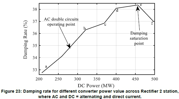
Figure 23 shows the damping rate value recorded across the inter-area busbar after the third oscillation for a different Pdc setpoint for Rect-2. Points a to b, with active power of 200-340 MW) showed a linear increase in the damping support from the MTDC link with the first scenario of double AC lines falling in between this operating point, providing approximately 34.7% damping after the third oscillation. Points b to c recorded a small increase, while c to d recorded a significant increase in the damping support given by the MTDC link. Point e witnessed the damping saturation point where a further increase in the Pdc for Rect-2 brought about a decrease in the damping support to the system oscillation amplitude due to excess active power in the entire AC/DC system.
4. Conclusions
Two methods of power transmissions were carried out on a modified Kundur two-area four-machine system with regard to the impact of a fault on the AC-DC networks. Following the system fault on the test network, the poorest damped modes of the active power and synchronous speed of the generator in each grid scenarios were observed during a time-domain response. These all confirmed that the multi-terminal direct current (MTDC) systems implemented in this study provide a better damping of the oscillation with reduced amplitudes compared with the first scenario with high voltage alternating current lines only. The results also showed that excess power transfer across the MTDC link has a detrimental impact on the AC network inter-area oscillation. Therefore, a better control of the current order (Iorder) added more inertia support to the synchronous generators by providing sufficient controllability to the system and finally leading to better damping of the generator inter-area swings.
Note
1. A supplementary file contains tables with: 1) mul-titerminal high voltage direct current data; 2) synchronous machine data; and 3) transmission line data; as well as a nomenclature list. It is available from the JESA website at DOI: https://dx.doi.org/10.17159/2413-3051/2020/v31i1a7430.
Acknowledgements
The authors acknowledge the support by Eskom Power Plant Engineering Institute Specialization Centre for HVDC and FACTS; Eskom Tertiary Education Support Programme and the DTI.
Author roles
Oluwafemi Oni: Model development, simulations, interpretation of results, and manuscript write-up. Andrew G. Swanson: Research formulation, supervisor, editing, and review for quality assurance. Rudiren Pillay Carpanen: Research formulation, supervisor, editing and technical advice.
References
Abdelsalam, H. A. and Abdelaziz, A. Y. 2013. Wide-area automatic voltage regulators controller for damping oscillations based on inter-area modes. Electric Power Components and Systems, 41(9), 912-925. [ Links ]
Abdlrahem, A., Hadidi, R., Karimi, A., Saraf, P. and Makram, E. 2017. Fixed-order loop shaping robust controller design for parametric models to damp inter-area oscillations. International Journal of Electrical Power & Energy Systems, 88, 164-174. [ Links ]
Abdulrahman, I. and Radman, G. 2018. Wide-area-based adaptive neuro-fuzzy SVC controller for damping interarea oscillations. Canadian Journal of Electrical and Computer Engineering, 41(3), 133-144. [ Links ]
Ademola-Idowu, A. and Zhang, B. 2018. Optimal design of virtual inertia and damping coefficients for virtual synchronous machines. arXiv preprint arXiv:1806.08488. [ Links ]
Anderson, P. M. and Fouad, A. A. 2008. Power system control and stability: John Wiley & Sons. [ Links ]
Azad, S. P., Iravani, R. and Tate, J. E. 2013. Damping inter-area oscillations based on a model predictive control (MPC) HVDC supplementary controller. IEEE Transactions on Power Systems, 28(3), 3174-3183. [ Links ]
Canizares, C., Fernandes, T., Geraldi, E., Gerin-Lajoie, L., Gibbard, M., Hiskens, I. and DeMarco, F. 2016. Benchmark models for the analysis and control of small-signal oscillatory dynamics in power systems. iEEE Transactions on Power Systems, 32(1), 715-722. [ Links ]
Eftekharnejad, S., Vittal, V., Heydt, G. T., Keel, B. and Loehr, J. 2013. Small signal stability assessment of power systems with increased penetration of photovoltaic generation: A case study. iEEE Transactions on Sustainable Energy, 4(4), 960-967. [ Links ]
Elizondo, M. A., Fan, R., Kirkham, H., Ghosal, M., Wilches-Bernal, F., Schoenwald, D. and Lian, J. (2018). Interarea oscillation damping control using high-voltage DC transmission: A survey. iEEE Transactions on Power Systems, 33(6), 6915-6923. [ Links ]
Grigsby, L. L. 2016. Power system stability and control: CRC Press. [ Links ]
Kundur, P., Balu, N. J. and Lauby, M. G. 1994. Power system stability and control (Vol. 7): McGraw-hill, New York. [ Links ]
Li, Y., Rehtanz, C., Ruberg, S., Luo, L. and Cao, Y. 2012. Wide-area robust coordination approach of HVDC and FACTS controllers for damping multiple interarea oscillations. iEEE transactions on power delivery, 27(3), 1096-1105. [ Links ]
Liu, H., Zhu, L., Pan, Z., Bai, F., Liu, Y., Liu, Y. and Bhatt, N. 2017. ARMAX-based transfer function model identification using wide-area measurement for adaptive and coordinated damping control. iEEE Transactions on Smart Grid, 8(3), 1105-1115. [ Links ]
Milano, F., Dõrfler, F., Hug, G., Hill, D. J. and Verbic, G. 2018. Foundations and challenges of low-inertia systems. Paper presented at the 2018 Power Systems Computation Conference (PSCC). [ Links ]
Mondal, D., Chakrabarti, A. and Sengupta, A. 2020. Power system small signal stability analysis and control. Academic Press. [ Links ]
Oni, O. E., Swanson, A. G. and Carpanen, R. P. 2018. Modelling and control of multiterminal LCC HVDC. Paper presented at the 2018 IEEE PES/IAS PowerAfrica. [ Links ]
Oni, O. E., Swanson, A. G. and Carpanen, R. P. 2019. Small signal stability analysis of a four machine system with strategic placement of monopolar LCC-HVDC link. Paper presented at the 2019 Southern African Universities Power Engineering Conference/Robotics and Mechatronics/Pattern Recognition Association of South Africa (SAUPEC/Rob-Mech/PRASA). [ Links ]
Preece, R., Milanovic, J. V., Almutairi, A. M. and Marjanovic, O. 2012. Damping of inter-area oscillations in mixed AC/DC networks using WAMS based supplementary controller. IEEE Transactions on Power Systems, 28(2), 1160-1169. [ Links ]
Saghafi, H., Karshenas, H. and Bakhshai, A. 2015. Application of integrated series compensator in damping power oscillations in standalone microgrids. Canadian Journal of Electrical and Computer Engineering, 38(1), 2-9. [ Links ]
Sanchez-Gasca, J., Wang, L. and Kundur, P. S. 2017. Small-signal stability and power system oscillations. Power system stability and control. McGraw-Hill, New York. [ Links ]
Siemens. Small signal stability analysis module: Network eigenvalue analysis for PSSCE. Retrieved from https://www.siemens.com/content/dam/webassetpool/mam/tag-siemens-com/smdb/energy-management/services-power-transmission-power-distribution-smart-grid/consulting-and-planning/power-systems-simulation-software/psse-small-signal-stability-analysis-sag.pdf. [ Links ]
Wandhare, R. G. and Agarwal, V. 2014. Novel stability enhancing control strategy for centralized PV-grid systems for smart grid applications. IEEE Transactions on Smart Grid, 5(3), 1389-1396. [ Links ]
Witzmann, R. 2001. Damping of interarea oscillations in large interconnected power systems. Paper presented at the Proceedings on the International Conference on Power Systems Transients. [ Links ]
Zou, X. 2018. Frequency and damping characteristics of generators in power systems. MSc in Electrical Engineering dissertation. Virginia Tech. [ Links ]
* Corresponding author: Tel: 612251985. email: maxiphem@yahoo.com

