


Servicios Personalizados
Articulo
 Inglés (pdf)
 Articulo en XML
 Referencias del artículo
Indicadores

Links relacionados
-
 Citado por Google
 -
 Similares en Google
Compartir

 Permalink
Journal of Energy in Southern Africa
versión On-line ISSN 2413-3051
versión impresa ISSN 1021-447X
J. energy South. Afr. vol.30 no.3 Cape Town ago. 2019
http://dx.doi.org/10.17159/2413-3051/2019/v30i3a5691
ARTICLES
Techno-economic evaluation of five-level nested neutral point clamped converter topology for transformer-less connection of high-power wind energy conversion systems
Akinola A. Ajayi-ObeI, *; Mohamed A. KhanII; Paul S. BarendseIII
IAdvanced Machines Energy Systems Research Group, Department of Electrical Engineering, Faculty of Engineering and the Built Environment, University of Cape Town, Cape Town, South Africa. https://orcid.org/0000-0001-5566-2018
IIAdvanced Machines Energy Systems Research Group, Department of Electrical Engineering, Faculty of Engineering and the Built Environment, University of Cape Town, Cape Town, South Africa. https://orcid.org/0000-0002-1438-5162
IIIAdvanced Machines Energy Systems Research Group, Department of Electrical Engineering, Faculty of Engineering and the Built Environment, University of Cape Town, Cape Town, South Africa. https://orcid.org/0000-0002-5598-5068
ABSTRACT
Developers and operators are interested in improving the reliability and reducing the associated costs of wind power plants (WPPs) because of the continuous increase in the power capacity of wind energy conversion systems (WECSs) and the increasing development of WPPs. The electrical subsystem of the WPP experiences the highest failure rate and constitutes a significant proportion of its total cost. Reliability of the WECS can be increased and its cost reduced by eliminating the wind turbine transformer from the electrical subsystem. This study gives a techno-economic evaluation of a five-level nested neutral point clamped (NNPC) converter topology for transformer-less connection of high- power WECSs. The approach entailed the calculation of reliability of five-level NNPC converter topology deployed in the grid-side of a WECSs. This method presents a mathematical formula for deriving the reliability of a five-level NNPC converter topology by using the reliability block diagram and reliability estimation-based models in the military handbook (MIL-HDBK-217F). The cost analysis model shows that the total cost of the five-level diode clamped converter topology was higher than the five-level NNPC converter topology. The study could be extended by carrying out accurate modelling of the mission profile of the presented converter by using multi-domain simulation technique.
Highlights:
• Power semiconductor devices and capacitors accounts for 50% of converter failure.
• Converter topology with fewer capacitors are more reliable and cost-effective.
Keywords: diode-clamped converter topology, wind turbine transformer, reliability analysis
1. Introduction
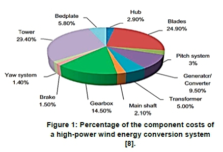
The power converter subsystem of a wind energy conversion system (WECS) is rated as one of the least reliable components of the system [1, 2]. It has been reported that about 13% of the failure in installed onshore WECS are caused by faults in the power converter subsystem [3]. Environmental factors such as ambient temperature, humidity, and the average wind speed in the vicinity have been identified as the main cause of failure in the power converter of a WECS [2]. Based on previous reliability studies, the electrical subsystem of the WECS was identified to have a high percentage of failure, mainly caused by the variable nature of wind [4-7]. The wind turbine (WT) transformer was identified as one of the least reliable and costly components of the electrical subsystem, as shown in Figure 1 [7-9].
It is, therefore, vital to ascertain the major causes of failure of WT transformers in a WECS. The main factors responsible for the frequent failure of WT transformers were identified as the variable nature of wind, utilisation of conventional power transformers, and compliance to grid codes [5, 6]. The variable nature of wind gives a low loading factor of WT transformer (20 - 35%), which results in significant core losses [5, 6], and results in multiple loading cycles in the transformer, thereby increasing its aging rate [5, 6]. A sudden reduction in the grid voltage caused by voltage unbalance results in an inrush of current in the transformer, which increases the electrical and thermal stress on its windings [5]. These causes of failure can, however, be minimised by eliminating the WT transformer from the WECS [511].
A conventional wind power plant (WPP) consists of two transformers: the WT and substation transformers [3-5]. The term 'transformer-less configuration' in the present study refers to the elimination of the WT transformer from the WECS to improve the performance and reducing the cost of the system [10]. Previous reliability studies on high-power WECSs focused on the different components of the turbine based on reported failure statistics [7-11]. This study investigates the reliability of the five-level NNPC converter topology deployed in the power conversion stage of transformer-less configurations. The single-phase and three-phase five-level NNPC circuitry is shown in Figure 2.

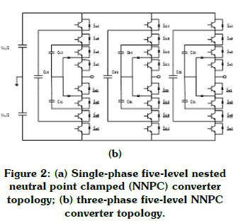
A single-phase five-level NNPC topology is made up of three flying capacitors (cfx3, Cfx2, Cfx1; x = a, b, c), four pairs of complementary power semiconductor switches (sx4 - Sx4, Sx3 - Sx3, Sx2 - χ = a, b, c), and two clamping di-odes(Dx1,Dx2; χ = a, b, c) [13, 14]. The outer flying capacitor(cfx3) is rated at three quarters of the dc-link voltage (3/4 Vdc) and the inner flying capacitors(cfx2, Cfx1) is rated at one quarter of the dc-link voltage (1/4Vdc) [12-14]. The maximum voltage across each power semiconductor switch is rated at one quarter of the dc-link voltage (1/4 Vdc)[13, 14].
The two main techniques presented in literature for reliability analysis of multilevel converter topologies are reliability estimation based on models in the military handbook (MIL-HDBK-217F) [15], and a physics-of-failure approach based on the multi-disciplinary analysis of the system [16]. Most of the failure mechanisms associated with the physics-of-fail-ure approach for multilevel converter applications have not been ascertained, despite the higher accuracy and reliability of the physics-of-failure approach than the reliability estimation-based on model technique [17].
Reliability estimation-based was therefore used in the present study. The study was based on the hypothesis that the reliability, efficiency and installation costs of a WECS can be improved by eliminating the WT transformer from the WPP. This implies that the grid-side converter topology of the WECS is extended to perform the conventional functions of the WT transformer [10, 11]. Therefore, a grid-side multilevel converter topology is required for the transformer-less connection of a high-power WECS because of the voltage rating of the commercial power semiconductor devices [10]. This study also examined the reliability and economic cost of deploying a grid-side multilevel converter topology for the transformer-less connection of a high-power WECS.
2. Methodology
The reliability estimation method was used to evaluate the five-level NNPC converter topology by identifying the fragile components in the system and determining the failure rate of the fragile components based on the data in MIL-HDBK-217F.
2.1 Fragile components in a five-level NNPC converter topology
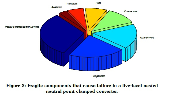
The two main components responsible for most failures in a five-level NNPC converter topology are capacitors and power semiconductor devices. In Figure 3, the converter failure is accounted for by 21% capacitors, 32% power semiconductor devices, 8% printed circuit boards (PCBs), 18% gate drivers, 9% passive components (such as inductors, and resistors) and 12% connectors [1, 2, 18].
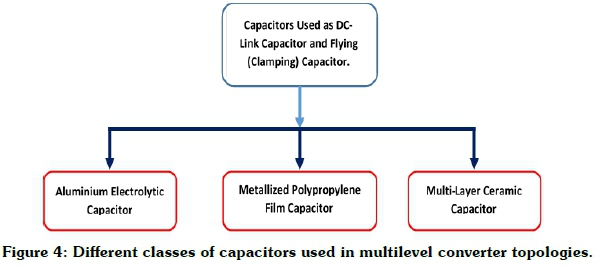
Capacitors
There are three classes of capacitors used in multilevel converter applications: aluminium electrolytic capacitors, metallised polypropylene film capacitors and multi-layer ceramic capacitors [19], as shown in Figure 4. Each has distinct characteristics, advantages and shortcomings for wind energy applications [19]. The aluminium electrolytic capacitor is, however, widely used in grid-side power converters of WECS because of its high energy density, high capacitance, and cost effectiveness [19, 20], although it is the least reliable type of capacitor because of the nature of its dielectric material [19, 21]. The degradation of the electrolyte, which is the dielectric material in the aluminium electrolytic capacitor is caused by the ambient temperature, operating voltage of converter and ripple current of the converter [20].
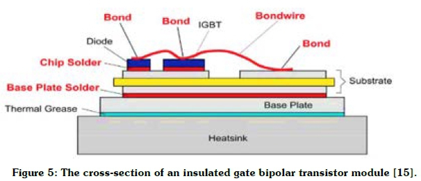
Power semiconductor devices
Insulated gate bipolar transistors (IGBTs) and power diodes are the main power semiconductor devices used in the five-level NNPC converter topology. Both the module and press-pack packaging technologies are used for the medium voltage IGBT used in multilevel converter topologies. The IGBT module is mostly used in multilevel converter applications because of cost and ease of implementation [10]. It is, however, prone to thermomechanical fatigue stress and catastrophic events that occur during the operation of the converter [22]. A cross-section of the IGBT module is shown in Figure 5.
2.2 Reliability analysis of a five-level NNPC converter topology
The reliability of a five-level NNPC converter topology in the grid-side of a transformer-less WECS is estimated based on the component's parameters stated in the military handbook (MIL-HDBK-217F) [15]. The reliability of a single-phase five-level NNPC converter topology is calculated by Equation 1 [17, 23, 24].

where R 1phase sl nnpc (t) is the reliability function of a single-phase five-level NNPC converter, λ iphase 5l_nnpc is the estimated failure rate of a single-phase five-level NNPC converter, and t is the duration of operating a single-phase five-level NNPC converter before a failure occurs. Therefore, the reliability of a three-phase NNPC converter topology used in a transformer-less WECS, is calculated by Equation 2 [23].

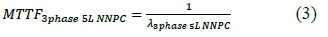
In addition, the mean time to failure (MTTF) of a three-phase five-level NNPC converter topology is calculated by Equation 3 [17, 23, 24].
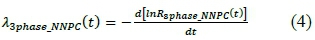
The failure rate of the three-phase five-level NNPC converter topology is obtained by Equation 4.
Failure rate of capacitors in a five-level NNPC converter topology
The failure rate of the aluminium electrolytic capac-Electrolytic _caps) used in the converter topology is given by Equation 5 [15].
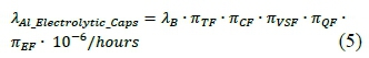
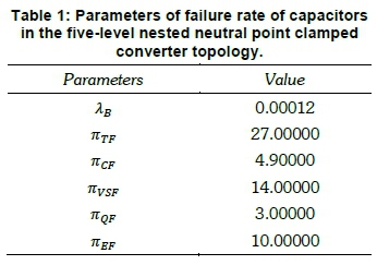
where λΒ is the base failure rate of the aluminium electrolytic capacitor, nTF is the temperature factor of the aluminium electrolytic capacitor, nCF is the capacitance factor of the aluminium electrolytic capacitor, nVSF is the voltage stress factor of the aluminium electrolytic capacitor, Uqf is the quality factor of the aluminium electrolytic capacitor, and nEF is the environmental factor of the aluminium electrolytic capacitor. The parameters in Equation 5 are obtained from MIL-HDBK-217F [15] and presented in Table 1. The value of λAi_mectroiytic_Capsis consequently 6.67 χ 10-6/hours.
Failure rate of power semiconductor devices in a five-level NNPC converter topology
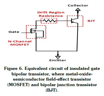
The power semiconductor devices in the NNPC converter topology are the IGBT/diode modules and the clamping diodes (power diodes). The formula for calculating the failure rate of IGBT module is not stated in MIL-HDBK-217F [15]. The failure rate of an IGBT module is evaluated based on the equivalent circuit for modelling its operation, which consists of an N-channel metal-oxide-semiconductor field-effect transistor, drift region resistance (Rdríft), and a positive-negative-positive bipolar junction transistor, as shown in Figure 6 [25]. The drift region is shortened in punch-through IGBT to reduce the on-state loss, while the drift region resistance is considered negligible in estimating the failure rate of the IGBT module [25]. The failure rate of the IGBT module (λΙ0ΒΤ) can, therefore, be obtained using Equation 6 [26].

where

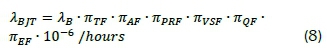
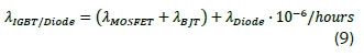
where nAFis the application factor, and nPRFis the power rating factor. The failure rate of an IGBT/di-ode module (λιαβτ/Diode) is given by Equation 9.
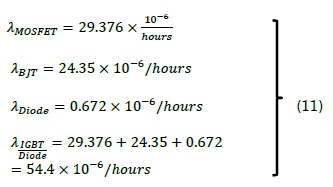
The failure rate of the diode (λDiode) is calculated by Equation 10.
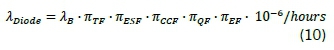
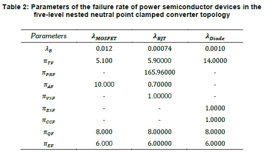
where nESFis the electrical stress factor, and nCCFis the contact construction factor. In Table 2, the values of the parameters in Equations 6 to 10 are presented as obtained from MIL-HDBK-217F [15]. The values of λIGBT/Diodeand λDiodeyield Equation 11.
Reliability block diagram method of a five-level NNPC converter topology
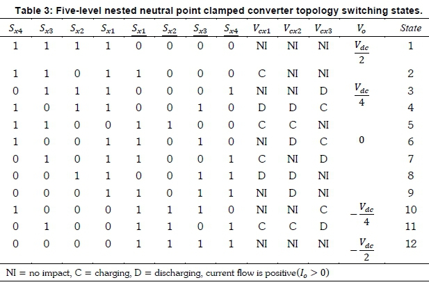
In Figure 7(a), the single-phase five-level NNPC converter topology is classified into a reliability block diagram based on the switching state of the power semiconductor devices. The topology is divided into four switching states, i.e., switching states 1, 2, 3 and 4 based on the complementary switching of the power semiconductor devices, as shown in Table 3. Each switching state can be categorised into cells [24]. Switching states 1, 2, 3 and 4 are therefore, respectively categorised as 'cell 1', 'cell 2', 'cell 3' and 'cell 4'. In Figure 7(b), the reliability block diagram of the five-level NNPC converter topology is presented according to the cell structure of the switching states [24].
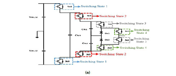
The reliability of a single-phase of the five-level NNPC converter is defined based on series connection of cells and the one-out-of-two redundancy structure of the cells [24], as expressed by Equation 12.

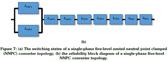
Equation 13 is thus obtained.
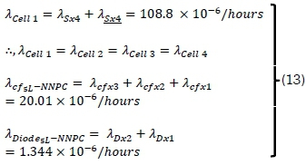
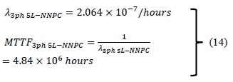
where λCell1is the failure rate of 'cell 1', which consists of the complementary pair of 5x4 and 5x4 IGBT/diode modules; λ Cell2 is the failure rate of 'cell 2', which consists of the complimentary pair of Sx3 and 5x3 IGBT/diode modules; XCell3 is the failure rate of 'cell 3', which consists of the complimentary pair of Sx2 and 5x1 IGBT/diode modules; λ CeU4 is the failure rate of 'cell 4', which consists of the complimentary pair of 5x1 and 5x2 IGBT/diode modules; λCfj,L-NNPCis the total failure rate of flying capacitors in the five-level NNPC converter (consists of outer flying capacitor C/x3, and inner capacitors Cfx2, C/x1); and λDiode_5L-NNPCis the total failure rate of the clamping diodes in the five-level NNPC converter consisting of Dx2 and Dxl. Therefore, the failure rate (λ3ph sl-nnpc) and MTTF (MTTF3ph 5L-NNpc) of a three-phase five-level NNPC converter topology are calculated with Equations 3 and 4 respectively, to yield Equation 14.
2.3 Cost analysis of a five-level NNPC converter topology
The total cost of a three-phase five-level NNPC converter topology consists of the initial installation cost, operational and maintenance cost, and power loss cost [17, 27]. The cost of the power semiconductor devices in a five-level NNPC converter topology contributes about 40% of the total initial cost of the topology [28]. Components of a three-phase five-level NNPC converter comprise IGBT/diode modules, clamping diodes, flying capacitors, and gate drivers, as shown in Figure 2(b). The 4.5 kV IGBT/diode module is selected for the NNPC converter topology because of its low conduction and low switching losses, amongst the various commercially available 4.5 kV IGBT/diode modules; the CM600HB-90H manufactured by POWEREX is chosen because of superior performance [29]. The costs of one IGBT/diode module, a clamping diode, a flying capacitor, a gate driver circuitry, and a heatsink are EUR 990, EUR 312, EUR 35, EUR 135, and EUR 245 respectively [28, 30]. Therefore the total initial installation cost (Cinst) consists of the cost of the converter (Cconverter) and cost of the cooling system (Ccoollng), as expressed in Equation 15 [17].
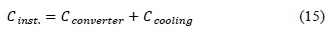
where Cconverterand Ccoolingare defined by Equations 16 and 17 respectively.
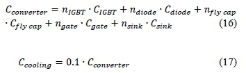
where nIGBTis the number of IGBT/diode module in the topology, C1GBTis the cost of an IGBT/diode module, ndiodeis the number of clamping diode, Cdiodeis the cost of a clamping diode, n.fly capis the number of flying capacitor, Cfiycapis the cost of a flying capacitor, ngateis the number of gate drivers, Cgate is the cost of a gate driver, nsinkis the number of heatsink and Csinkis the cost of a heatsink. The operational and maintenance cost(C0&M )includes; scheduled (Cscheduled ),unscheduled(Cunseheduied )and downtime cost (Cdowntime)[17, 27]. Therefore the C0&Mis expressed by Equation 18.

The scheduled maintenance cost is estimated at 5% of the initial installation cost, derived by Equation 19 [17, 31].

The unscheduled maintenance cost of the three-phase five-level NNPC converter in a WECS operating for 20 years is stated in Equation 20.
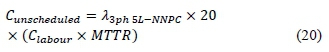
where Clabouris the cost of labour and travel per repair; the labour and travel cost per failure is estimated at EUR 300/kW/day [31], MTTR is the mean-time-to-repair of the three-phase converter topology. The repair time frame for a failed component in a converter is derived as 24 days [17, 32], therefore, MTTR is derived as Equation 21.
where μ is defined by Equation 22.
The timeframe for replacing a faulty component is stated as seven days [27], with a financial loss (floss) of EUR 2 per hour; thus, the downtime cost for 20years is derived using Equation 23.
The power loss cost is assumed to be EUR 0.10/kWh [17, 27], so the total power loss cost of the converter for one year is determined by Equation 24.

where Ρ is the power rating of the three-phase NNPC converter topology. The total cost of the three-phase NNPC converter topology is thus expressed in Equation 25.
3. Results and discussion
The initial installation costs of the five-level NNPC converter topology and five-level DCC topology were compared. The individual values of the initial installation cost components were calculated using Equations 12 to 14, as expressed in Section 2. Figures 2(b) and 8 show the respective circuitries of the five-level NNPC and five-level DCC topologies.
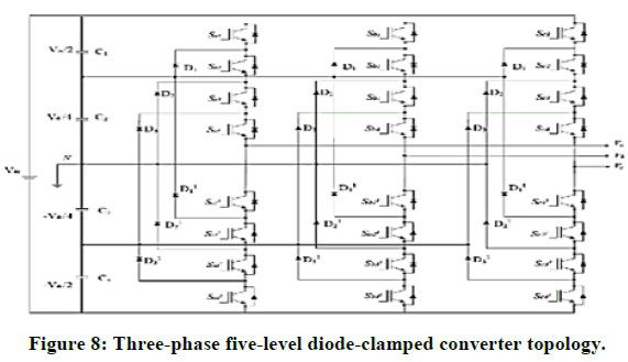
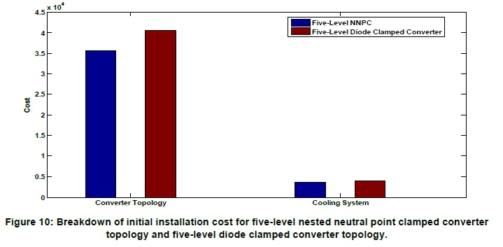
The diode-clamped converter topology is the most used converter topology in wind energy applications because of its simple circuitry [11]. The major drawback of a five-level DCC topology is the uneven distribution of losses amongst power semiconductor devices [11, 16]. A transformer-less five-level DCC topology was connected directly to the grid in a static synchronous compensator application [33]. This topology requires extensive voltage balancing algorithm for the multiple direct current (dc)-link capacitors, as shown in Figure 8. The multiple network of clamping diodes in the five-level DCC topology increases the cost and power loss of the converter. However, the three-phase five-level NNPC topology consists of two dc-link capacitors, six clamping diodes, and twenty-four IGBT/diode modules, as shown in Figure 2(b). The broken-down cost of converter components in the two converter topologies are compared in Figure 9. As stated earlier, the cost of the clamping diodes in the five-level DCC topology is higher, and the cost of the heatsink deployed in the DCC topology is higher. Therefore, the initial installation and cooling system costs of the five-level DCC topology are higher, as shown in Figure 10.
4. Conclusion
This study examined a comprehensive reliability estimation method and reliability block diagram to evaluate the failure rate of a five-level nested neutral point clamped converter topology. A mathematical formula was derived to calculate the reliability of a five-level NNPC converter topology deployed in the grid-side of a wind energy conversion system. It was found to be more expensive to deploy a five-level diode-clamped converter topology in a transformerless wind energy conversion system than to deploy a five-level NNPC converter topology.
Acknowledgments
The authors gratefully acknowledge the technical officers of the Advance Machines Energy Systems research group in the Machines Laboratory of the Department of Electrical Engineering, University of Cape Town.
Author roles
Akinola A. Ajayi-Obe: Project initiator, research formulation, write-up and analytical implementation.
Mohamed A. Khan: Project supervision, research formulation and research funding.
Paul S. Barendse: Project supervision, research formulation and research funding.
References
[1] Yang, S., Bryant, A., Mawby, P., Xiang, D., Ran, L. and Tavner, P. 2011. An industry-based survey of reliability in power electronic converters. IEEE Transaction on Industry Applications 47(3): 1441-1452. [ Links ]
[2] Fischer, K., Stalin, T., Ramberg, H., Wenske, J., Wetter, G., Karlsson, R. and Thiringer, T. 2015. Field-experience based root-cause analysis of power converter failure in wind turbines. IEEE Transaction on Power Electronics 30(5): 2481-2493. [ Links ]
[3] Wilkinson, M. and Hendriks, B. Report on wind turbine reliability profiles - field data reliability analysis. RELIAWIND Project Report. https://www.Reliawind.eu/files/fileinline/110502_Reliawind_Deliverable_D.1.3ReliabilityProfilesResults.pdf. [ Links ]
[4] Reder, M.D., Gonzalez, E. and Melero, J.J. 2016. Wind turbine failures - tackling current problems in failure data analysis. Journal of Physics: Conference Series 753: 072027. [ Links ]
[5] Jose, G. and Chacko, R. 2014. A review on wind turbine transformer. Annual International Conference on Emerging Areas: Magnetics, Machines and Drive, Kottayam, India, 24-26 July 2014: 1- 7. [ Links ]
[6] Remington, K. and Steeber, T. 2010. Why do transformers fail often? [Online]. Available: http://www.windpow-erengineering.com/featured/business-news-projects/why-do-wind-turbine-transformers-fail-so-often/. [ Links ]
[7] Ribrant, J. and Bertling, L.M. 2007. Survey of failures in wind power systems with focus on swedish wind power plants during 1997-2005. IEEE Transaction on Energy Conversion. 22(1):167-173. [ Links ]
[8] Perez, J.M., Marquez, F., Tobias, A. and Papaelias, M. 2013. Wind turbine reliability analysis. Renewable and Sustainable Energy Reviews 23: 463-472. [ Links ]
[9] Spinato, F., Tavner, P.J., Van Bussel, G.J.W. and Koutoulakos, E. 2008. Reliability of wind turbine subassemblies. IET Renewable Power Generation 3(4): 387-401. [ Links ]
[10] Blaabjerg, F., Liserre, M., and Ma, K. 2012. Power electronics converter for wind energy systems. IEEE Transaction on Industry Application 48(2):708-720. [ Links ]
[11] Yaramasu, V., Wu, B., Sen, P.C., Kouro, S. and Narimani, M. 2015. High-Power Wind Energy Conversion Systems: State-of-the Art and Emerging Technologies, Proceedings of the IEEE 103(5): 740-780. [ Links ]
[12] Narimani, M., Wu, B., Cheng, G. and Zargari, N. 2014. A new nested neutral point clamped converter for medium-voltage power conversion, IEEE Transaction on Power Electronics 29(12): 6375-5382. [ Links ]
[13] Narimani, M., Wu, B. and Zargari, N. 2016. A novel five-level voltage source inverter with sinusoidal pulse width modulator for medium-voltage applications. IEEE Transaction on Power Electronics 31(3): 1956-1967. [ Links ]
[14] Ajayi-Obe, A.A. and Khan, M.A. 2017. Analysis of a five-level dual tapped inductor quasi impedance source-nested neutral point clamped converter. Proceeding of the IEEE-Energy Conversion Congress Exposition 2017, Cincinnati, OH, USA, 1-5 October, 2017: 2150-2155. [ Links ]
[15] Military handbook: Reliability prediction of electronic equipment, Dept. Defence, Washington, DC, USA, Dec. 2, 1991, MIL-HDBK-217F. [ Links ]
[16] Ma, K., Liserre, M., Blaabjerg, F. and Kerekes, T. 2015. Thermal loading and lifetime estimation for power device considering mission profiles in wind power converter. IEEE Transaction on Power Electronics 30(2): 590-602. [ Links ]
[17] Yu, X. and Khambadkone, A.M. 2012. Reliability analysis and cost optimization of parallel-inverter system. IEEE Transaction on Industrial Electronics 59(10): 3881-3890. [ Links ]
[18] Wang, H., Zhou, D. and Blaabjerg, F. 2013. A reliability-oriented design method for power electronic converters. 28th Annual Applied Power Electronics Conference and Exposition 2013, Long Beach, CA, USA, 17-23 March, 2013: 2921-2928. [ Links ]
[19] Wang, H. and Blaabjerg, F. 2014. Reliability of capacitors for dc-link applications in power electronic converters - an overview. IEEE Transaction on Industry Application 50(5): 3569-3579. [ Links ]
[20] Jedtberg, H., Langwasser, M., Zhu, R., Buticchi, G., Ebel, T. and Liserre, M. 2017. Impacts of unbalanced grid voltages on lifetime of dc-link capacitors of back-to-back converters in wind turbines with doubly fed induction generators. IEEE Applied Power Electronics Conference and Exposition, Tampa, FL, USA, 26-30 March, 2017: 816-823. [ Links ]
[21] Alwitt, R.S. and Hills, R.G. 1965. The chemistry of failure of aluminium electrolytic capacitors. IEEE Transaction on Parts, Materials and Packaging 1(2): 28-24. [ Links ]
[22] Yang, S., Xiang, D., Bryant, A., Mawby, P., Ran, L. and Tavner, P. 2010. Condition monitoring for device reliability in power electronic converters: a review. IEEE Transaction on Power Electronics 25(11): 2734-2753. [ Links ]
[23] Guo, J., Liang, J., Zhang, X., Judge, P., Wang, X. and Green, T. 2017. Reliability analysis of MMCs considering submodule designs with individual or series operated IGBTs. IEEE Transaction on Power Delivery 32(2): 666-677. [ Links ]
[24] Richardeau, F. and Pham, T.T.L. 2013. Reliability calculation of multilevel converters: theory and applications. IEEE Transaction on Industrial Electronics 60(10): 4225-4234. [ Links ]
[25] Mohan, N., Undeland, T.M. and Robbins, W.P. 2003. Power electronics: Converters, applications, and design, third edition, USA: Wiley. [ Links ]
[26] Sutrisno, E. 2013. Fault detection and prognostics of insulated gate bipolar transistor (IGBT) using a k-nearest neighbour classification algorithm. Master of Science thesis, University of Maryland, USA. [ Links ]
[27] Aghdam, F.H. and Abapour, M. 2016. Reliability and cost analysis of multistage boost converters connected to PV panels. IEEE Journal of Photovoltaics 6(4): 981-989. [ Links ]
[28] Sayago, J.A., Bruckner, T. and Bernet, S. 2008. How to select the system voltage of MV drives-a comparison of semiconductor expenses. IEEE Transaction on Industrial Electronics 55(9): 3381-3389. [ Links ]
[29] Fazel, S.S., Bernet, S., Krug, D. and Jalili, K. 2007. Design and comparison of 4-kV neutral-point-clamped, flying-capacitor, and series-connected h-bridge multilevel converters. IEEE Transaction on Industry Applications 43(4): 1032-1040. [ Links ]
[30] Burkart, R. and Kolar, J.W. 2013. Component cost models for multi-objective optimizations of switched-mode power converters. IEEE Energy Conversion Congress and Exposition 2013, Denver, CO, USA, 15-19 September 2013: 2139-2146. [ Links ]
[31] Canada, S., Moore, L., Strachan, J. and Post, H. 2003. Off-grid hybrid systems: maintenance costs. Solar Energy Technology System Symposium. [ Links ]
[32] Begovic, M., Pregelj, A. and Rohatgj, A. 2000. Four-year performance assessment of the 342 kW PV system at Georgia Tech. Conference Record of the 28th IEEE Photovoltaic Specialists Conference 2000, 15-22 September 2000, Anchorage, USA: 1575-1578. [ Links ]
[33] Akagi, H., Fujita, H., Yonetani, S. and Kondo, Y. 2008. A 6.6 kV transformer-less STATCOM based on a five-level diode-clamped PWM converter: system design and experimentation of a 200-V 10-kVA laboratory model. IEEE Transaction on Industry Applications 44(2): 672-680. [ Links ]
* Corresponding author: Tel: +27 21 6504823; email: ajyaki001@myuct.ac.za

