


Services on Demand
Article
 English (pdf)
 Article in xml format
 Article references
Indicators

Related links
-
 Cited by Google
 -
 Similars in Google
Share

 Permalink
Journal of Energy in Southern Africa
On-line version ISSN 2413-3051
Print version ISSN 1021-447X
J. energy South. Afr. vol.28 n.4 Cape Town Nov. 2017
http://dx.doi.org/10.17159/2413-3051/2017/v28i4a2054
ARTICLES
Design of a prototype generator based on piezoelectric power generation for vibration energy harvesting
Lumbumba Taty-Etienne NyamayokaI, II, *; Gloria Adedayo AdewumiII; Freddie Liswaniso InambaoII
IDepartment of Electrical, Electronic and Computer Engineering, Hatfield Campus, University of Pretoria, Pretoria 0002, South Africa
IIDiscipline of Mechanical Engineering, School of Engineering, Howard College Campus, University of KwaZulu-Natal, Durban 4001, South Africa
ABSTRACT
The concept of harvesting energy in the ambient environment arouses great interest because of the demand for wireless sensing devices and low-power electronics without external power supply. Harvesting energy by vibration with piezoelectric materials can be used to convert mechanical energy into electrical energy that can be stored and used to power other devices. This conversion of vibrations (mechanical energy) to electrical energy using piezoelectric materials is an exciting and rapidly developing area of research with a widening range of applications constantly materialising. In this context, the goal of this paper is to develop a comprehensive prototype generator that can harvest vibration energy and convert it to electrical energy by providing the output power for optimisation and its performance. Two setups of prototype are used: a cantilever beam with tip mass at the end, and a cantilever beam without tip mass at the end. Data from the experiment is compared and analysed using MatLab. The results show that the power output of the prototype with the tip mass is greater than the power output without the tip mass. The experimental results led to a power optimisation from that prototype by different characteristic of piezoelectric ceramic plate.
Keywords: power harvesting, energy conversion, ambiant energy, cantilever beam, ceramic material.
1. Introduction
During the last decade, harvesting energy by vibration has received great attention to develop self-powered microelectronic devices in engineering applications including wireless sensors nodes, micro-electro-mechanical systems (MEMS) and electronic devices [1--3]. This was due to the availability of such sources in the ambient environment. Mechanical vibration is a promising alternative source of energy. Energy-harvesting is a technology that permits the conversion of mechanical energy from ambient vibration to electrical energy using different conversion techniques such as electromagnetic, electrostatic or piezoelectric [1]. Piezoelectric energy harvesting has a high-electromechanical coupling effect and requires no external voltage compared with the other two techniques. It is being widely pursued because of the availability of piezoelectric materials of adequate superior performances and the ability to have higher power densities. Vibration energy harvesting must be able to respond to the low frequency and low acceleration vibrations that usually exist in the environment. Moreover, the energy harvesting should generate as much energy as possible to supply enough power for the follow-up loads. Piezoelectric energy-harvesting provides the first comprehensive treatment of distributed parameter electromechanical modelling for energy harvesting with extensive case studies including experimental validations [2]. Piezoelectric materials are natural candidates for designing devices that scavenge ambient vibration sources, which will then be used for powering small electronic devices with a considerably lower power requirement [3].
Several articles and significant research have been devoted to developing and understanding power-harvesting systems, with an emphasis on piezoelectric conversion to generate electricity from vibrations [4-13]. These studies demonstrated the feasibility of using piezoelectric materials as power sources. Fang et al. [4] fabricated a MEMS-based piezoelectric cantilever power generator with a non-integrated proof mass that can generate 2.16 μW from 10 m/s2 vibration acceleration at its resonant frequency of 609 Hz. The nickel metal mass on the tip of the cantilever is used to decrease the structure's resonant frequency for the application under low-frequency vibration, but it cannot to be micro-machined by MEMS technology. Similarly, Liu et al. [5] used the same cantilever structure to construct a power generator array to improve power output and frequency flexibility. Although Liu et al.'s work demonstrated that power density was high, the proof mass was not integrated with the cantilever, which will be an additional difficulty in production. Renaud et al. [6] proposed a fabricated MEMS-based piezoelectric cantilever micro-generator with an integrated proof mass that can generate an average power of 40 μW at 1.8 kHz vibration frequency. Muralt et al. [7] designed and fabricated a micro power generator of thin-film piezoelectric -laminated cantilever with proof mass and interdigitated electrodes that could generate a voltage of 1.6 V and power of 1.4 μW when excited to less than 20 m/s2 vibration acceleration at 870 Hz resonant frequency. Sodano et al. [8] developed a model to predict the amount of power capable of being generated through the vibration of a cantilever beam with attached piezoelectric materials. The model was verified experimentally and proved to be accurate and independent of excitation frequency and load resistance. The model provided a design tool for developing power-harvesting systems by helping to determine the size and extent of vibration needed to produce the desired level of power generation. Lu et al. [9] proposed a novel maximum power point (MPP) tracking scheme to harvest the maximum power from a vibration system. A vibration-based energy-scavenging system based on piezoelectric conversion for micro-power applications was presented. Lu et al.'s measurement results showed that the power-harvesting efficiency of the overall circuitry was higher than 90%. The studies performed by Chen et al. [10] modelled a novel piezoelectric cantilever bimorph micro-transducer electro-mechanical energy conversion based on the curvature basis approach. The analytical model showed that the vibration-induced voltage was proportional to the excitation frequency of the device but inversely proportional to the length of cantilever beam and the damping factor. Chen et al.'s experimental results demonstrated that the maximum output voltage deviated very little from the analytical model. Elvin et al. [11] developed a novel damage detection sensor that was self-powered and able to transmit information wirelessly to a remote receiver. The performance of the sensor was illustrated through the theoretical and experimental analysis of a simple damaged beam. The results showed that a sensor powered through the conversion of mechanical to electrical energy is viable for detecting damage. Zhou et al. [12] proposed and investigated a novel piezoelectric energy harvester with a multimode dynamic magnifier, which is capable of significantly increasing the bandwidth and the energy harvested from the ambient vibration. The design comprises a multimode intermediate beam with a tip mass, called a dynamic magnifier. Patel et al. [13] proposed a versatile model for optimising the performance of a rectangular cantilever beam piezoelectric energy harvester used to convert ambient vibrations into electrical energy. The developed model accounts for geometric changes to the natural frequencies, mode shapes, and damping in the structure.
The most common method used to characterise a vibration energy harvester is to excite the energy harvester under a sinusoidal vibration of its resonant frequency and to measure the output voltage across certain electrical loads. This is the straightest form of evaluating the output power of a vibration energy-harvester. In practical applications, the vibration spectrum usually contains more than one peak at different frequency. It is important to understand whether vibration peaks at other frequencies will affect the performance of the vibration energy-harvester when it works at only one particular frequency [14]. Even so, the performance of vibration energy harvesting under complicated practical vibration is yet to be reported. Research for this paper included developing a cantilever piezoelectric generator of constant width that simplifies the analytical model, and beam fabrication parameters for a mechanical structure to estimate the output voltage for its performance optimisation. Section 2 presents the materials and methodology, while the experimental results are given and discussed in Section 3, and Section 4 provides conclusions.
2. Material and methodology
2.1 Prototype generator
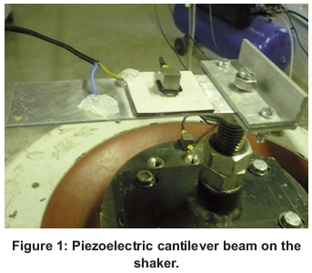
The fabrication of a prototype generator involved attaching a piezoelectric material ceramic plate to the top plane of a steel centre-beam to develop a cantilever piezoelectric generator, as shown in Figure 1.
Two design configurations of the cantilever beam were fabricated and used for this study. In the first setup, the beam was clamped at one end, leaving the other end free, or without tip mass, as illustrated in Figure 2(a). In the second setup, the beam was also clamped at one end, but the other end was with a tip mass as illustrated in Figure 2(b). Both configurations used a piezoelectric material ceramic plate attached to a central brass shim (beam) of length 145 mm, width 45 mm, and thickness 0.8 mm. A material with a high density was used, since this allowed a greater mass value in a restricted volume. Gold, platinum, lead and silver offer high densities of 21.450, 19.300, 11.340 and 10.500 kg/m3 respectively. These materials are hard to obtain and expensive, making steel a good compromise, with a density of 7.930 kg/m3 for the tip mass. The tip mass was obtained from some old brackets, which were first cut using a hacksaw and then filed down to size 30x45x15 mm3 (length χ width χ thickness). The weight value of the tip mass was 15 g. On the beam, the tip mass was fixed by using a screw.


Piezoelectric material when mechanically stressed at a low frequency can be modelled electrically by a time-dependent charge source, which is accumulated in a capacitor. The transduction mechanism can generate electricity using a relative movement of the mechanical stress occurring in the system. The effects of deformation of the strain used in the mechanical system usually use active materials. Whether it is the position or velocity, the relative movement may be coupled to a transduc-tion mechanism. The energy harvester is attached to the vibration source so that the device vibrates together with the source. It starts to generate electricity once the vibration source begins to vibrate. The energy harvester will then convert vibration into electrical energy.
2.2 Piezoelectric material
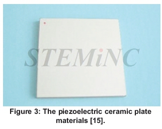
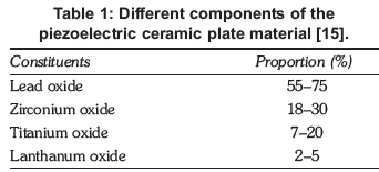
The piezoelectric material chosen for this paper is piezoelectric ceramic plate (lead zirconate titanate) from the STEMiNC company (Steiner & Marrtins, Inc), because it is a well-known and well-characterised material with a high piezoelectric coefficient. Figure 3 shows the piezoelectric device with length-width-thickness 45x45x2.8 mm3, while its constituents are presented in Table 1 [15].
It is ideal for electricity generation and a pressure sensor. There is one silver electrode on each side (S configuration). The red dot marks the positive side and other side is negative. When the material is deformed or stressed, an electric voltage can be recovered along any surface of the material (via electrodes). Therefore, the piezoelectric properties must contain a sign convention to facilitate this ability to recover electric potential in three directions. For the sake of keeping this discussion simple, the piezoelectric material can be generalised for two cases. The first is the stack configuration that operates in the 33 mode and the second is the bender, which operates in the 31 mode [16]. The sign convention assumes that the poling direction is always in the '3' direction; with this point the two modes of operation can be understood.
2.3 Auxiliary equipment
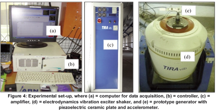
The production of vibration in the laboratory was supplied by the electrodynamics shaker of TIRA Model, Type TV 56263/LS-340. Figure 4 shows the entire experimental set up.
The electrodynamics shaker reproduces a vibration ambient environment under laboratory conditions for testing the dynamic strength and the reliability in all fields of applications of vibrating testing. It is pivoted to enable the excitation in a vertical direction. The digital amplifier is used here to guarantee the performance of the system. In principle, the electrodynamics shaker operates like a speaker, where the armature movement is created by an electric current in the coil. The coil produces a magnetic field opposite to the static magnetic field produced by the electromagnet in the shaker. Electrical power (voltage and current) is provided to the armature of the shaker through the amplifier. It also provides the necessary field power supply for the cooling fan, and auxiliary supplies. In addition to those functions, the role of the amplifier is to monitor the system interlock signals. It shuts down when any abnormality is observed in the vibration system, which is a closed loop. The controller's role is to ensure that what has been programmed is the same as the output signal from the shaker-base accelerometer. The signal produced by the accelerometer passes through typical steps, which include amplification, attenuation, filtration, differentiation, and integration. The accelerometer is a link between the vibrating object and the measurement equipment. All measurements and data are captured by the Puma vibration controller and analysis system software and are displayed on the computer.
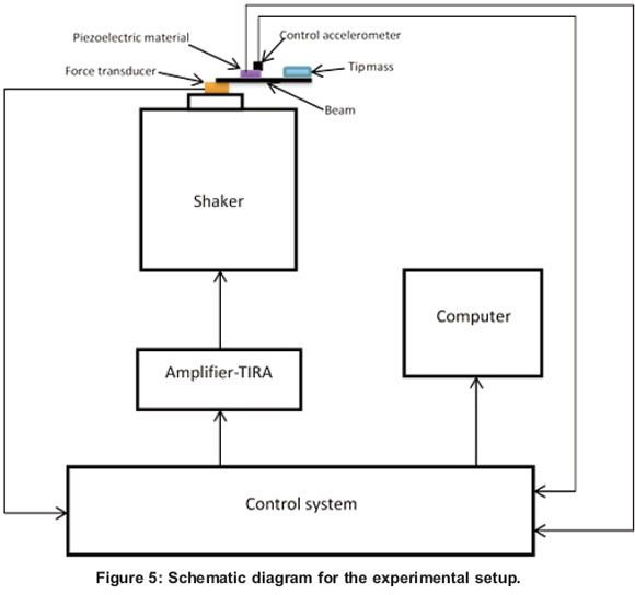
2.4 Methodology
Understanding the mechanism for energy harvesting from vibration using piezoelectric material is essential in determining a suitable design methodology, which is simplified in Figure 5. The mechanical energy from ambient source is produced by an electrodynamics shaker and this energy is converted to electrical energy via the piezoelectric materials and, finally, the electricity is stored [17]. The piezoelectric ceramic plate is attached to the vibration source so that the device vibrates together with the source. The electricity is generated once the vibration source begins to vibrate. The piezoelectric ceramic plate converts vibration into electrical energy. The conversion mechanism in the active materials can generate electricity using a relative movement of the mechanical stress and the effect of deformation of the strain used in the mechanical system.
In this experiment, two types of setup for prototype generators were used to convert the vibration into electrical energy. The first setup (the cantilever beam without a concentrated tip-mass) required a lower vibration frequency, but used a larger energy harvester. The second setup (with the concentrated tip-mass at the end of the cantilever beam) analysed the energy harvested for high frequency vibration using a medium-size energy harvester. Both setups operated at the same range of velocity, but produced different voltage outputs. A Puma vibration controller and analysis system captured the measurements. With scalable hardware and software, the vibration control and analysis system combine the simplicity of operation required for production screening with the power and versatility required for testing prototype generators [18]. The Puma vibration control and analysis system software incorporates high quality data acquisition and signal generation hardware designed with the latest floating-point digital signal-processing technology with patented digital vibration control methods [19]. Adaptive control permits Puma to control and adjust the speed in real time.
3. Results and discusion
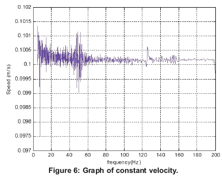
To conduct a performance study, two tests were conducted to collect the data with the two configurations of prototype generator. Those prototype generators were excited at the same constant velocity of 0.1m/sec as shown in Figure 6. The test was repeated to find the resonant frequency and various channels were connected to the output of the prototype generator. For the first setup, the results show that the voltage measured at the point where the beam is at resonance was found to be 4.05 V, which, according to the data collected for Figure 7, corresponds to a frequency of 108.13 Hz.
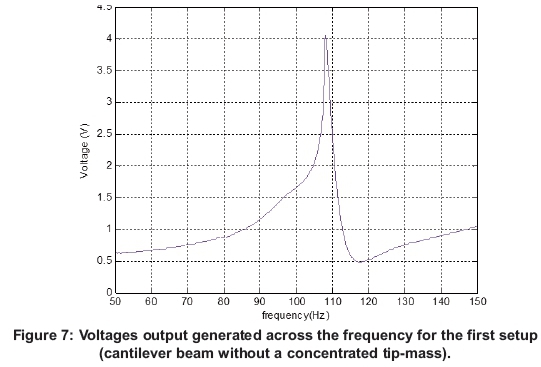
The trend in this graph shows, initially, the value of voltage was high with respect to that of high resonance frequency. This means that the greater portion of voltage available from the alternating current voltage source would be dropped across the prototype generator internal impedance, while the lesser portion of the voltage available would be dropped across the external load resistor. The purpose of finding the resonant frequency of the piezoelectric ceramics material was to characterise piezoelectric ceramics material in terms of maximum power output. Since the resonance condition dictates maximum displacement of the cantilever beam, maximum power output occurs at the resonant frequency, thus characterisation in terms of the maximum power output should be done at resonance.
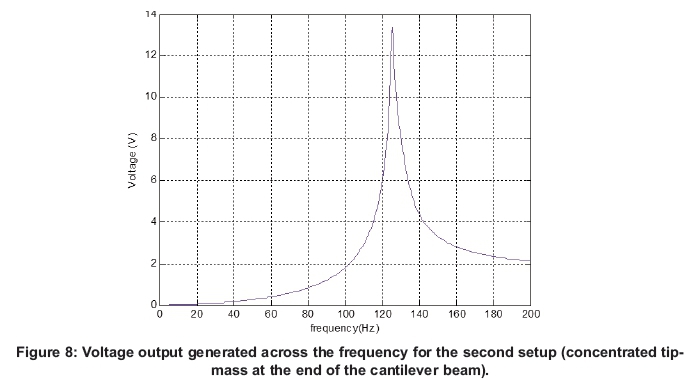
Another possibility was to add a tip mass to the end of the beam, as in the second set up. Adding mass to the end will increase the equivalent mass and increase energy harvested. Energy harvested for the same volume of power dissipated is proportional to its mass equivalent due to the energy density of the heat exchanged. Figure 8 shows the amplitude of the output voltage across the resonance frequency when the tip mass is attach on the beam for the energy harvested. At the same velocity, namely 0.1 m/s, the energy harvesting provides a peak output voltage of 13.35 V at a resonance frequency of 125.5 Hz.
As mentioned above, the voltage output increases for this configuration. As the value of tip mass increases, the amplitude of the voltage output will increase. This numerical study observed that the addition of a weight member increases equivalent weight and therefore, the power factor. These increases result in increased power dissipation and energy density. Addition of a weight member also increases the level of deformation in the piezoelectric material. It was also shown that the strain distribution has substantially the same shape as that of the setup discussed in the previous sub-section, that is to say, the result is a voltage output increase by the end of the experiment. This increase is due to the use of a constant thickness beam with a tip mass at the end.
The output voltage of both configuration prototype generators, namely, the first and second setup, is proportional to the tip mass attached to the beam and this should be maximised provided size and deformation stresses are not exceeded. This geometry can be adjust during the operation to perform the energy harvesting. It has been determined that the harvesting for the peak output voltage correspond at one resonance frequency. The vibration source excites the harvesting via the embedding of the piezoelectric ceramic plate. The cantilever beam has the dimensions defined above (140 mm, 0.8 mm thick and 45 mm wide). From the tip mass selected, it should be noted that the effect of length of the beam on the natural frequency is the same (increase in length causes decrease in the value of the natural frequency). In addition, the amplitude of vibrations has higher values with an increase in the length of the beam, which finally causes higher amplitude of the output voltage. Hence, by increasing the mass of the cantilever beam by a tip mass, the resonant frequency of the beam-mass system decreases. The coefficient does not depend on the beam length, but by increasing beam length the term decreases sharply, and as a result the resonant frequency is decreased as the beam length increases.
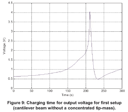
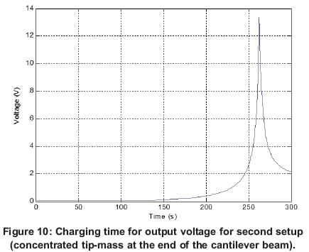
Figures 9 and 10 show the charging time results to reach high voltage for the two designs configurations. As evident in the graphs, the second approach requires more charging time compared to the first setup.
4. Conclusions
This paper designed and tested a comprehensive prototype generator that can harvest available vibration energy and convert it to electrical energy by providing the estimate of output voltage. It was shown that energy harvesting by vibration using piezoelectric materials could bring a peak output voltage between both configurations. The first set up (cantilever beam without a concentrated tipmass) was determined as energy harvesting provided a peak output voltage of 4.05 V at 108.13 Hz resonance frequency. For the second setup (concentrated tip-mass at the end of the cantilever beam), the output voltage measured was 13.35 V at 125.5 Hz resonance frequency. From these results, the amplitude of the output voltage, the impact of a tip mass on the resonance frequency of the energy harvester was found. The first setup had the peak output voltage at a lower frequency compared with the second, which had a peak output voltage at a higher frequency. The prototype generator with a tip mass toward the end of cantilever beam produced decreased resonance frequency as the amplitude of voltage increased, as compared with the prototype generator without a tip mass at the end of cantilever beam. The tip mass produced the quantity of harvested energy and then the output voltage of the generator at resonance frequency was proportional to the tip mass that is glued to the cantilever beam. This is maximised on condition that strain constraints and size are not surpassed.
Acknowledgment
This work was conducted by the Green Energy Solution Research Group, Discipline of Mechanical Engineering at the University of KwaZulu-Natal. The authors are grateful to the Dean of Research, College of Agriculture, Engineering and Science, and the University DVC (Research) of the University of KwaZulu-Natal on behalf of the Vibration Research Testing Centre where the experiments were done.
References
[1] Beeby, S.P, Tudor, M.J. and White, N.M. 2006. Energy harvesting vibration sources for microsystems applications. Measurement Science and Technology, 17: 175-195. [ Links ]
[2] Heung, S.K., Joo-Hyong, K. and Jaehwan, K. A. 2011. Review of piezoelectric energy harvesting based on vibration. International Journal of Precision Engineering and Manufacturing, 12: 1129-1141. [ Links ]
[3] Anton, S.R. and Sodano, H.A. 2007. A review of power harvesting using piezoelectric materials (2003-2006). Smart Materials and Structures, 16: 1-21. [ Links ]
[4] Fang, H.B., Liu, J.Q., Xu, Z.Y, Donga, L., Wang, L., Chen, D., Cai, B.C. and Liu, Y 2006. Fabrication and performance of MEMS-based piezoelectric power generation for vibration energy harvesting. Microelectron Journal, 37: 1280-1284. [ Links ]
[5] Liu, J.Q., Fang, H.B., Xu, Z.Y., Mao, X.H., Shen, X.C., Chen, D., Liao, H. and Cai, B.C. 2008. A MEMS-based piezoelectric power generator array for vibration energy harvesting. Microelectron Journal, 39: 802-806. [ Links ]
[6] Renaud, M., Karakaya, K., Sterken, T., Fiorini, P., Van Hoof, C. and Puers, R. 2008. Fabrication, modeling and characterization of MEMS piezo electric vibration harvester. Sensors and Actuators A: Physical, 145-146: 380-386. [ Links ]
[7] Muralt, P., Marzencki, M., Belgacem, B., Calame, F., and Basrour, S. 2009. Vibration energy harvesting with PZT micro device. In Procedia Chemistry, 01: 1191-1194. [ Links ]
[8] Sodano, H.A., Park, G. and Inman, D.J. 2004. Estimation of electric charge output for piezoelectric energy harvesting. Journal of Strain Analysis, 40: 49-58. [ Links ]
[9] Lu, C., Tsui, C.Y. and Ki, W.H. 2011. Vibration energy scavenging system with maximum power tracking for micro power applications. IEEE Transactions on Very Large Scale Integration (VlSI) Systems, 19: 2109-2119. [ Links ]
[10] Chen, S.N., Wang, G.J. and Chien, M.C. 2006. Analytical modelling of piezoelectric vibration-induced micro power generator. Mechatronics,16: 379-387. [ Links ]
[11] Elvin, N., Elvin, A. and Choi, D.H. 2003. A self-powered damage detection sensor. Journal of Strain Analysis, 38: 115-124. [ Links ]
[12] Zhou, W., Penamalli, G.R. and Zuo, L. 2012. An efficient vibration energy harvester with a multimode dynamic magnifier. Smart Materiasls and Structures, 21: 015014 (9pp). [ Links ]
[13] Patel, R., McWilliam, S. and Popov, A.A. 2011. A geometric parameter study of piezoelectric coverage on a rectangular cantilever energy harvester. Smart Materials and Structures, 20: 085004 (12pp). [ Links ]
[14] Zhu, D., Beeby, S., Tudor, J., Grabham, N., White, N. and Harris, N. 2011. Performance of a piezoelectric energy harvester under vibrations taken from a helicopter. Proceding Power MEMS 2011. 15-18 Nov 2011 [ Links ]
[15] STEMINC, Steiner and Martin, Inc. http://www.steminc.comlpiezolPZjproperty.asp. [ Links ]
[16] Kazmierski, T.J. and Beeby, S. 2011. Energy harvesting system: principles modelling and application. New York, Springer, 1-77. [ Links ]
[17] Guyomar, D. and Lallart, M. 2011. Recent progress in piezoelectric conversion and energy harvesting using nonlinear electronic interfaces and issues in small scale implementation. Journal of Micromachines, 02: 274-294. [ Links ]
[18] Kuo, C-FJ., Tu, H.M., Huy, V.Q. and Liu, C-H. 2013. Dynamic stability analysis and vibration control of a rotating elastic beam connected with an end mass. International Journal of Structural Stability and Dynamics, 13: 03. [ Links ]
[19] Zhuge, J., Formenti, D. and Richardson, M. 2010. A brief history of modern digital shaker controllers, Sound and Vibration, dynamic testing Reference issue, 44: 12-16. [ Links ]
* Corresponding author: Tel.: +27 732046035. Email: tatynyamayoka@gmail.com

