


Services on Demand
Article
 English (pdf)
 Article in xml format
 Article references
Indicators

Related links
-
 Cited by Google
 -
 Similars in Google
Share

 Permalink
Journal of Energy in Southern Africa
On-line version ISSN 2413-3051
Print version ISSN 1021-447X
J. energy South. Afr. vol.28 n.1 Cape Town Feb. 2017
http://dx.doi.org/10.17159/2413-3051/2017/v28i1a1550
ARTICLES
Modelling and testing a passive night-sky radiation system
G. D. Joubert; R. T. Dobson*
University of Stellenbosch, Department of Mechanical and Mechatronic Engineering, Private Bag X1, Matieland 7602, South Africa
ABSTRACT
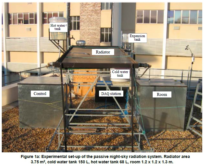
The as-built and tested passive night-sky radiation cooling/heating system considered in this investigation consists of a radiation panel, a cold water storage tank, a hot water storage tank, a room and the interconnecting pipework. The stored cold water can be used to cool a room during the day, particularly in summer. A theoretical time-dependent thermal performance model was also developed and compared with the experimental results and it is shown that the theoretical simulation model captures the experimental system performance to within a reasonable degree of accuracy. A natural circulation experimental set-up was constructed and subsequently used to show that under local (Stellenbosch, South Africa) conditions the typical heat-removal rate from the water in the tank is 55 W/m2 of radiating panel during the night; during the day the water in the hot water-storage tank was heated from 24 °C to 62 °C at a rate of 96 W/m2. The system was also able to cool the room at a rate of 120 W/m3. The results thus confirmed that it is entirely plausible to design an entirely passive system, that is, without the use of any moving mechanical equipment such as pumps and active controls, for both room-cooling and water-heating. It is thus concluded that a passive night-sky radiation cooling/heating system is a viable energy-saving option and that the theoretical simulation, as presented, can be used with confidence as an energy-saving system design and evaluation tool.
HIGHLIGHTS:
• Passively driven renewable energy heating and cooling systems are considered.
• Time-dependent mathematical simulation model is presented.
• Experimental buoyancy-driven heating and cooling system built and tested.
• Experimental results demonstrate the applicability of the theoretical simulation model.
• Saving and evaluation design tool.
Keywords: passive cooling and heating, buoyancy-driven fluid flow, theoretical simulation, experimental verification
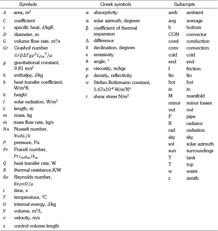
Nomenclature
1. Introduction
Air-conditioning is an energy-greedy operation that is mostly accomplished by the use of vapour compression refrigeration systems (Okoronkwo et al., 2014). The conventional energy sources used in South Africa cause pollution and lead to an increase in environmental air temperatures, which is ascribed to the increased emission of greenhouse gas (GHG) (Winkler, 2007). South Africa is the highest emitter of GHG per person of developing countries. Coal-fired power stations, which provide 93% of South Africa's electricity needs, are largely responsible for the immense emissions, with Sasol's Secunda plant being the largest point source of coal pollution in the world (Botha et al., 2013). Internationally it is accepted that buildings are responsible for 33% of total energy usage. A building consumes far more energy during its productive lifespan to meet demands for heating, cooling and lighting than the energy demanded during its construction (Milford, 2009). Decreasing the demand of energy required for air-conditioning in buildings is, therefore, part of our quest for a more sustainable future. Renewable energy is the key to reducing the current dependency on conventional energy sources (fossil fuels) for energy. Renewable energy resources make use of the natural flow of energy through the earth's ecosystem (Winkler, 2005). Night-sky radiation is one of these natural energy flow phenomena, whereby energy collected by the earth's surface during the day radiates back into the cold night-sky. Night-sky radiation is a sustainable, environmentally friendly natural phenomenon that could be used in the air-conditioning of buildings. At night the sky acts as a heat sink and all objects emit energy through long-wave radiation to the cold sky, causing the objects to cool. Incorporating night-sky radiation and other natural phenomena such as thermosyphoning, where a fluid flows due to a temperature-induced density gradient, a system may be designed for the passive cooling of buildings. In this way the cooling can be achieved without the use of pumps and active controls.
2. Objective
The aim of this paper is to present the finding of a relatively small-scale night-sky radiation system project (Joubert, 2014); this will be done by:
• detailing the design, construction and testing of an experimental night-sky radiation system that has no electrically operated pumps and control devices;
• showing how such a system may be theoretically simulated;
• comparing the theoretical and experimental results with each other and thereby validating the as-developed theoretical model; and
• establishing the thermal performance characteristics of this type of energy-saving system.
3. Literature
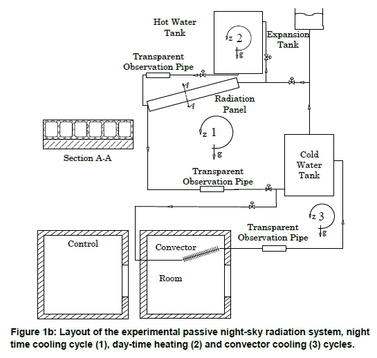
Decreasing the amount of energy consumed by buildings is of utmost importance. By tapping into nature's sustainable resources, energy consumption from fossil fuel can be significantly reduced. One of these sustainable resources is night-sky radiation. Night-sky radiation is a natural phenomenon that occurs at night. An object will radiate energy to the sky, which acts as a heat sink, causing the temperature of the body to decrease. This thermal radiation is also known as long-wave radiation and defined as being electromagnetic radiation of wavelengths 8 to 13 μm and 13.5 to 16 μπι (Wang et al., 2008). The phenomenon is visibly apparent when dew forms on a surface at night. The surface temperature drops below the dew point temperature of the surrounding air and thereby causes the water vapour in the air to condense on the cooled surface. The rate at which an object is cooled by radiation is affected by environmental conditions such as relative humidity, ambient temperature and cloud cover. Consider a natural circulation thermosyphon-type solar water heater, but with two storage tanks, the one tank above the panel and the other below it, as shown in Figures 1a and 1b (and as further described in detail in Section 4). Thermosyphonic flow occurs due to a temperature-induced density gradient. Consider, for instance, a simple, vertically orientated closed looped pipe filled with a working fluid consisting of a hot right-hand side and a cold left-hand side. Temperature differences cause a change in density, the cold left-hand side of the loop being denser than the hot right-hand side. The difference in density causes the pressure (pghcoid) on the cold left hand side to be greater than that of the pressure on the hot right hand side (pghhot). This pressure difference will cause the working fluid to flow around the loop. Systems implementing night-sky radiation and ther-mosyphoning or just night-sky radiation have been investigated over the past three decades. In the studies water-cooled systems are more popular than the air-cooled systems. During such a study Givoni (1977) cooled air in a roof cavity via night-sky radiation. The cooled air was pumped into a thermal storage unit and was recovered when needed. Contrary to cooling air during the night, it is also possible to heat water during the day with some adjustments to the system. More recent studies are those involving the cooling of water via night sky radiation (Meir et al., 2002). Water is stored either in a solar pond or in a storage tank. The solar pond allows the water to thermally radiate the heat extracted from the building, while a storage tank system circulates water through a radiator which radiates the thermal energy extracted from the building to the sky. The radiator panel used for radiation is very similar to that of conventional solar water-heaters, but without their transparent covers. For the design of a night sky radiation system, environmental conditions affecting the performance of the system, such as the ambient temperature, air relative humidity and cloud cover, have a significant effect on the thermal performance of the system.
4. Thermal modelling
The experimental system that was investigated and theoretically modelled is shown in Figure 1. The system essentially consists of three subsystems: a night cooling cycle (1), a day water heating cycle (2) and a day room convector cooling (3), as shown in Figures 1a and 1b. At night the cooling cycle is active, water flows naturally from the cold water storage through to the radiation panel where it is cooled and, thereafter, flows back to the cold water storage. During the day, the heating cycle is active, and the stored cold water flows naturally through the convector situated inside the room. The convector extracts heat from the air in the room causing the water to heat and flow back to the cold water storage. Another cycle during the day is the water-heating cycle in which solar radiation absorbed by the radiation panel during the day heats the water, thereby increasing the overall energy-saving potential of the system.
4.1 Radiator panel
The radiation panel used in this case was a swimming-pool solar water-heater of size 3.0 x 1.25 m = 3.75 m2. It is similar to a conventional solar water-heater except for the absence of glazing and fins. The radiator consists of numerous small channels as depicted by section A-A in Figure 1b. The bottom of the radiation panel is insulated with plywood that also provides structural stiffness. The radiation panel serves as a heat-emitting component at night and as a heat absorber during the day. The placement of the radiation panel is therefore important to ensure that thermosyphoning occurs. The panel should be tilted at an angle equal to the latitude of the experiiment location, and for cooling it should be horizontal, for better heating cycle performance. It was therefore decided to tilt the radiator at only 5° (just enough to ensure a downwards flow through the panel at night and an upwards flow during the day) with an objective to increase the day and night energy savings. The small tilt of the angle has negligible effects on the cooling power of the radiator (Meir et al., 2002).
The amount of energy absorbed by the radiation panel is given by Equation 1.
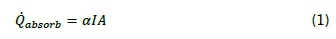
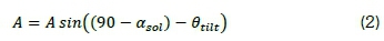
where α is the absorptivity of the radiator, I the direct solar radiation and A the aperture area. The aperture area is influenced by the sun's azimuth angle αCsoi, and the tilt angle Θtm of the radiator. The aperture area is given by Equation 2.
During both the heating and cooling cycles, energy is either gained or lost to the environment by radiation and convection. The heat radiated to the cold sky, acting as a heat sink, is a function of the sky temperature. A colder sky temperature increases the heat transfer rate. The sky temperature can be calculated using the ambient air temperature and relative humidity (Mills, 2009) as expressed by Equation 3.
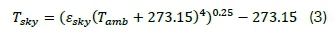
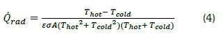
where eskv= 0.741 + 0.00162Tdp at night and eskv = 0.727 + 0.00160Tdp during the day. With the sky temperature known, the heat lost or gained due to radiation can be calculated using Equation 4.
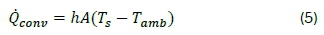
The heat lost or gained by convection is given by Equation 5.
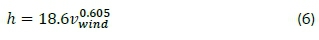
where the convection heat transfer coefficient is a function of the wind speed vwind and is given by (Loveday and Taki, 1996) as expressed by Equation 6.
4.2 Tank and interconnecting pipes
The tank and interconnecting pipes lose or gain heat by convection. The external convection heat transfer coefficients h = Nu k / Dhof the tank and pipes are calculated in terms of a Nusselt number Nu. For wind speeds greater than zero the Nusselt number is calculated (Cengel and Ghajar, 2011) according to Equation 7.
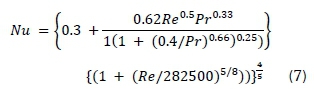
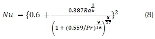
where the Reynolds number Re = pvD/μ. When there is no wind natural convection is assumed and the Nusselt number is calculated by Equation 8.
The internal convection heat transfer coefficient depends on the cross-section of the component. The analysis assumes internal forced convection. The Nusselt number is the average of the constant surface temperature and constant heat transfer rate conditions. Using values suggested by Cengel and Ghajar (2011), the Nusselt number for circular sections is 4.01. The tank was divided into a number of control volumes. Fluid velocity is low and thus de-stratification in the tank is unlikely since natural flow is gravity driven. The variable inlet model, as described by Hollands and Lightstone (1989) was used, which assumes that the water that enters the tank flows either down or up without mixing until it finds the temperature level closest to its inlet temperature and then settles or mixes with the water coinciding with its inlet temperature.
4.3 Natural convector
The convector removes the energy added to the room. The convector is situated in the top section of the room at an angle of 5° to allow natural circulation of the water. Air flows through the convector, is cooled and finds its way to the bottom, allowing new, hotter air to enter the convector. Natural con-vective circulation in the room is, consequently, initiated. The inlet side of the convector is the lowest point and located at 40 mm below the top section of the roof. The convector consists of seven copper tubes with aluminium fins attached to the tubes. The normal conduction resistance for a cylinder, Rcond = ln(ro/r)/2∏Lk, is used for the tubes. The convection resistances for the water side and air side are calculated as Rconu = 1/hA, while the fin resistance includes a fin efficiency η to the equation to get Rfm= 1/ηhA. It is necessary to calculate convection heat transfer coefficients for the water, the base of the tube as well as the fins of the convector. Water heat transfer coefficient is calculated as described in Section 4.2, while the fin heat transfer coefficient is calculated (Mills, 2009) using Equation 9.
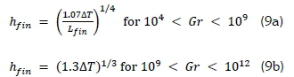
where Gr = ßATgp2Lfin3/μ , and the coefficient of volumetric expansion β, the temperature difference between the fin surface and air ΔΤ and the length Lfmof the fin along which natural convection takes place. It is assumed that the air acts as an ideal gas, which implies that β = 1/Τ, where Τ is in Kelvin.
4.4 Room
The room is subjected to a solar load causing the temperature inside the room to increase. Heat is removed from the air by the cooled water flowing through the convector situated inside the room. A small portion of the heat is lost to the environment and not removed by the convector.
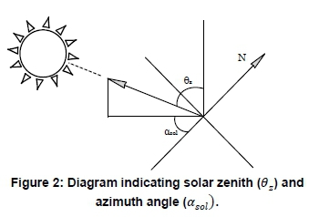
The solar load is affected by the thermal capacity of the room, the solar irradiation, the position of the sun and the outside weather conditions. As the position of the sun changes, the solar load varies due to the change in the incident solar radiation aperture area of the room. At sunrise, for instance, the western side has no solar load, but as the day progresses this load changes, causing the eastern side to have no load, while the western side is subjected to a solar load. The position of the sun has to be known at any point in time to calculate the aperture area. The position of the sun is affected by the day, time of day and location of experiment. The position of the sun is described by two angles, namely the solar azimuth, describing the sun's position measured clockwise from the south, and the zenith, describing the angle of incidence on a horizontal surface, as indicated in Figure 2 (Stine and Geyer, 2001).
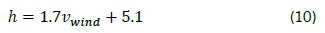
The solar heating load can be calculated using Q = αlA, where I is the direct solar radiation, the aperture area A = WHcosasoi cosθz, and α is the absorptivity of the sheet metal. The steel is very thin and has a high conductivity, so the outside and inside temperatures of the galvanised steel sheet are assumed to be equal. The room is also subjected to convection heat losses on the outside. The convection heat transfer coefficient is a function of windspeed. Loveday and Taki (1996) discussed numerous correlations of wind-speed and heat transfer coefficients on building facades. For the specific case of this study, the seemingly best correlation for a flat surface subjected to varying wind-speeds was found to be given by Equation 10.
5. Transient thermofluid modelling
The method by which the transient performance of a night-sky radiation system, as depicted in Figures 1a and 1b, may be theoretically simulated is presented in this section. The system is divided into three cycles: the night cycle, the hot water cycle and the convector cycle. The physical model representing the system is then discretised into control volumes as shown in Figure 3 (and Figures 8 and 9). The conservation of mass, energy and momentum is then applied to each of the control volumes.
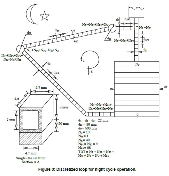
5.1 Night cycle modelling
Consider the discretised loop shown in Figure 3, which consists of a radiator, cold water tank, manifold and pipes. During the night, water circulates naturally through the radiator. The radiator thermally radiates energy to the sky and extracts heat from the water. The water cools, its density increases and under the influence of gravity flows to a lower position and enters the tank. Hotter water from the tank is, in return, pushed into the radiation panel to complete the cycle. The theoretical model requires the application of the conservation of mass, energy and momentum to the indicated control volumes.
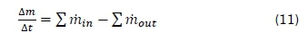
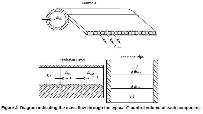
5.2 Conservation of mass
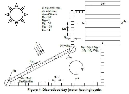
The mass of the control volume for the next time step can be calculated by applying the conservation of mass. The conservation of mass involves the mass flow rate into and out of the control volume. With the mass at the next time step the conservation of energy can be applied to determine the temperature of the control volume for the next time step t + ∆t. Equation 11 shows the application of the general statement of conservation of mass to each ith control volume shown in Figure 4.
Rearranging of Equation 11 gives Equation 12.
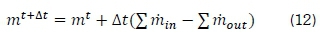
where m = pAzΔz, Az =  and
and 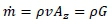 since ν = G / Ax.
5.3 Conservation of energy
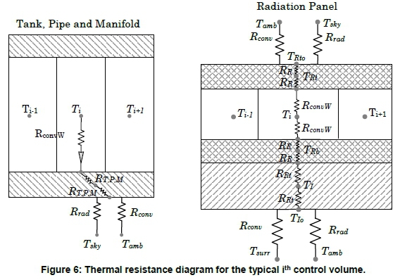
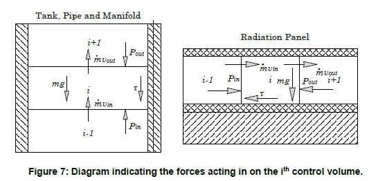
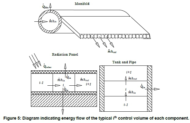
In order to predict the temperature of a control volume each time step, the conservation of energy needs to be applied to the control volume. The conservation of energy considers the flow of energy due to mass flow, conduction, convection and radiation as indicated in Figure 5. With the direction of the flow of energy known, a thermal resistance diagram of the ith control volumes is drawn as shown in Figure 6, and includes the convection, conduction and radiation modes of heat transfer.
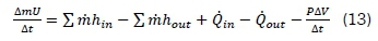
Applying the general statement of conservation of energy to each unique control volume in Figure 3 and ignoring kinetic and potential energy, Equation 13 is obtained.
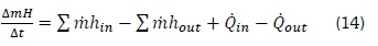
where enthalpy, h = u + PV, therefore, yielding Equation 15.
When enthalpy is expressed as h = cpT, Equation 15 is produced.
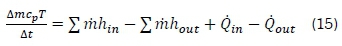
And, with manipulation, Equation 16 is obtained.
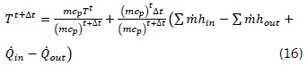
where mt+Δtis given by Equation 12 and cp the specific heat is essentially constant.
5.3 Conservation of momentum
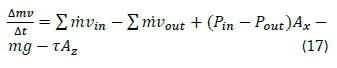
Application of the conservation of momentum to the cycle allows the calculation of the volumetric flow rate at the next time step. The new volumetric flow-rate is used to calculate the mass flow-rate of the control volumes for the next time step. Gravity is only present in the conservation of momentum equation and, therefore, the Boussinesq approximation becomes applicable.
Applying the general statement of the conservation of momentum as in Equation 17 to each control volume shown in Figure 3, and then dividing by Ax = πd2/4 and summing around the loop, the pressure terms cancel out to yield Equation 18.
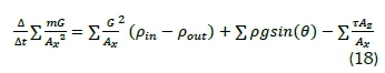
where 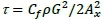 ,
,  and θ =
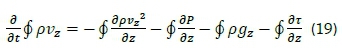
  if the gravity acting against the flow θ is negative and with the flow θ is positive. Dividing by ∆z and in the limit, as ∆z and Ax tend to zero and integrating around the loop Equation 18 becomes Equation 19.
where  or explicitly as in Equation 20.
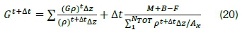
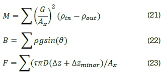
where M, B and F are respectively given by Equations 21, 22 and 23.
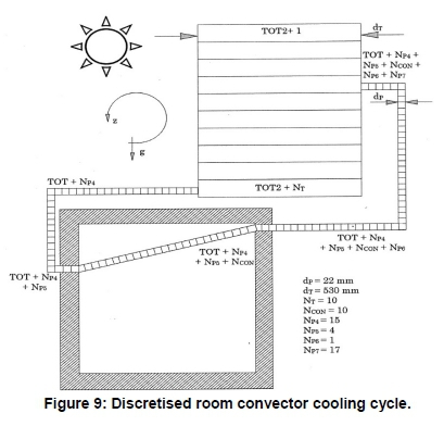
5.4 Day cycle modelling
The thermal and thermofluid modelling procedure as described for the night cycle is equally applicable to both the day water-heating and day room-cooling cycles. Discretised representations of these two cycles are given in Figures 8 and 9, but for the sake of brevity their thermal and thermofluid modelling will not be further described, as they are given by Joubert (2014).
5.4 Numerical solution algorithm
An explicit numerical solution method was used to solve for the set of finite difference equations constituting the thermofluid model. The solution algorithm for the night cooling cycle is given in the supplementary information.
6. Results
Data provided by the weather station of the University of Stellenbosch was used in the theoretical simulation of the system (Stellenbosch-weather, 2014). The theoretical and experimental results are compared with each other to establish the validity and accuracy of the theoretical model solution. The experiment was carried out over an extended period in April 2014. The weather conditions during this period varied from clear to cloudy skies, with most of the days enjoying sunny summer weather. For winter conditions the experiment was carried out only on the night cycle, and this experiment took place during clear sky conditions in June 2014.
6.1 Cold water tank
In Figure 10 the experimental average temperature (of five equally spaced measurements) of the cold water tank is compared with the theoretically determined average (of ten control volumes) cold water tank temperature. The average temperatures vary from a minimum of about 20 °C to a maximum of about 35 °C. It is also seen that the theoretical tank temperatures tended to lag the experimental temperatures, but other than that correspond reasonably well with each other. On the morning of 10 April it is seen that the experimental temperature is not as low as the theoretically predicted value, this being ascribed to the reduction in radiation from the panel to the sky that night due to the presence of cloud coverage, which was not take into account in the theoretical model.
The rate of heat removed from the cold water tank is given by Equation 24.
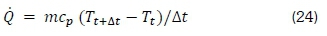
where the mass m = pavgV, pavg is average density water temperature and V is the volume of the cold water tank, which in this case was 150 L. Depending on the weather conditions the heat removal rates from the cold water tank varied between 39 and 75 W/m2, but on average was 55 W/m2. This average value corresponds well with the heat removal rates of 60 W/m2 reported by Dobson (2005) and Okoronkwo et al., (2014).
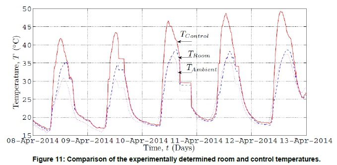
6.2 Room
For comparison a control room was used. The control room had no cooling. The experimentally determined temperatures of the control and room are shown in Figure 11. The cooling system was able to reduce the temperature in the room by between 7 and 12 °C.
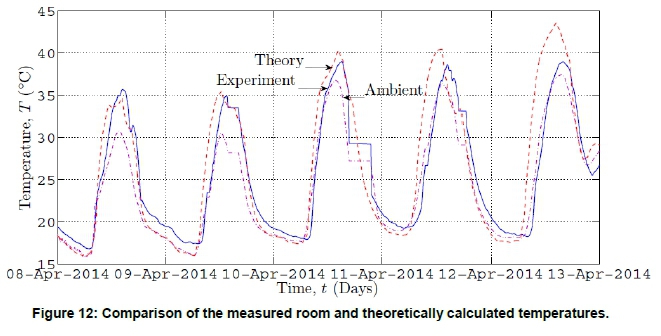
In Figure 12 the theoretically calculated and experimentally measured room temperature are compared. It is seen that the daily temperature profiles closely follow each other. The rate of heat removed from the air in the room by the convector and subsequently absorbed by the water in the cold water tank varied from 102 to 150 W/m3, but on average was 126 W/m3.
6.3 Hot water tank
The theoretically calculated and experimentally measured hot-water storage tank temperatures are shown in Figure 13. Note that the water heated in the panel circulates upwards from the panel to the hot water storage tank only during the day, and stops circulating at night. At night when the water in the panel is cooled and is more dense it now circulates downwards and into the cold water storage tank and the warmer water at the top of the cold water storage tank is displaced upwards and is, in turn, cooled in the panel, and so on. Despite this circulatory flow stopping during the day when the water in the convector in the room is heated by the hot air in the room, its density deceases and it flows upwards and into the cold water storage tank. Subsequently denser cold water in the cold water storage tank, in its turn, now flows downwards and back into the room convector, and so on. Experimental and theoretical temperatures (in Figure 13) compare reasonably with each other. The temperature of the water in the hot water storage (of 68 L) increases by about 30 °C to 40 °C and the rate at which it is heated varies from about 230 to 448 W. On average it is about 96 W/m2 of panel area.
6.4 Winter weather conditions
During typical (but relatively cloudless) winter weather conditions the temperature of the water in the cold water tank is compared with the ambient temperature in Figure 14. Although the water is only cooled to within 5 °C of the now cold ambient temperatures, it was cooled at a rate of 56.6 and 55.8 W/m2 of panel area, for the two days. These values, however, also correspond to the summer panel cooling rates of on average also about 55 W/m2 of panel area.
6.5 Numerical procedural stability
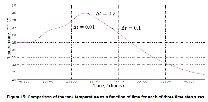
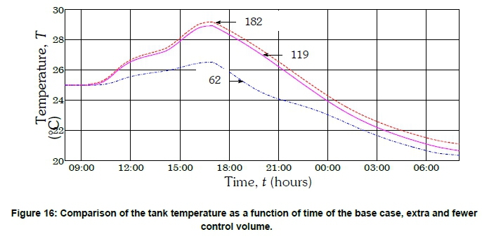
The sensitivity of the size of the control volumes and size of the time steps used in the numerical solution procedure were considered. With a time step of 0.1, it is shown by way of Figure 15 that decreasing the time step further does not significantly influence the tank (for 119 control volume in the tank). Figure 16 shows the effect of keeping the time step at 0.1 s but varying the number of tank control volumes from 62 to 182. It is seen that increasing the number of control volumes to a value greater than 118 does not significantly influence the final tank temperature. It is, therefore, concluded that in the numerical solution a reasonable number of control volumes were used and that the length of the time step used was also reasonable.
7. Discussion and conclusions
The design, construction, experimental testing and theoretical modelling of a night-sky radiation system, comprising of night cooling of water and day time cooling of a room and heating of water, was successful undertaken. The theoretically determined temperatures of the cold water tank, hot water tank and room were graphically compared with the experimentally measured values. The theoretical model used data supplied by the weather station of the University of Stellenbosch, situated close to the experiment location. The theoretical model results compared reasonably well with the experimental results. From a numerical solution procedure point of view, it was also shown that reasonably sized control volumes and time step length were indeed used; this is shown by way of Figures 15 and 16. The theoretical model of the night-time cooling of the water in the cold water-storage tank by the radiating panel yielded results that predict the performance of the system favourably well and this is confirmed by way of Figures 10 to 12. During the night the system was able to radiate energy to the cold sky at a rate of 55 W/m2 of radiating panel. Any cold tank temperature deviations from the experimental results were ascribed to cloud coverage during the night, which was not taken into account by the theoretical model. For the as-sized experimental set-up, during the day, the the air in the room was cooled by the water circulating through the convector at a rate of between between 102 to 150 W/m3, but on average was 126 W/m3 of the room volume. The theoretical model was able to emulate the experimentally measured values as illustrated in Figure 12. Also during the day, the water in the hot water-storage tank was heated at a rate of 96 W/m2 of panel area. Based on the foregoing discussion, it is seen that it is entirely plausible to design and operate a passive system, that is, without the use of any moving mechanical equipment such as pumps and active controls, for water-cooling during the night and room-cooling during the day, as well as for water-heating during the day. It is thus concluded that such a passive cooling/heating system (as illustrated schematically by way of figure 3b) is an entirely viable energy-saving option, and also that the theoretical simulation model, as formulated, can be used with confidence as an energy saving system design and evaluation tool.
Acknowledgements
The authors would like to thank the South African Heat Pipe Association for funding the project.
References
Botha, F., Dobson, R.T. and Harms, T. 2013. Simulation of a syngas from a coal production plant coupled to a high temperature nuclear reactor. Journal of Energy in Southern Africa 24(2): 37-45. [ Links ]
Cengel, Y. and Ghajar, A. 2011. Heat and mass transfer: Fundamentals and applications. Fifth Edition. McGraw-Hill Education. [ Links ]
Dobson, R.T. 2005. Thermal modelling of a night sky radiation cooling system. Journal of Energy in Southern Africa 16(2): 20-31. [ Links ]
Givoni, B. 1977. Solar heating and night radiation cooling by a roof radiation trap. Energy and Buildings 1(2): 141-145. [ Links ]
Hollands, K. and Lightstone, M. 1989. A review of low-flow, stratified-tank solar water heating systems. Solar Energy 43(2): 97-105. [ Links ]
Joubert, G. 2014 Investigation of a passive night-sky radiation system, MSc Eng Thesis, University of Stellenbosch, Stellenbosch, South Africa. [ Links ]
Loveday, D. and Taki, A. 1996. Convective heat transfer coefficients at a plane surface on a full-scale building facade. International Journal of Heat and Mass Transfer 39(8): 1729-1742. [ Links ]
Meir, M., Rekstad, J. and Lovvik, O. 2002. A study of a polymer-based radiative cooling system. Solar Energy 73(6): 403-417. [ Links ]
Milford, R. 2009. Greenhouse gas emission baselines and reduction potentials from buildings in South Africa, UNEP SBCI Sustainable Buildings & Climate Initiative, https://digital.library.unt.edu/ark:/67531/metadc226635/. [ Links ]
Mills, A. 2009. Heat transfer. Pearson Education. [ Links ]
Okoronkwo, C., Nwigwe, K., Ogueke, N., Anyanwu, E., Onyejekwe, D. and Ugwuoke, P. 2014. An experimental investigation of the passive cooling of a building using nighttime radiant cooling. International Journal of Green Energy 11(10): 1072-1083. [ Links ]
Stellenbosch-weather. 2014 August. Available at: http://weather.sun.ac.za/ [ Links ]
Stine, B. and Geyer, M. 2001. Power from the sun, e-book, http://www.powerfromthesun.net/book.html. [ Links ]
Wang, Y., Cui, Y., Zhu, L. and Han, L. 2008. Experiments on novel solar heating and cooling system. Energy Conversion and Management 49(8): 2083-2089. [ Links ]
Winkler, H. 2005. Renewable energy policy in South Africa: Policy options for renewable electricity. Energy Policy 33(1): 27-38. [ Links ]
Winkler, H. 2007. Energy policies for sustainable development in South Africa. Energy for sustainable Development 11(1): 26-34. [ Links ]
* Corresponding author: Tel: +27 (0) 21 808 4268 Email: rtd@sun.ac.za

