


Services on Demand
Article
 English (pdf)
 Article in xml format
 Article references
Indicators

Related links
-
 Cited by Google
 -
 Similars in Google
Share

 Permalink
Journal of Energy in Southern Africa
On-line version ISSN 2413-3051
Print version ISSN 1021-447X
J. energy South. Afr. vol.27 n.1 Cape Town Feb. 2016
RESEARCH ARTICLE
Dynamic model of a small scale concentrating solar cooker with rock bed heat storage
Karidewa NyeingaI, *; Ole J. NydalII; Denis OkelloI; Eldad J.K.B. BandaI
IDepartment of Physics, Makerere University, Kampala, Uganda
IIDepartment of Energy and Process Engineering, Norwegian University of Science & Technology, Trondheim, Norway
ABSTRACT
This study presents a dynamic model for a concentrating solar energy collector with an integrated rock bed heat storage system. The model is based on numerical integration of a set of conservation equations for mass, momentum and energy of the heat carrier, the rock pebbles and the walls. The heat carrier is compressible air. Numerical solutions are implemented based on implicit time integration without iterations. Stability problems at large time steps do not occur but the accuracy is reduced. The model predicts pressure, velocity, density and temperatures of the fluid, rock bed and wall in time and along the bed. The model is validated with experimental results in a laboratory setting on temperature profiles during charging and discharging of rock bed heat storage. The intention is that the model shall serve as a computational tool for upscaling of air based concentrating solar energy systems with rock bed heat storage units.
Keywords: rock bed, heat storage, solar cooker, energy equation, mass balance, momentum equation, pressure equation, staggered grid
1 Introduction
Solar energy storage in the form of thermal energy can contribute significantly to meeting society's desire for clean energy. Thermal energy storage (TES) systems allow for the storage of the excess solar energy that would have been wasted during periods of availability. TES systems can provide continuous energy supply even with varying solar radiation.
The background for this study is the development of a solar cooker with heat storage, which will allow for food preparation after sunset or during periods of bad weather. Lovseth [1] proposed a solar concentrating system with rock bed heat storage for cooking in rural communities. The idea is to store high temperature heat in a packed bed sufficient for cooking and baking. Heetkamp [2] reported the practical aspects and preliminary results on a rock bed storage system designed for cooking based on the initial work by Lovseth [1]. Chikukwa [3] modelled a rock bed storage system using the Schumann model [4] which assumes constant fluid properties. However, at high temperatures, the properties of air change. Okello [5] and Madessa et al. [6] reported on experimental studies on high temperature heat storage using rock beds.
This study presents a computational framework for a dynamic behaviour of a solar concentrating system with a rock bed for heat storage. The dynamics of the system is mainly related to shifting solar intensity on the scale of minutes. The system response has typically two scales: a rapid response at the receiver and slow response at the heat storage. The model framework includes both time scales. Usually, a model is used for time responses of heat storage and then the rest are considered as steady state [7]. The current model can be used for both, by adjusting the time steps. Small time steps will track rapid transients and long time steps can be used for slow time transients. With semi-implicit time integration, stability problems are averted at large time steps. The behaviours of the components are determined from conservation equations. The equations are solved and implemented in vectorized form using a staggered grid without iterations.
2 The mathematical model
2.1 Description of the system
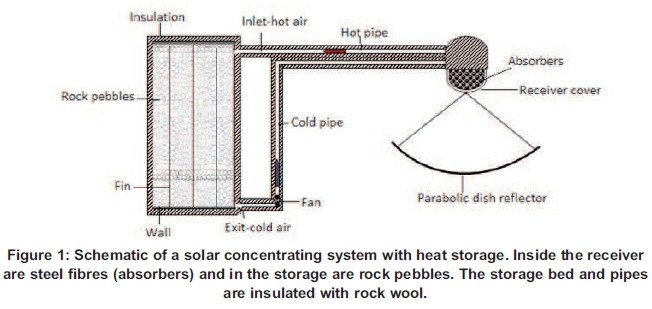
Figure 1 shows the schematic diagram of the solar thermal storage system based on experimental work carried out by Okello [5] and Madessa et al. [6]. It consists of a parabolic dish reflector and a receiver containing fibre absorbers connected to a rock bed storage using pipes. The walls of the pipes and the storage bed are insulated with rock wool. Inside the bed are rock pebbles and aluminium fins are inserted in some of the experiments. A fan at the exit of the bed is used to suck hot air into the bed.
2.2 Conservation equations
The system behaviour is determined from a set of 1D conservation equations for mass, momentum and energy. A system of compressible flows is considered. The behaviour of the fluid is described in terms of properties such as velocity, pressure, density and temperature. Area is included in the conservation equations to account for the change in area from the receiver through the pipes to storage. The system is discretized into numerical sections as shown in Figure 2.
2.3 Equations for fluid (air)
The following equations are written for the gas:
2.3.1 Mass balance
The mass balance can be expressed as Equation 1:
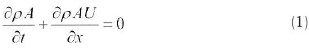
where U is the fluid velocity in the direction of flow, ñ is the fluid density and A is the cross-sectional area for the gas, which depends on the pipe diameter and the volume fraction of the internals (absorber material or rock pebbles).
2.3.2 Momentum equation
The momentum equation is given in Equation 2:
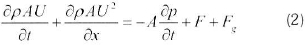
 is the term for pressure force. F is the friction term and written in the form of a standard friction factor (Blasius type or equivalent). An empirical friction factor is employed for the rock bed, as tested by Okello [5]. The Fgis the gravity force (body force). A momentum source in the form of a fan is introduced in the boundary section of the numerical implementation. The momentum equation (Equation 2), together with the mass balance equation (Equation 1) and pressure equation (Equation 3) for compressible flow, is sufficiently general for application also to natural circulation in closed loop systems.
2.3.3 Pressure equation
Pressure is obtained from the mass balance by expanding the density in temperature T and pressure ñ, giving Equation 3:
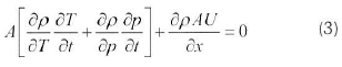
The gas density derivatives are obtained from the state equation (ideal gas for air).
2.3.4 Energy equation
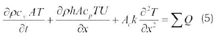
The energy balance, which is applied for air, absorber, rocks and walls is according to Equation 4:
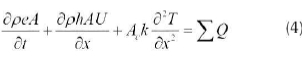
where ∑, Ԛ is the sum of all heat sources and sinks, e is the specific internal energy and h is specific enthalpy. A is the average cross section area and Ack represents the thermal conductivity. For the rock bed, different thermal conductivity models were tested by Okello [5], and a simplified model by Chikukwa [3] was adopted. Expressing the energy equation in terms of heat capacities (cu and cp) and temperature, Equation 4 becomes:
2.4 Walls
The walls of the system are simplified as two layers; a steel part and an outer insulation layer. The steel part is included as the heat capacity of the walls can be large compared with the internal air. The source terms for the wall energy equation are:
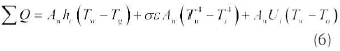
where hc(Tw - Tg) is the convection term (gas-wall) and Uiis the heat transfer coefficient for the insulation to the surrounding. The second term is the net heat exchange by radiation. Tw, Tsand Toare the wall, solid and ambient temperatures respectively.
2.5 Absorbers
The energy balance for an amount of absorber, having the effective area Aain the receiver includes the source terms:
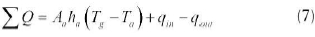
where ha is the heat transfer coefficient between air and the absorber, qinis the concentrated power on the receiver and qoutis the rate of heat loss to the ambient due to radiation similar to the term in (6), while Tgand Taare the gas and absorber temperatures respectively.
2.6 Rock pebbles
The rock pebbles exchange heat with air only:

2.7 Boundary conditions
The following boundary conditions are specified:
-
Constant pressure at the outlet.
-
Flow rate at the inlet with a specific temperature.
-
Ambient temperature outside the pipe and bed.
-
Power source qsun at the absorber.
-
For a closed system, inlet gas temperature in the receiver equals the bed exit temperature of the gas.
2.8 Initial conditions
The following initial conditions are set:
• The pebbles and the absorbers have ambient temperature.
• The wall is at ambient temperature.
• Initial gas temperature is set to ambient temperature.
• Inlet pressure is equal to outside pressure.
2.9 Numerical system
A staggered grid is used to represent the numerical sections for conservation of mass, momentum and energy. Pressure, mass and temperatures are defined for each cell (control volume) and velocities are defined at the cell boundaries. The computational sequence in each time step is:
• Simultaneous solution of volume, momentum and energy equations to give p, U, and T respectively.
• Mass equation to give the conserved mass mg
• State equation gives density pg
The pressure is solved on a non-conservative form, and implicitly in velocities. The masses are solved on conservational form, but implicit in masses. The energy equations are solved implicitly in temperature.
2.10 Error term
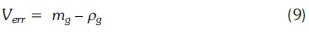
The -mgis from integrated mass and density pgfrom the state equation and integrated pressure from the volume balance. However, since there is no consistency between the two, an error term Verris introduced to take into account the discrepancy, and is expressed as Equation 9:
The aim is to reduce Verrclose to zero and this can be achieved by iteration in each time step until:
To avoid iterations, the error term is implemented as a source term in the pressure equation, which provides for consistency in time. The time step needs to be limited to keep acceptable values for Verr. This scheme is quite robust for increasing time step values.
2.11 Change of area
There is a large area change in the system, in particular from the hot pipe to the heat storage; therefore, a 'reference area' is defined for the velocities. If there were a 'jump' in area, the variables on each side would be defined with (+) and (-). For a given density, the volumetric flow is conserved:
The Aref and Uref are introduced as the reference area and the reference velocity respectively.
Given that Agis the gas flow area, then solving for the gas velocity on the reference area to account for the changing area gives Equation 12:
where Aref is chosen as the cross sectional area of the hot pipe. For mass balance, upstream values in the flux terms are used as shown by Equation 13:
2.12 Discretization
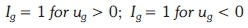
2.12.1 Discretized mass equation Upstream values for mass in the convection terms can be achieved with direction indices, which help in selecting the left, L, and the right, R, side of the cell. The direction indices are:
The discretized mass equation then becomes:
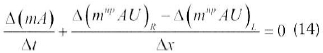
The change in mass of the gas in the section over a time step ∆t is given by Equation 15:
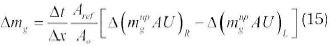
Evaluating the masses at the new time step n+1, the mass equation becomes Equation 16 when written with direction indices:
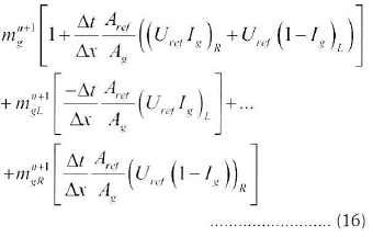
Equation (16) is the discretized mass equation. At the inlet, a mass source G is specified:
The mass equations for the sections are then coupled and the coupling coefficients are extracted. A tri-diagonal matrix equation is then solved.
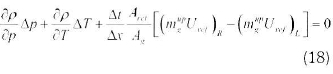
2.12.2 Discretized volume equation The volume balance for a numerical section is similar to that of the mass equation, as in Equation 18:
The convection term is similar to the mass equation, but with a simultaneous solution with velocity now taken implicitly in U as shown in Equation 19:
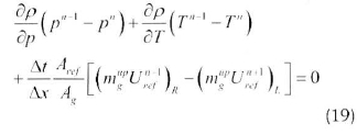
Density ñ is computed from the equation of state.
2.12.3 Discretized momentum equation
From Equation (2), the discretized momentum equation can be expressed as Equation 20:
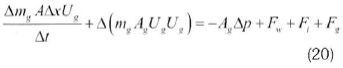
where the mgUgUgis the convection of momentum term; Fwand Fiare the friction terms due to the wall and internals (stone pebbles and absorbers) respectively, while Fgis the gravity term.
The mass, friction and gravity terms are split into two parts, representing the half cells of each side of the boundary. The sides are denoted with '+' and '-'
2.12.4 Discretized energy equation The discretized energy equation can be written similarly as for the mass equation, as in Equation 21:
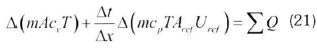
The convection terms are taken as implicit in temperatures rather than in velocities.
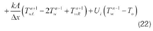
2.12.5 Discretized wall energy equation
The discretized wall energy is represented by
Equation 22:
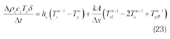
2.12.6 Discretized solids energy equation The discretized energy equation for the internals (stone or absorber) is expressed according to Equation 23:
2.13 Matrix assembly
A staggered grid is used. The boundary sections contain boundary pressures and velocities, which are solved at the boundaries. The inlet is closed (no boundary fluxes) and the source is specified in section 2 (first pipe section).
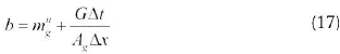
From each equation, coefficients are extracted and a set of equations in the form of Equation 24 are solved:
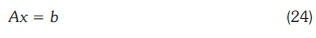
where A is the coefficient matrix, x is the vector of variables and b is a vector of constants. With simultaneous and implicit solution of the conservation equations, one builds matrices and inverts them. The matrices are band matrices and the band vectors are computed and vectorized in MATLAB. Looping over all sections is avoided. The computational sequence is to generate the coefficient diagonals for each equation and then put them in the right order into the matrix.
3 Results and discussion
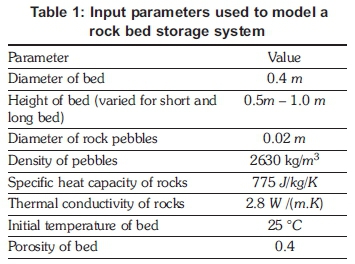
Table 1 gives a summary of the initial input parameters used in the model for the storage system.
3.1 Charging of a rock bed thermal storage system
Inlet air at ambient temperature of 25 °C was heated in a solar concentrating system to a constant temperature of 350 °C and sucked into rock bed storage of height 0.5 m containing spherical rock pebbles. The mass flow rate of the air was maintained at 0.007 kg/s during charging of the bed. Figure 3 shows the predicted temperature profiles in the bed during charging for five 5 hours. The top of the bed attained high temperatures close to 350 °C. At the bottom of the bed, low temperatures are observed, meaning this part of the bed is not yet charged. The temperature of the lower bed is also observed to increase with charging time. During charging, the hot air loses energy to the pebbles as it flows down the bed from the top. As charging continues, the hot air reaches the mid and the bottom parts of the bed and hence the observed temperature front passing through the bed. At the end of the five 5 hour charging period, the temperature at the bottom rises above the ambient temperature. The temperature gradient between the top and the bottom gradually disappears as charging progresses. During charging of the bed, the main heat transfer process is convection especially at low temperatures while the contribution by radiation heat transfer increases at high temperatures [8]. As discussed by several other authors ([3],[8],[9]) the mass flow rate of the air affects the rate of charging of the bed. The model temperature profiles in the storage bed during charging, shown in Figure 3, are in very close agreement with similar results obtained by other researchers ([3],[8],[9]).
3.2 Experimental validation
The model was validated using experimental data measured during thermal degradation of a rock bed by Okello [5]. Validation of the effective rock bed thermal conductivity was made using the degradation data. A no-flow condition lead constituted a pure heat conduction problem. The validated conductivity model was then used in the simulations of the charging of the bed and the results compared with the experiments.
3.2.1 Validation of the model with experimental thermal degradation results
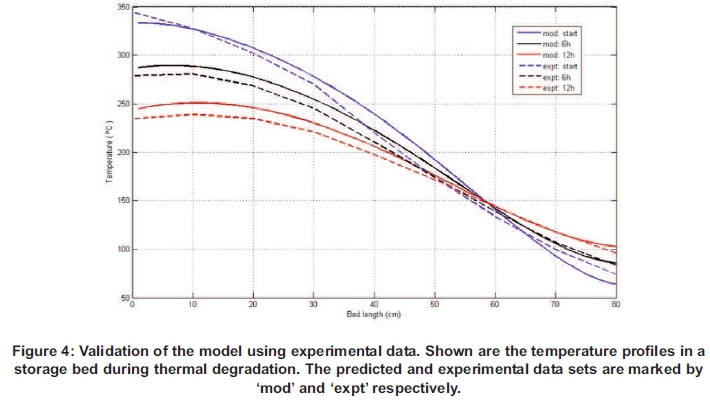
In the experimental set up, a rock bed storage of height 1 m was charged for three 3 hours. The temperature of the bed was recorded during the thermal degradation process for twelve 12 hours, see [5] for details of the experiment. Figure 4 shows the model predicted and the measured temperature profiles in the bed during the thermal degradation. The temperature profiles in the top and middle sections of the bed were observed to decrease over time while that at the bottom increases. The fall in temperature at the top is faster compared with the gain at the bottom. After twelve 12 hours, the temperature at the top fell by more than 100 °C. The predicted outcome was somehow above measurements, mainly due to losses in the experiment, which were not accurately estimated in the model.
In general, the model predictions are in close agreement with experimental results despite deviations at the bottom of the bed. During the degradation process, it was observed that there were higher heat losses at the top and bottom of the bed compared with the sides. Therefore, U-values in the order of ~1.4 W/m2K were used at the top of the bed, indicating poor insulation. The profiles shown in this figure clearly present high heat losses at the start of low temperature at the bottom of the bed (010 cm ). See portions of the curves between bed lengths (0-10 cm). The slight discrepancies observed between the model and the experimental data were likely associated with the variance in rock sizes, porosity and presence of sand in the set-up.
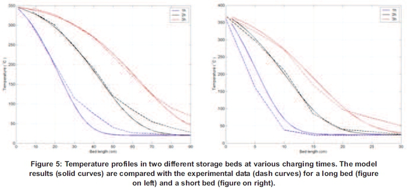
3.2.2 Charging of a rock bed: Comparison of model results with experimental data The validated conductivity model was used in charging simulations and the predicted performance compared with measurements. The experiments were discussed by Okello [5] and Madessa et al. [6] for long bed (height = 1.0 m) and short bed (height = 0.5 m) respectively. Figure 5 shows the temperature profiles in the bed during charging for predicted and measured data. As expected, the temperature of the bed increased with charging time when the top of the bed attained temperatures close to the inlet air temperature, while the bottom of the bed showed that the temperature remained close to ambient. In both cases, the predicted results are very close to the measurements especially at the top and middle parts of the bed, accompanied by some deviation at the bottom of beds where the model predictions were relatively low.
The main cause for the discrepancy at the bottom was attributed to pebble sizes not being uniform in the experiment and the presence of sand particles, which all influenced the charging process of a bed. Particle size and shape affected the distribution of the bed porosity. Irregular shapes lead to a much more inhomogeneous distribution of the bed porosity than spherical particles [10] and resulted in non-uniform flow of the fluid as it approached the bottom of the bed [11]. Measurement uncertainties may also contribute to the observed discrepancies. Difficulties associated with experimental measurements possibly added to the culprits for observed discrepancies..
4 Conclusions
A dynamic model for solar thermal storage system at high temperature was developed. The model was based on numerical integration of a set of conservation equations for mass, momentum and energy of the heat carrier, the rock pebbles and the walls. A system of compressible flows was treated. Semi-implicit time integration was used. Stability problems at large time steps did not occur. The equations were solved and implemented in vectorized form in a staggered grid without any iteration. The model predicted pressure, air velocity, air density and temperatures of the air, rock bed and wall in time and along the container. Validation of the model with experiments was performed. Comparison between predicted and experimental results during charging of the bed showed a good agreement with minor discrepancies at the bottom of the bed. The numerical scheme formulated in this study is quite general and is likely applicable to any storage medium and fluid type, with minor modifications. This model gives strong promise of being able to serve as a guide in the develop[ment and construction of solar oven systems, facilitated by additional work to improve the derivation and validation of the model.
Acknowledgements
The authors thank the Norwegian Agency for Development Cooperation for financial support, and ack-owledge participating in a network project between African universities on concentrating solar energy systems.
References
1. Lovseth J. Small, multi-purpose concentrating solar energy systems for villages. Proceedings ISES 1997 Solar World Congress, 7:108-177, 1997. [ Links ]
2. Heetkamp van den R.R.J. The development of small solar concentrating systems with heat storage for rural food preparation. Physica Scripta T97, pages 99-106, 2002. [ Links ]
3. Chikukwa A. Modelling of a Solar Stove: Small concentrating system with a heat storage. PhD thesis, Norwegian University of Science & Technology. 2007. [ Links ]
4. Schumann T.E.W. A liquid flowing through a porous prism. J. Franklin Inst., 208:405, 1929. [ Links ]
5. Okello D. Rock bed thermal energy storage for solar cooking application - potential for solar cooking in Uganda. PhD thesis, Makerere University, 2012. [ Links ]
6. Madessa H.B., Lovesth J., and Nydal O.J. Experimental investigation on rock bed for high temperature solar thermal storage. In Renewable Energy Shaping Our Future - Proceedings of the ISES Solar World Congress 2009. Johannesburg, South Africa, 11-14 October, 2009. [ Links ]
7. Versteeg H.K. and Malalasekera W. An Introduction to Computational Fluid Dynamics. Addis on Wesley Longman Limited, 1995. [ Links ]
8. Dufie J.A. and Beckman W.A. Solar Engineering of Thermal Processes. John Wiley and Sons,Inc. 2nd edition, 2006. [ Links ]
9. Anton Meir, Christian Winkler, and Daniel Wuillemin. Experiment for modeling high temperature rock bed storage. Solar Energy Materials, 24:255-264, 1991. [ Links ]
10. Elisabeth Schroder, Andreas Class, and Lambert Krebs. Measurements of heat transfer between particles and gas in packed beds at low to medium Reynolds numbers. Experimental Thermal and Fluid Science, 30:545-558, 2006. [ Links ]
11. Bhavsar V.C and Balakrishna A. R. Pebble bed-oil thermal energy storage for solar thermo-electric power systems. International journal of energy research, 14:233-240, 1990. [ Links ]
12. Slavin A.J., Arcas V., Greenhalgh C.A., Irvin E.R., and Marshall D.B. Theoretical model for the thermal conductivity of a packed bed of solid spheroids in the presence of a static gas, with no adjustable parameters except at low pressure and temperature. International Journal of Heat and Mass Transfer, 45:4151-4161, 2002. [ Links ]
13. Barrie W. Jones and Mahyar Golshekan. Destratification and other properties of a packed bed heat store. J. Heat and Mass Transfer, 32:351-359, 1989. [ Links ]
* Corresponding author: Email: karidewa@yahoo.com
Tel: +256790550422

