


Servicios Personalizados
Articulo
 Inglés (pdf)
 Articulo en XML
 Referencias del artículo
Indicadores

Links relacionados
-
 Citado por Google
 -
 Similares en Google
Compartir

 Permalink
Journal of Energy in Southern Africa
versión On-line ISSN 2413-3051
versión impresa ISSN 1021-447X
J. energy South. Afr. vol.26 no.3 Cape Town ago. 2015
CONFERENCE PAPER
Efficiency analysis of an induction motor with direct torque and flux control at a hot rolling mill
Rupert Gouws
Faculty of Engineering, North-West University, Potchefstroom, South Africa
ABSTRACT
This paper presents an efficiency analysis of an induction motor with direct torque and flux control at a hot rolling mill in South Africa. Two scenarios were evaluated: 1) where the induction motor was controlled at a constant speed with a variable thickness slab; and 2) where the speed of the induction motor was controlled according to the thickness of the slab. Both scenarios used the speed as reference to control the torque and flux of the induction motor. A comparison on the energy consumption of the induction motor for both scenarios was done by means of a detailed simulation model. The simulation model for this specific case study is explained in detail. The results obtained showed an increase in the efficiency of the induction motor from the original system (scenario 1) to the improved system (scenario 2). Part of this paper provides an overview on hot rolling mills.
Keywords: efficiency analysis; induction motor; hot rolling mill; direct torque control; flux control
1. Introduction
In this paper, the efficiency analysis of an induction motor with direct torque and flux control at a hot rolling mill in South Africa is presented.
The energy consumption of the induction motor is calculated and compared by means of a simulation model for the following two scenarios: 1) where the speed is kept constant with a variable thickness slab and 2) where the speed is controlled according to the thickness of the slab. Section 4 provides more detail on the results obtained from the simulation model for this specific case study.
A hot rolling mill plant near Witbank in Mpumalanga, South Africa, was investigated as a case study. The hot rolling mill plant has an installed capacity to produce 4000 MT of steel bars in a month. The monthly average production is currently 3400 MT (85% of the installed capacity).
The diameter of the bars being produced varies from 8 mm to 20 mm. The demand of the plant is 1000 KVA and the daily energy consumption is 10 MWh. The parameters and specifications of the hot rolling mill plant were used in the design process of the simulation model. Section 3 provides more detail on the simulation case study.
This paper provides an overview of hot rolling mills, a simulation case study where the specifications and parameters of the hot rolling mill plant near Witbank has been incorporated, results on the different scenarios and a conclusion on the results.
When metal is passed through a pair of rolls, it is termed rolling. Hot rolling occurs when the temperature of the metal is above the recrystallization temperature and cold rolling occurs when the temperature of the metal is below the recrystallization temperature (Degarmo, et al., 2003; Roberts, 1983).
2. Overview on hot rolling mills
Figure 1 provides a diagram of a four-high hot rolling mill stand. This rolling mill is also known as a reduction mill. A slab is passed through two work rollers which reduces the thickness of the slab. The reduction in thickness is caused by a high compression force applied by hydraulic rams. The reduction in strip thickness causes a temperature rise at the roll gap, which is cooled by air and a lubricant solution (Pittner, et al., 2011).
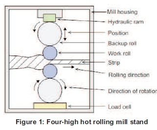
Hot rolling mills are usually equipped with sensors to measure the roll force at each stand, strip tension force, strip thickness, work roll speed, roll gap actuator (hydraulic ram) position and strip speed. The backup rolls are installed to provide rigid support to the working rolls and to prevent bending under rolling load (Pittner, et al., 2011).
Figure 2 provides an overview diagram of the hot strip/rolling production process. After the refining and alloying processes (slab casting process), the molten metal is cast into semi-continuous casters of 10 - 25 Ton slabs (Achenbach, 2002).
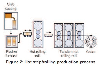
The slabs are then pre-heated in the pusher furnace and hot rolled by a single-stand hot rolling mill. The slabs are then passed through a tandem hot rolling mill, which provides strips with a thickness of 2.5 - 6 mm. The strips can then be coiled at a temperature of approximately 300oC (Achenbach, 2002). Schroder provides more detail on the mechanics of rolling mills (Schroder, 2011).
3. Simulation case study
This section provides the design of the simulation model from the specifications and parameters of the hot rolling mill plant.
Table 1 provides the parameters of the hot rolling mill. These parameters together with an adapted model of Blanchette, et al., (2007) were used in the design process of the simulation model for this specific case study.
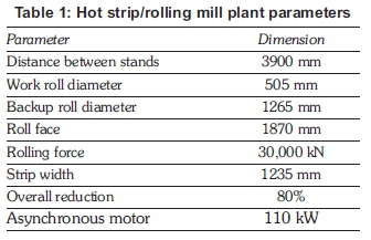
Figure 3 provides an overview of the control process for this specific case study. From the figure, it can be seen that a three-phase diode rectifier supplies a braking chopper. The braking chopper is a dynamic braking chopper with a DC bus capacitor which absorbs the energy produced when the motor decelerates.
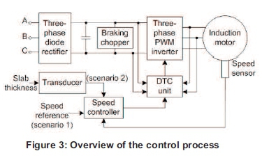
The output of the braking chopper is connected to a three-phase PWM voltage source inverter which supplies the induction motor. A speed controller uses the speed of the induction motor (measured by means of a speed sensor). The speed controller uses a PI controller to produce flux and torque references for the DTC unit. The thickness of the slab is measured by means of a position sensor. A transducer converts this signal to a reference speed.
The torque and flux are calculated in the DTC unit and compared to their respective references. An optimal switching table is then used to generate the inverter switching pulses.
For scenario 1, the speed reference is kept constant and a variable thickness slab is selected. For scenario 2, the speed is controlled according to the thickness of the slab. More detail on the control of steel rolling mills is available at Pedersen, et al. (1998), Sbarbaro-Hofer, et al., (1992) and Ashok (2010).
For the simulation model design as shown in Figure 4, an AC4 block from the SimPower-Systems™ library was used. The block models the direct torque control (DTC) induction motor drive with the braking chopper for the motor. A 110 kW induction motor (see Table 1 for the plant parameters) was used for this simulation.
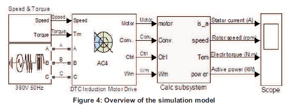
The three-phase diode rectifier, braking chopper, three-phase PWM inverter, DTC unit and speed controller is simulated by means of the AC4 block. The AC4 block was adapted to incorporate the dynamics and parameters of this specific case study.
The speed and torque characteristics for the two scenarios are simulated by means of the speed & torque subsystem. Bose provides more detail on modern power electronics and AC drives (Bose, 2002).
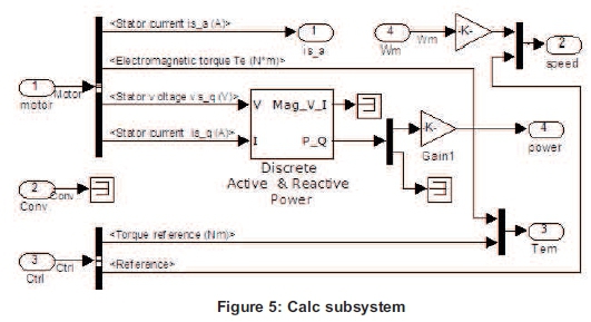
Figure 5 provides the calc subsystem. This subsystem performs the calculations for the stator current, speed, electromagnetic torque and power. Grelet, et al., 1997 and Krause, 1986 provides more detail on the analysis of electric machinery.
4. Results
This section provides the results of the simulation model for this specific case study. The results are divided into the following three sections: 1) scenario 1 (speed is kept constant with a variable thickness slab); 2) scenario 2 (speed is controlled according to the thickness of the slab); and 3) combined results (a comparison between the results of scenario 1 and scenario 2).
4.1 Scenario 1
In this scenario, the speed is constantly controlled at 150 rpm and a variable thickness slab is selected. In this scenario, the rotor is given 10 s to start-up before a slab is processed. Figure 6 shows the stator current, rotor speed and electromagnetic torque for this scenario.
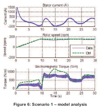
The stator current peaks around 1500 A during start-up. The rotor speed dips the moment the slab enters the process. The actual speed (Data) then closely follows the control speed (Ctrl). The actual electromagnetic torque (Data) closely follows the control torque (Ctrl).
4.2 Scenario 2
In this scenario, the speed is controlled according to the thickness of the slab. The same variable thickness slab is selected for both scenarios. In this scenario, the rotor is again given 10 s to start-up before a slab is processed. Figure 7 shows the stator current, rotor speed and electromagnetic torque for scenario 2.
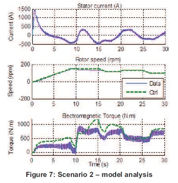
The stator current again peaks around 1500 A during start-up and the rotor speed dips the moment the slab enters the process, but the speed is now controlled according to the thickness of the slab. The actual speed (Data) closely follows the control speed (Ctrl). The actual electromagnetic torque (Data) closely follows the control torque (Ctrl).
4.3 Combined results
In this section, the active power for the two scenarios is evaluated. Figure 8 shows the active power and cumulative active power for scenario 1 and scenario 2. A lot of spikes are visible on the active power signals, and this is caused by the switching of the three-phase PMW voltage source inverter.
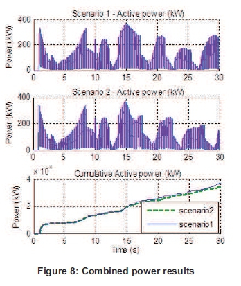
The result of the first 10 s for both scenarios is the same, since this is the start-up time of the rotor. Thereafter, different profiles can be seen. From the cumulative active power graph it can be seen that the cumulative power after 30 s for scenario 2 is less than that of scenario 1. The cumulative energy consumption resulted to an average improvement of 4.44% from scenario 1 to scenario 2.
5. Conclusion
In this paper, an efficiency analysis of an induction motor with direct torque and flux control at a hot rolling mill near Witbank(in Mpumalanga, South Africa, was done. The following two scenarios were evaluated: 1) where the speed is constantly controlled with a variable thickness slab; and 2) where the speed is controlled according to the thickness of the slab.
A simulation model was designed in Matlab® Simulink® in order to obtain results and evaluate the two scenarios. The specifications and parameters of the physical system were used in the design process of the simulation model.
From the combined results of the two scenarios, it can be seen that the cumulative power for scenario 1 is higher than that of scenario 2. The cumulative energy consumption resulted to an average improvement of 4.44% from scenario 1 to scenario 2.
References
Achenbach Buschhutten. (2002). Aluminium Rolling Mill Technology, Die bibliothek der technik, 233. [ Links ]
Ashok S. (2010). PLC-Based Load Management in Steel Rolling Mills, Energy Engineering, 107(4). [ Links ]
Blanchette H. and Dessaint L.A. (2007). AC4 - DTC Induction 200 HP Motor Drive, Ecole de Technology Superieure, Montreal. [ Links ]
Bose B.K. (2002). Modern Power Electronics and AC Drives, Prentice-Hall, New York, 2002. [ Links ]
Degarmo E.P, Black J.T., and Kohser R.A. (2003). Materials and Processes in Manufacturing - 9th edition, Wiley, ISBN 0-471-65653-4. [ Links ]
Grelet G. and Clerc G. (1997). Actionneurs électriques, Editions Eyrolles, Paris. [ Links ]
Krause PC. (1986) Analysis of Electric Machinery, McGraw-Hill. [ Links ]
Pedersen L.M. and Wittenmark B. (1998). Multivariable Controller Design for a Hot Rolling Mill, IEEE Transactions on Control System Technology, 6(2). [ Links ]
Pittner J. and Simaan M.A. (2011). Tandem Cold Metal Trolling Mill Control - Using Practical Advanced Methods, Springer-Verlag, London. [ Links ]
Roberts W.L. (1983). Hot Rolling of Steel, CRC Press, ISBN 9780824713454. [ Links ]
Sbarbaro-Hofer D., Neumerkel D., and Hunt K. (1992). Neural Control of a Steel Rolling Mill, IEEE International Symposium on Intelligent Control. Schroder K.H. (2011). A Basic Understanding of the Mechanics of Rolling Mill Rolls, www.est.co.at. [ Links ]
Paper presented at the Industrial & Commercial Use of Energy Conference (ICUE) 2014, 18 - 20 August 2014, Cape Town, South Africa. Rublished here with permission. Not peer-reviewed for JESA

