


Services on Demand
Article
 English (pdf)
 Article in xml format
 Article references
Indicators

Related links
-
 Cited by Google
 -
 Similars in Google
Share

 Permalink
Journal of Energy in Southern Africa
On-line version ISSN 2413-3051
Print version ISSN 1021-447X
J. energy South. Afr. vol.25 n.4 Cape Town Nov. 2014
Improving stability of utility-tied wind generators using dynamic voltage restorer
G Sivasankar; V Suresh Kumar
Electrical Engineering Department, Thiagarajar College of Engineering, Tiruparamkundaram, Madurai, TamilNadu, India
ABSTRACT
The generation of electricity using wind power is significantly increasing and has received considerable attention in recent years. One important problem with the induction generator based wind farms is that they are vulnerable to voltage disturbances and short circuit faults. Any such disturbance may cause wind farm outages. Since wind power contribution is in considerable percentage, such outages may lead to power system stability issues and also violate the grid code requirements. Thus, improving the reliability of wind farms is essential to maintain the stability of the system. The proposed strategy is to use Dynamic Voltage Restorer (DVR), which is one of the promising devices to compensate the voltage disturbance and to improve the stability of the system. It provides the wind generator with the fault ride through capability and improves the reliability of the system. Extensive simulation results are included to illustrate the operation of DVR and fault compensation.
Keywords: wind power generation, power system faults, fault detection, voltage control, and stability
1. Introduction
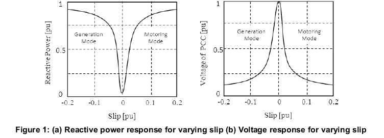
In recent years, wind power generation is in rapid expansion and its contribution to the power sector has been increasing day by day. This situation has forced the need for evaluation of their impact on power system dynamics. During short circuit fault or severe load variation, voltage sags are observed in the network. They are characterised by a sudden reduction in voltage and phase jump. The induction generators are not able to withstand such low voltages due to reactive power needed to restore the internal magnetic flux, once the fault is cleared (Milanovic, 2007). Figure1 shows the variation of the voltage and reactive power absorbed by the induction generator with slip. It can be seen from the figure that as the slip or the power increases, the amount of reactive power absorbed by the generator also increases. Due to the large amount of reactive power drawn from the network, the voltage across the transmission line drops. The voltage at the point of connection with the network decreases, as the slip increases. The voltage recovery after disturbance is hindered by the consumption of reactive power. This behaviour limits the fault ride through capability. Hence, wind farms are disconnected during fault for safety. In the past, the wind power penetration was low in percentage and hence, any outage might have not affected the system stability. But now these days, wind generation is in rapid expansion and its contribution to the grid is as conventional generation plants as stated by Bollen (2005). Hence, any outage of wind plant may lead to power swing and collapse the stability.
In this paper, the issues related to stability of Fixed Speed Induction Generators (FSIG) based wind farms are analysed. The wind farms are operated in two modes, one as grid integrated mode and the other as standalone mode. When a wind system is inactive, the grid supplies electricity to the consumers. When surplus electricity is produced by wind farms, it meets the local demand and the remaining power is fed to the grid. The utility employs a billing system known as net metering. Net metering is a system in which the electric bill is based on net consumption minus production. The electric billing is based on the amount of utility energy consumed minus the amount of energy provided to the grid from a renewable energy system. A safety disconnect switch is available near the point of connection, which enables service personnel to disconnect wind farms from the grid during fault condition and to be operated as a standalone system.
Hence, a wind farm serves consumers as stand-alone mode. In both modes, the wind generator suffers with stability problems by grid faults or load disturbances. Hence, the distributed generation system focuses on power quality improvement (Singh, 2011). Several schemes are under research for protection and power quality improvement (Siozinys, 2012; Vaimann, 2012). Grid tied active filters are usually designed for performance improvement (Biricik, 2013).
The proposed strategy is to use dynamic voltage restorer DVR for voltage sag compensation by series voltage injection as shown in Figure 2. DVR is a power electronic controller that can protect the wind farm from disturbances without loss of stability and guarantee the reliability of the system. The proposed DVR can also limit the fault current and protect the DG from over current due to voltage disturbance.
2. Series voltage compensation
The most commonly encountered problem in the system is voltage dip. Voltage sags are mainly caused by short duration faults in the supply line (Bollen, 1999). Hence, mitigation of sag can only be a complete solution for the aforementioned problems. The use of DVR is an appropriate solution for sag and its related issues (Al-Hadidi, 2008; Meyer and De Doncker, 2008; Nielsen, 2004). The compensation is accomplished by insertion of a voltage equal to the sag depth with appropriate phase angle in series with the line (Ryckaert, 2008; Awad, 2004). An equivalent circuit representation of a series voltage compensation scheme is illustrated in Figure 3.
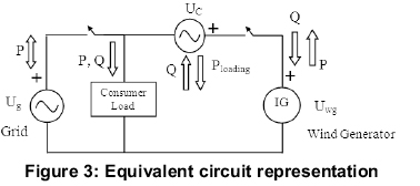
The grid voltage source, the wind generator voltage source, consumer load and Series compensation source are integrated with two safety switches. The voltage dip mitigation is done by insertion of compensation voltage in series with the line. The steps involved in series compensator for mitigation as follows:
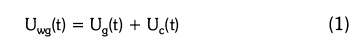
The imbalance at the wind generator terminal is to be cancelled by the compensating voltage to obtain balanced voltages at terminals. Therefore,

The positive-sequence voltage magnitude of the wind generator Uwg should be set to the desired regulated voltage. A compensator is a positive-sequence voltage (I Uc+| ) injected in series. Since the grid current flows through the series compensator the must have a phase difference of 90o with ig+. This results in:
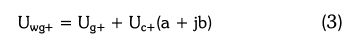
where (a + jb) is the unit vector. It is perpendicular to Ig+. Assuming Uwg+ = Uwg+  . Eq. 3 results in second-order equation:
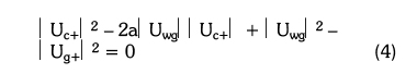
When the desired regulated voltage Uwg is achieved, the Eq. 4 will result in two real solutions for |Uc+|. The minimum solution is chosen for smaller rating of the DVR.
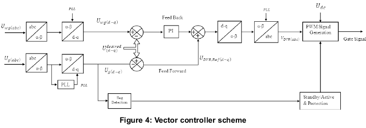
3. Control of the DVR
The control of DVR is done using a high performance vector controller (Ottersten, 2012). The vector controller scheme is illustrated as shown in Figure. 4. This control scheme of the DVR includes: reference voltage generation, control of injection voltage and protection of DVR.
3.1 Reference voltage generation
The controller has to generate an accurate reference voltage for successful compensation. The Software Phase Locked Loop (SPLL) circuit is preferred for synchronization of the system (Awad, 2005). The advantages of this thod are frequency
adaptive performance, high filtering capability and relatively low computational burden. SPLL provides a successful solution for voltage distorted and frequency varying conditions. Figure 5 illustrates the structure of the SPLL, in which Ug(abc) is the input voltage, ωd and θd (=ωdt + Φ are the estimated frequency and angle, respectively. ωff is the nominal frequency. The input voltage is transformed to Ua and Uα coordinates which are inphase and quadrature-phase components, respectively.
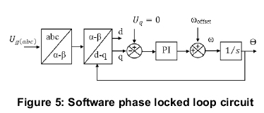
The Park (dq0) transformation is used, which is applied for a time-dependent arbitrary three-phase system. It is used to decouple variables and to refer a common reference frame. The grid voltage may contain negative and zero-sequence components due to unbalanced voltage. Hence, the system voltage is transformed into the synchronous dq0 reference frame. For an unbalanced voltage, the Park transformation results in:
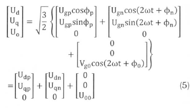
In equation 5 Ud yields an estimation of the input voltage amplitude and gives the phase error information. The output signal Uq of the Phase Detector (PD) is passed through the Loop Filter LF to attenuate the high-frequency signals. The nominal value of the fundamental frequency ωffis then added to the output of LF to accelerate the initial lock-in process. This reduces the control effort. The resulting signal ωdis integrated and the estimated angle is obtained. Then, the vector controller calculates the values of grid voltage Ug and wind generator voltage Uwg in d-q coordinates as Ug(d-q) and Uwg(d-q). According to Eq. 5, the dc components (UgpcosΦp and UgpsinΦp) are obtained from the positive sequence component of the dq0 reference frame. Then, the Udpis maintained at maximum magnitude UM and all other components are eliminated using the compensation voltage. As a result, the reference voltage is obtained as shown as:
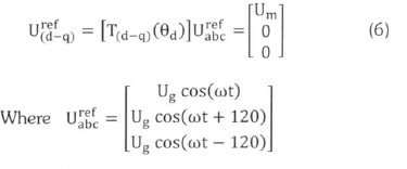
The voltage sag detection is carried out by comparing the grid voltage with the reference voltage. The DVR reference voltage  is generated
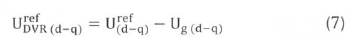
The , reference voltage of Eq. 7 is then inversely transformed into the abc reference frame.
3.2 Control of injection voltage
The control of injection voltage is done by the combination of grid voltage feed-forward and wind generator voltage feedback. The compensation voltage generated in the inverter and the voltage actually injected in series with the line are equalized using a PI regulator as a feedback control. The regulator output is added to DVR reference, which serves as feed forward to improve the system response speed. The dc-link voltage is used to calculate the required modulation depth to inject the difference between grid voltage and the reference voltage. Finally, a Sinusoidal Pulse Width Modulation (SPWM) is used to produce inverter switching signals.
3.3 Real and reactive power exchange
The fault ride through capability of the wind generator is not only affected by voltage disturbance but also by power dearth. The proposed DVR is capable of providing real and reactive power support. The uncontrolled shunt rectifiers are used to maintain a strong dc link which acts as a source to meet the real power demand. The reactive power compensation is done by switching the series converter in an appropriate phase angle
3.4 DVR protection system
The series connected DVR inverter may face severe problem due to transients or fault current in the grid. Further, there is a chance of high in-rush of current reflection in to DVR, if the sag is not completely compensated. A proper protection of DVR inverter is one of the important aspects of the design, which can be done using the design scheme presented in (Newman, 2002).
3.5 Design and ratings of the proposed system
The DVR is capable of protecting wind generators from 100% voltage dips. The limitation of this compensation is that the diode rectifier and passive filter elements increase the cost of installation.
The average voltage across the DC link is calculated as follows:

where Umis maximum of the rated voltage  .
.
The energy stored in the capacitor is derived as:
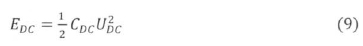
where CDC is the dc link capacitor.
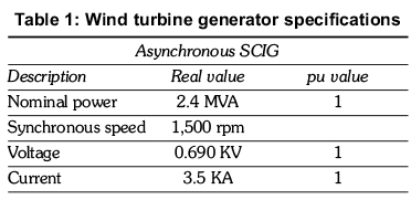
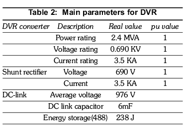
The WTGs specifications are tabulated in Table 1. The design parameters of DVR are presented in Table 2.
4. Simulation results and discussion
4.1 Grid connected FSIG
Case 1
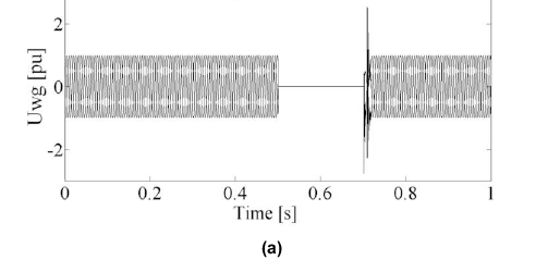
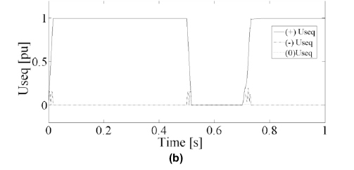
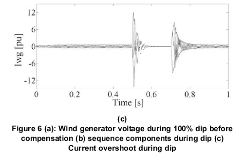
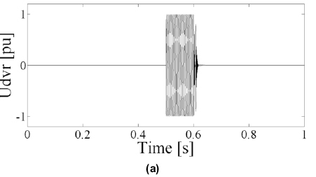
A Symmetrical Grid fault and its impact on FSIG are analysed. A voltage dip of 100%, due to a symmetrical fault, is created for 200ms as shown in Figure 6(a). The sequence components are shown in Figure. 6(b). It is found that during a symmetrical fault, only the positive sequence components are present whereas the negative sequences are found only at the beginning and the ending of dip. Figure.6(c) shows the current over shoot during voltage dip. This enormous current may damage the FSIG wind turbine and even transient failures may be encountered. Hence, usually the wind generators will be disconnected and isolated from the network for safety. But, this scenario leads to a stability problem. The sag mitigation is the only solution to avoid the aforementioned problem and to make the generator stay connected with the system. With the aid of DVR, a dip caused by fault is compensated and hence, normal operation is unaffected. Voltage sag magnitude is calculated and DVR reference voltage is generated for compensation. The DVR compensation voltage is depicted in Figure 7(a). The sag is compensated by an in-phase insertion of voltage in series with the line. Figures 7(b) and Fig. 7(c) show the compensated voltage and current at the wind generator using the vector controller.


Case II
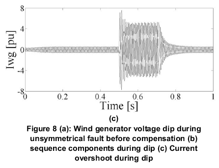
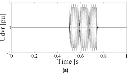
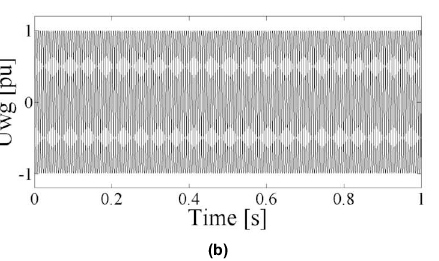
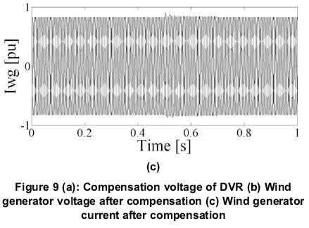
The impact of asymmetrical dip, due to phase-tophase grounded fault, is analysed in this case-II. The voltage variation at the wind generator is shown in Figure 8(a). Their sequence components are shown in Figure 8(b). The current rise due to voltage dip is shown in Figure 8(c). The impacts of unsymmetrical faults are more severe than a symmetrical fault. The negative sequence voltage and current increase the current loss and generate enormous heat, which damages the winding of the generator. The mitigation is done by generating an appropriate control signal. The reference control signal to DVR consists of two sequence parameters, one is in-phase positive sequence and the other is in phase-opposition to the negative sequence. With the combination of two sequence components, DVR inserts a voltage in series to restore the balance of the wind generator and is depicted in Figure 9(a). Hence, generator voltage and current levels are restored and are shown in Figures 9(b) and 9(c).


4.2 Stand-alone mode of operation
Case III
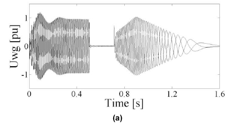
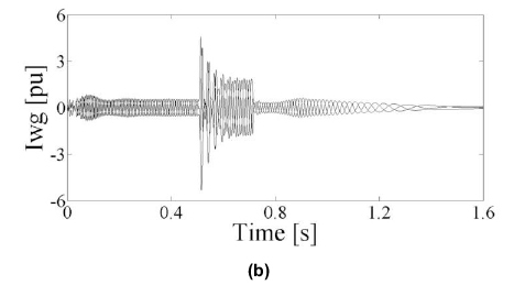
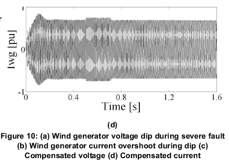
The Case III deals with impact of deep sag in a standalone wind generator. The deep voltage sag causes over current in the generator bus, which would cause severe problems. Hence, the generator is usually disconnected at such an occasion. Consequently, the reliability of the system becomes poor. The DVR provides an excellent solution for the aforementioned problems. DVR can compensate deep voltage sag, as well as reduce over current and can protect the wind generator.
A severe voltage dip, which is sustained for a period of 200ms, is created. Figures 10 (a) & (b) show the wind generator voltage and current responses for the dip. In this situation, the generator is unable to continue to operate and is unstable even when the grid voltage is re-established to the nominal value after 200ms. During starting of the wind generator, nonlinearity and oscillation are found in the wave forms. This happens due to the starting characteristics of the induction machine. The proposed DVR could compensate deep sag and recover the normal operation of wind generators. The compensated wind generator voltage and current are depicted in Figures 10 (c) & (d). The starting nonlinearity and oscillation are reduced and smooth start is accomplished using DVR.

Case IV
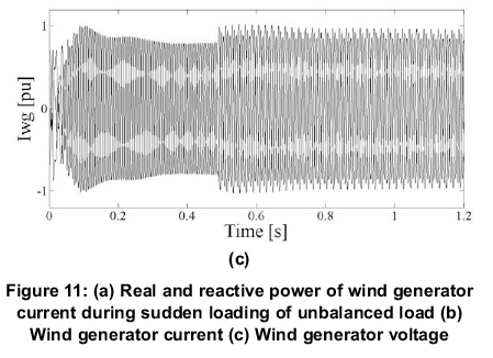
A heavy inductive load is abruptly added at 0.5s. The inclusion of load causes an increase in real and reactive power consumption as shown in Figures 11(a) & (b). It is observed that the heavy inductive load causes the power to fluctuate. As in this case, the reactive power demanded by the additional load is taken from the generator terminals. Hence, the voltage and current in the generator bus fluctuate and it is shown in Figures 11(c) & (d). The passive component employed for reactive power compensation can only support the existing load.


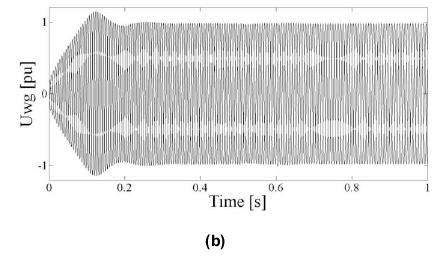
During the overload, the generator terminal voltage starts to reduce further as more reactive power is being absorbed by the generator. Being a reactive power consumer, the induction generator undergoes a reactive power dearth which leads to runaway. The DVR is a promising device which can provide an absolute solution for such problems. The proposed DVR can exchange the reactive power demand of induction generator and it also guarantees the stability of the system. The compensated real and reactive power is presented in Figures 12(a) & (b). The excess current consumption is reduced and the voltage is regained to its nominal value as shown in Figures 12(c) & (d).


5. Conclusions
The fault ride through capability of the induction generator based wind farm is improved with the aid of a DVR. The wind generator remains connected to the grid without loss of stability and guarantees the reliability of the system. The proposed DVR can mitigate voltage disturbance and provide reactive power support. It is also a suitable scheme for standalone operation. The developed models of Wind farm and DVR control strategies demonstrated the viability of the proposed scheme. The results show that the control technique is very effective and yield excellent compensation for voltage disturbance and associated problems.
References
Al-Hadidi H.K., Gole A.M., and Jacobson D.A. (2008). A novel configuration for a cascade inverter-based dynamic voltage restorer with reduced energy storage requirements," IEEE Trans. Power Del., Vol. 23, no. 2, pp. 881-888, April. 2008. [ Links ]
Awad H, Svensson J, and Bollen M.J. (2004). Mitigation of unbalanced voltage dips using static series compensator, IEEE Trans. Power Electron., Vol. 19, no. 3, pp. 837-846, May 2004. [ Links ]
Awad H, Svensson J, and Bollen M.J. (2005) Tuning software phase-locked loop for series-connected converters, IEEE Transaction on Power Delivery, Vol. 20, no. 1 pp 300-308. [ Links ]
Biricik S., Ozerdem O.C., Redif S., and Kmail M.I.O. (2013). Performance Improvement of Active Power Filter under Distorted and Unbalanced Grid Voltage Conditions, Electronics and Electrical Engineering, Vol. 19, No 1 (2013), Biricik. [ Links ]
Bollen, M.H.J. (1999). Understanding Power Quality Problems: Voltage Sags and Interruptions. New York: IEEE Press. [ Links ]
Bollen M.H.J. and Häger, M. (2005). "Impact of increasing penetration of distributed generation of the number of voltage dips experienced by end-customers," presented at the 18th Int. Conf. Electricity Distribution, Turin, Italy, June. 6-9, 2005. [ Links ]
Meyer R., De Doncker W., Li Y.W and Blaabjerg, F. (2008). Optimized control strategy for a medium-voltage DVR-theoretical investigations and experimental results, IEEE Trans. Power Electron., Vol. 23, No. 6, pp. 2746-2754, November, 2008. [ Links ]
Milanovic, J.V., Ali, H. and M. T. Aung M.T. (2207). Influence of distributed wind generation and load composition on voltage sags, Inst. Eng. Technol., Gen. Transm. Distrib, Vol. 1, No. 1, pp. 13-22, January. 2007. Mukhtiar S.M., Khadkikar V., Chandra A., and Varma R/K. (2011). Grid Interconnection of Renewable Energy Sources at the Distribution Level with Power-Quality Improvement Features, IEEE Trans.Power Syst., Vol. 26, No. 1, pp. 307-315, January, 2011. [ Links ]
Newman M.J. and Holes D.G. (2002). An integrated approach for the protection of series injection inverters", IEEE Transaction on Industrial Application; Vol. 38, No. 3, pp. 679-687, 2002. [ Links ]
Nielsen J.G, .Newman M., Nielsen H. and Blaabjerg FF (2004). Control and testing of a dynamic voltage restorer (DVR) at medium voltage level, IEEE Trans.Power Electron, Vol.19, No. 3, pp. 806-813, May 2004. [ Links ]
Ottersten R and Svensson J. (2002). Vector current controlled voltage source converter-Deadbeat control and saturation strategies, IEEE Trans.Power Electron., pp. 279-285, Mar. 2002. [ Links ]
Renders W. Ryckaert R., De Gussemé K, Stockman K., and Vandevelde L. (2008). Improving the voltage dip immunity of converter-connected distributed generation units, Elsevier Renew. Energy, Vol. 33, No. 5, pp. 1011-1018, May, 2008. [ Links ]
Siozinys V, and Baranauskas A. (2012). Smart Protection for Enhancement of Stability Conditions of Distributed Generators", Electronics and Electrical Engineering, Vol. 117, No 1 (2012), Siozinys. [ Links ]
Vaimann T., Niitsoo J., Kivipöld T., and Lehtla T. (2012), Power Quality Issues in Dispersed Generation and Smart Grids, Electronics and Electrical Engineering, Vol. 18, No 8 (2012), Vaimann. [ Links ]
Received 30 July 2013
Revised 14 October 2014

