


Services on Demand
Article
 English (pdf)
 Article in xml format
 Article references
Indicators

Related links
-
 Cited by Google
 -
 Similars in Google
Share

 Permalink
Journal of Energy in Southern Africa
On-line version ISSN 2413-3051
Print version ISSN 1021-447X
J. energy South. Afr. vol.25 n.4 Cape Town Nov. 2014
Performance analysis of a vapour compression-absorption cascaded refrigeration system with undersized evaporator and condenser
Vaibhav JainI; Gulshan SachdevaII; Surendra S KachhwahaIII
IDepartment of Mechanical and Automation Engineering, MAIT, Delhi, India
IIDepartment of Mechanical Engineering, NIT, Kurukshetra, India
IIISchool of Technology, Department of Mechanical Engineering, PDPU, Gandhinagar, India
ABSTRACT
In a present study, the performance of a vapour compression-absorption cascaded refrigeration system (CRS) under fouled conditions was analysed. The main effect of fouling is to decrease the effectiveness of the heat exchanger. Thus, the overall conductance (UA) of the heat exchanger is decreased. Hence, another interpretation of fouling is to reduce the effective size of the heat exchanger. In the present work, the percentage decrease in the overall conductance value (UA) of evaporator and condenser due to their fouling is varied from 0 to 50% and its consequences on various aspects of CRS are generated to ascertain any possible patterns. The detailed first law analysis reveals that for a clean evaporator and condenser, the electricity consumption is 67.5% less than vapour compression system (VCS) for the same cooling capacity. CRS is able to save only 61.3% of electrical energy when evaporator and condenser conductance is reduced by 50% due to fouling. Evaporator and condenser fouling decreased the COP and rational efficiency of the system by 4.7% and 10.5% respectively. It is also important to note that irreversibility in the evaporator and condenser is increased by 42.4% and 62.1% respectively, when their individual performance is degraded by 50% due to fouling.
Keywords: fouling, vapour compression, absorption, cascaded refrigeration system, first law, second law analysis
1. Introduction
Vapour compression refrigeration systems are commonly used in a variety of commercial and industrial applications due to their high cooling capacity at low temperature, but to run these systems, high grade energy is required. High grade energy or electrical energy is one of the major inputs for the economic development of any country. It is the basic need and backbone of human activities in all sectors (industry, agriculture, transportation, etc.). Therefore, for sustainable development, high grade energy should be conserved and the utilization of renewable sources should be encouraged. Electricity consumption in vapour compression refrigeration systems can be reduced by cascading it with a vapour absorption system (VAS) as they simultaneously use both the high and low grade energy for refrigeration. Further, non-conventional sources of energy such as solar and geothermal can also be used to supply low grade energy for this system.
Cimsit and Ozturk (2012) determined that 4851% less electrical energy is required in the cascaded refrigeration cycle as compared to the classical vapour compression refrigeration cycle. Wang et al. (2012) analysed the cascaded system using solar energy to supply heat in the generator and reported about 50% lower electricity consumption in the cascaded system. Fernandez-Seara et al. (2006) evaluated its adaptability in a cogeneration system and obtained a COP of 2.602 in the compression section. Seyfouri and Ameri (2012) showed that a cascaded system is more efficient and less energy consuming than a compression system to generate cooling at low temperature. Garimella et al. (2011) used a cascaded compression-absorption cycle for a naval ship application with a high temperature lift and observed 31% electrical energy reduction. Other researchers (Chinnappa et al., 1993; Kairouani and Nehdi, 2006) have also analysed the potential of CRS to reduce electrical energy consumption compared to conventional VCS.
Published literature reveals that the CRS is analysed without considering the fouling conditions (rust formation and deposition of fluid impurities on heat transfer surfaces). These surface deposits increase thermal resistance, which reduce heat transfer, may impede fluid flow, and increase pressure drop across the heat exchanger which drops the overall performance of heat exchanger equipment. Therefore, fouling in the heat exchanger will increase the energy consumption and/or decrease cooling capacity along with the system efficiency. The main effect of fouling is to decrease the effectiveness of the heat exchanger. Thus, the overall conductance (UA) of the heat exchanger is decreased. Hence, another interpretation of fouling is to reduce the effective size of the heat exchanger. Ali and Ismail (2008) experimentally investigated the performance of a room air conditioner considering the evaporator fouling. The COP of the system was reduced by 43.6% with 330 gm of fouling materials. Pak et al. (2005) conducted an experimental study to investigate the effects of air-side fouling on the performance of various condenser coils used in the air conditioning system and found that the pressure drop was increased by 22 to 37%, and heat transfer performance was decreased by 4 to 5% for the double row heat exchangers. Bultman et al. (1993) found that the COP of VCS was decreased by 7.6% when the air flow across the condenser was reduced by 40% for a constant speed fan. Bell and Groll (2011) experimentally observed 200% increment in air side pressure drop in a plate fin and micro channel coils while comparing clean and fouled conditions. Qureshi and Zubair (2011) developed a mathematical model to study the performance of a vapour compression refrigeration system under fouled conditions with alternative refrigerants.
Cascaded refrigeration systems can help to save electrical energy but relevant practical issues need to be understood (such as consequences of fouling) to ascertain these effects if such systems are to be employed in the future. Despite the importance of heat exchanger performance degradation due to fouling in a cascaded refrigeration system, a detailed analysis has not been found in the literature. Therefore, the objective of this paper is to present the effects of the consequences of condenser and evaporator outside fouling on the performance of a vapour compression-absorption cascaded refrigeration system as well as carry out an in-depth analysis of the data generated to ascertain any possible patterns. For this purpose, a property-dependent thermodynamic model that includes energy as well as exergy analysis was used. The exergy analysis is important along with the energy analysis for the process improvement of any refrigeration system (Sayyaadi and Nejatolahi, 2011). Exergy analysis accounts for the irreversibilities existing due to the finite temperature difference in the heat exchangers as well as the losses due to the non-isentropic compression and expansion in the compressors and the expansion valves, respectively.
2. Theoretical formulation of vapour compression-absorption cascaded refrigeration system
2.1 System selection
Figure 1 shows a vapour compression-absorption cascaded refrigeration system. In CRS, VCS and the single effect VAS are thermally connected in series by means of a heat exchanger called the cascade condenser. The evaporator of the compression section absorbs the refrigeration load from the water, to be cooled. The heat absorbed by the evaporator and the work input of the compressor is supplied to the evaporator of the absorption section in the cascade condenser. R22 and LiBr-Water are used as working fluid in the compression and absorption section respectively. The condenser and absorber of the proposed CRS are air cooled. The low pressure liquid refrigerant (water) of the absorption section is converted into vapour (steam) by absorbing the heat in the cascade condenser. This low pressure cold vapours i.e. steam is absorbed by the hot solution of LiBr in the absorber. The heat generated in the absorber is carried out by the circulating air.
This weak solution of LiBr, being rich in refrigerant vapour, is pumped to the generator through a heat exchanger. The pump work is negligible as compared to the compressor work of the compression section as the specific volume of the liquid is extremely small compared to that of vapour. The main energy consumption in the absorption section is only in the generator in the form of low grade energy. Water (refrigerant) gets boils in the generator due to heat transfer. Since the salt does not exert any vapour pressure, the vapour leaving the generator is a pure 'refrigerant' (water vapour). Therefore, the analyser and dephlegmator do not form a part of the system. This high pressure water vapour is condensed in an air cooled condenser. The solution returning from the generator is a strong solution of LiBr in water. The pressure of this strong solution is reduced to absorber pressure through a pressure reducing valve.
2.2 Thermodynamic modelling of the vapour compression-absorption cascaded refrigeration system
The following assumptions are made in modelling the CRS (Cimsit and Ozturk, 2012):
1. The system is in a steady state.
2. All the pressure losses in different components of the system are neglected.
3. Heat loss in the suction and liquid lines are neglected in this work.Table 1
4. Refrigerant at the exit of the evaporator, cascade condenser and condenser is saturated vapour.
5. Isentropic efficiency of compressor is assumed as constant.
6. The processes occurring in the expansion valves are isenthalpic.
Thermodynamic modelling includes the following set of governing equations for a particular system component:
(i) Mass balance, 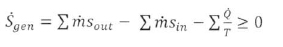
(ii) Energy balance, 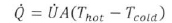
(iii) Entropy generation rate. 
Applying these three fundamental equations to all the components of a CRS, the governing equations in the modelling of individual components are given in . The irreversible loss due to entropy generation is determined by means of the Gouy-Stodola law:
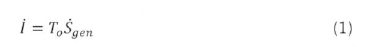
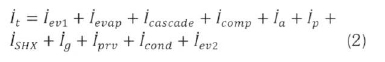
The total irreversibility of the system is given by:

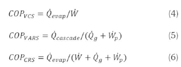
The COP of various systems is given by:
Efficiency defect is defined as the ratio between the exergy flow destroyed in each component and the exergy flow required to sustain the process. Efficiency defect (δk) of kth component of the system is expressed as (Gomri and Hakmi, 2008):
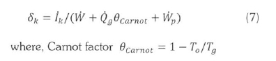
where. Carnot factor θCarnot= 1 - T0/Tg
The thermodynamic perfection of the process is measured by rational efficiency which can be defined as (Nikolaidis and Probert, 1998):

In the present paper, the effect of the evaporator's and condenser's outside fouling is taken into account. The effect of fouling is to reduce the heat transferred by the heat exchangers. As one of the fluids is undergoing a phase change, the following equation (from heat exchanger theory) is applied (Qureshi and Zubair, 2011):
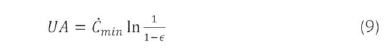
The term UA in the heat transfer rate equation, is caIled the overall conductance. In Eq. (9), Ċminis the thermal capacitance rate is the fluid which is not undergoing a phase change. The value of UA will decrease due to fouling and can be presented as a percentage UA,,,., by the following equation:

In the present work, the percentage decrease in the UA value due to fouling was varied from 0 to 50% for evaporator and condenser, where zero value refers to clean conditions.
2.3 Model validation
The thermodynamic model equations given in Table 1 are highly nonlinear in nature and have been solved numerically in Engineering Equation Solver (EES). The thermophysical properties of refrigerants are taken from built-in functions. In CRS, VCS and VAS are connected in series where condenser of the compression section rejects heat to the evaporator of the absorption section. Models of VCS, VAS and CRS are individually validated.
Qureshi and Zubair (2011) have studied the effect of fouling on VCS using R134a as refrigerant. Table 2 shows the comparison of the current model results with Qureshi and Zubair (2011) for same input conditions. The percentage error in the results is within 0.03%.
The results of the thermodynamic model of VAS are compared with those by Kaynakli and Kilic (2007). The following set of data is used to generate the results for comparison purposes: Tcond= 35°C, Ta= 40°C, Tg= 90°C, Tevap= 5°C,  = 10 kW, ηp= 0.95 and ε = 0.7. Water-LiBr is considered as the working pair. The percentage error found in the prediction of COP is 2.60%. The large error in prediction of COP is due to usage of different correlations to determine the thermophysical properties of Water-LiBr. In this paper, the thermo-physical properties of Water-LiBr are taken from built-in functions of EES.
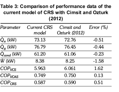
Data from the work of Cimsit and Ozturk (2012) related to CRS was also used for the verification of the current CRS model. The following set of data was used to generate the results for comparison purposes: Tcond= 40°C, Ta= 40°C, Tg= 90°C, Tevap= 10°C, = 50 kW, ηp= 0.90, ηisen= 0.80 and ε = 0.6. Water-LiBr is assumed as the working fluid in the absorption section and R134a is considered in the compression section. The maximum error in the prediction of calculated parameters is found to be 1.6% (Table 3).
3. Results and discussion
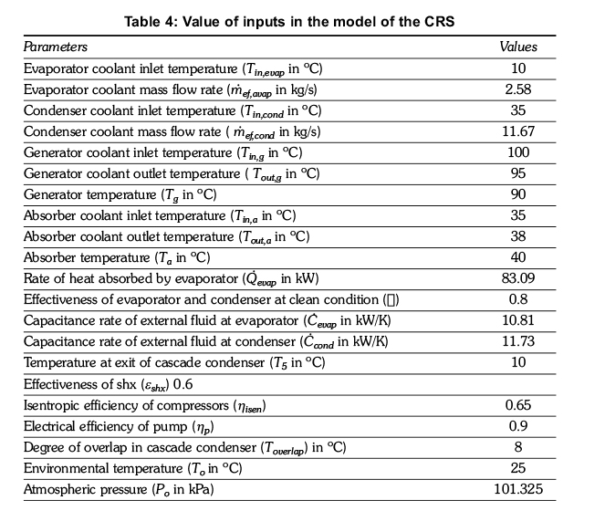
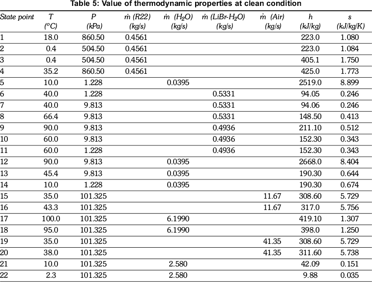
The thermodynamic model has been applied to evaluate the performance of a typical CRS as shown in Figure 1. The values of inputs as obtained by the literature survey are given in Table 4. Thermodynamic properties at inlet and outlet of each component of the CRS are presented in Table 5 for clean conditions. The main purpose of a CRS is to reduce the consumption of electricity in the compressor of the vapour compression section. This is done by lowering the temperature of the condenser of VCS. The following values can be predicted for VCS operating under the same conditions as mentioned in Table 4: Tevap= 0.4°C, Tcond= 46.8°C, = 0.5687 kg/s, ηv= 95.33%,= 27.94 kW, = 111.03 kW and COP = 2.972.
When we compare the performance of a CRS with a VCS operating under the same conditions (Table 4), it can be shown that refrigerant (R22) mass flow rate in CRS is reduced by 19.81%. The present thermodynamic model predicts the condenser and evaporator temperatures for both the VCS and the CRS. Based on the cooling capacity and the effectiveness of the evaporator, the evaporator temperature for the systems is 0.4°C. The predicted condenser temperatures are 46.8°C and 45.4°C for VCS and CRS respectively. The reduction in the condenser temperature also gives a lower temperature of air at the condenser exit after cooling. Table 6 represents the values of performance parameters for the CRS.
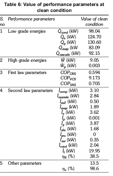
The generator heat transfer rate is 130.60 kW which is highest. The heat transfer rates in the condenser and absorber are 98.04 kW and 124.70 kW respectively. The effect of the pump on the total energy inputs is found to be negligible. The prescribed temperature (T5) for refrigerant (water vapour) and degree of overlap are 10°C and 8°C respectively in the cascade condenser. Thus, the refrigerant (R22) reached a temperature of 18°C at the exit of the cascade condenser. The power consumption is reduced by 67.5% in the compressor of CRS as compared to equivalent VCS. The volumetric efficiency of compressor is also increased by 3.4%. As subsystems of CRS, COP of vapour compression and vapour absorption subsystems are 9.173 and 0.705 respectively. Higher value of COP for the vapour compression refrigeration subsystem is due to low refrigerant temperature at the compressor exit which leads to reduction in electricity requirement of the compressor. The heat rejection in the condenser of CRS is reduced by 11.6% as compared to VCS.
Table 6 also shows the irreversibility rate of the system components. From an irreversibility rate point of view, the most sensitive component in compression and absorption sections of a CRS are compressor and generator. Their irreversibility contributes 15.5% and 19.4% respectively in total irreversibility of system (at clean condition). It is also apparent that the most efficient components of a CRS are pump and pressure reducing valve in which approximate zero entropy generation is observed. In the decreasing order of irreversible loss, these components can be arranged in the sequence as generator, absorber, compressor, cascade condenser, condenser, evaporator, solution heat exchanger, expansion valves, pump and pressure reducing valve. The total irreversibility rate for the entire CRS and rational efficiency are 19.95 kW and 38.5% respectively.
The total fixed cost of the CRS increases due to addition of VAS components, but the running cost will decrease due to small electricity consumption in compressor and utilization of low grade energy in the generator. The hot water obtained from the solar energy is assumed to be the source of heat for the generator of VAS in the present analysis.
3.1 Effect of evaporator fouling
The effects of evaporator fouling on the performance characteristics of CRS are shown in Figures 2 to 4. Evaporator conductance is varied from 0 to 50%, where 0 refers to clean condition. The main effect of fouling is to decrease the value of UA, which in turn, decreases the effectiveness of the heat exchanger. The effectiveness of the evaporator in a clean condition is assumed to be 0.8 and it is decreased up to 0.55, when evaporator conductance is reduced by 50%. It is observed from Figure 2 that there is 31% reduction in its effectiveness which directly lowers the cooling capacity of the system. The reduction in evaporator effectiveness caused the evaporator temperature to decrease from 0.4°C to -2.5°C, while keeping the inlet temperature of external fluid to be cooled as constant. Further, it also decreased the temperature of cas- cade condenser (T1) and condenser temperature (T13) from 18°C to 17.3°C and 45.4°C to 44.5°C respectively. Moreover, as the evaporator temperature is decreased, the specific volume of the refrigerant at the compressor inlet is increased. Therefore, volumetric efficiency of the compressor is decreased by 0.27% with 50% reduction in evaporator conductance, as depicted in Figure 2.
Figure 3 shows the effect of evaporator fouling on low grade and high grade energies. Cooling capacity of the system is decreased from 83.09 kW to 74.93 kW and the outlet temperature of external fluid i.e. water to be cooled is increased from 2.3°C to 3.0°C with 50% reduction in evaporator conductance. Reduction in the cooling capacity of the system due to fouling also lowers the thermal load in the absorption section of the cascaded system. Figure 3 shows that the thermal load is decreased by 8.5% with the 50% reduction in evaporator conductance. Therefore, the heat load in the generator, absorber and condenser of the absorption section is also decreased. The % variation in the reduction of heat load at absorber, condenser and generator is the same as that of the cascade condenser because their variation ultimately depends on the variation in heat load a thet cascade condenser. Moreover, the mass flow rate of external fluids flowing in the absorber and generator is also decreased due to lower heat load. Lower heat load in the condenser also caused a substantial drop of air temperature at condenser exit. Increase in specific volume of refrigerant at the compressor inlet due to evaporator fouling increased the electric power consumption (compressor work) in compressor by 3.6%. The present cascaded system saves 67.5% of compressor work in VCS at clean condition. But due to fouling, it would now be able to save 66.4% of compressor work.
Figure 4 depicts the variation of COP of system with evaporator conductance. As discussed for Figure 3, evaporator fouling decreased the cooling capacity and increased the electric power consumption in compressor; it is obvious to see that COP of the compression section is decreased due to evaporator fouling. COP of the compression section is reduced by 12.9% with 50% reduction in evaporator conductance. COP of the absorption section strongly depends on thermal load at cascade condenser and heat required in the generator. Figure 3 shows variation in the heat load of the generator and is almost the same as that in the cascade condenser. Hence, COP of the absorption section remained constant with evaporator fouling. COP of the cascaded system depends on its cooling capacity, electric power consumption in compressor of compression section and heat load on generator. The overall effect of all these parameters is to decrease the COP of cascaded system. There is a 2.3% fall in overall COP of CRS with 50% reduction in evaporator conductance.
The irreversibility in the evaporator is increased by 42.4% due to 50% reduction in evaporator conductance. Rational efficiency denotes the degree of thermodynamic perfection of the process. As shown in Figure 4, rational efficiency for CRS is decreased from 38.5% to 36.2% for 50% reduction of evaporator conductance.
3.2 Effect of condenser fouling
The effect of only condenser conductance on the performance parameters of CRS are shown in Figures 5 to 7. The evaporator is assumed to be clean in this section. The effectiveness of the condenser at a clean condition is 0.8 and it is decreased by 30.9% with 50% reduction in condenser conductance. Figure 5 shows the variation of effectiveness of condenser and volumetric efficiency of compressor with condenser conductance. The effectiveness of the condenser is decreased which increased the temperature of the condenser from 45.4°C to 50.0°C. It further caused the temperature of the cascade condenser and evaporator to increase by 19.6% and 48.8%. The pressure ratio across the compressor in clean condition is 1.70 and it increased to 1.86 with 50% reduction in condenser conductance. This 9.4% increase in the pressure ratio lowered the volumetric efficiency of compressor by 0.3%.
Increase in pressure ratio across the compressor increased the compressor work by 17.5% as shown in Figure 6, which decreased the saving in electricity consumption by 8.7% as compared to clean conditions. Moreover, the cooling capacity of the system is decreased by 2% as shown in Figure 6 and it further increased the temperature of the chilled water at the evaporator exit by 6.5%. However, reduction in the condenser conductance decreased the other low grade energies. The percentage change in the variation of generator, absorber and cascade condenser depends on % variation in the condenser heat load. Hence, their variation is almost the same.
Figure 7 presents the variation of COP of the system with decrease in condenser conductance. Condenser fouling causes the cooling capacity of evaporator to decrease and compressor work to increase. Hence, COP of the compression section decreases with condenser fouling. There is 16.6% reduction in COP of the compression section with 50% reduction in condenser conductance. COP of the vapour absorption section slightly increases with condenser fouling. COP of absorption section mainly depends on thermal load at cascade condenser and generator. Thermal load in generator and cascade condenser is decreased by 0.8% and 0.5% respectively. Hence, their overall effect is to increase the COP of absorption section. The COP of CRS is decreased by 2.6% with 50% reduction in condenser conductance. Hence, condenser fouling is more severe as compare to evaporator fouling.
The high temperature gradient inside the condenser due to its fouling caused its irreversibility to increase by 62.1%. The overall irreversibility of system is increased by 8.2% and the rational efficiency of system is decreased by 5.5%, with 50% reduction in condenser conductance.
3.3 Combined effect of evaporator and condenser fouling
The effect of both evaporator and condenser fouling are considered in this section. Figure 8 to 10 shows the variation of performance parameters of the system with equal degradation in the evaporator and condenser. The effectiveness of both the components is decreased by 30.9% with 50% reduction in their conductance. It caused the temperature of the evaporator to decrease from 0.4°C to -2.3°C, whereas the condenser temperature is increased from 45.4°C to 48.8°C. It also increased the temperature of the cascade condenser from 18°C to 20.6°C.
Figure 8 shows that the volumetric efficiency of the compressor is decreased by 0.6% with 50% reduction in evaporator and condenser conductance. Reduction in the evaporator temperature further caused the specific volume of refrigerant to increase by 9.9%. The pressure ratio across the compressor reached to 2.10 at this point. Hence, compressor work is increased from 9.06 kW to 10.80 kW. Thus, CRS is able to save only 61.3% of electric power as compared to 67.5% in clean condition.
Figure 9 depicts that the variation in the thermal loads at the condenser, absorber, generator and cascade condenser and are almost the same. The cooling capacity of the evaporator is decreased by 10.9% and the heat rejected in the condenser is 90.03 kW under this situation whereas this magnitude was 97.32 kW under the case of condenser fouling only.
Figure 10 presents the variation of COP of the system with decrease in evaporator and condenser conductance. COP of the compression section is decreased with reduction in evaporator and condenser conductance. The trend is obvious due to reduction in cooling capacity and increment in compressor work with evaporator and condenser fouling. The COP of compression section is reduced by 25.3% with 50% reduction in evaporator and condenser conductance. COP of the absorption section is slightly increased with evaporator and condenser fouling. COP of the absorption section mainly depends on thermal loads at cascade condenser and generator. Thermal load at the generator is decreased by 8.26% whereas it is decreased by 8.1% at cascade condenser. Hence, their overall effect is to slightly increase the COP of the absorption section. The total COP of CRS is decreased by 4.7% with degradation in evaporator and condenser performance of 50% reduction in evaporator and condenser conductance.
The irreversible loss in the evaporator and condenser is increased by 38.4% and 39.1% respectively. Hence, the condenser is more sensitive as compared to the evaporator. The total irreversibility of CRS is increased by 5.9% with evaporator and condenser fouling. The rational efficiency of the system is decreased by 10.5% with 50% reduction in evaporator and condenser conductance as depicted by Figure 10.
4. Conclusions
In this paper, an extensive thermodynamic study of a vapour compression-absorption cascaded refrigeration system under fouled conditions has been presented and it is concluded that:
1. Electric power requirement in VCS is reduced by 67.5%, when it is cascaded with an absorption system in clean condition.
2. Electric power saving by CRS is decreased, when the evaporator and/or condenser foul. Degradation in their performance also decreased the cooling capacity of the system. When both the components foul, the saving in electricity consumption is reduced by 9.22%.
3. The heat load at generator, absorber, and condenser is decreased, when the evaporator and/or condenser foul.
4. COP of the compression section and total COP of CRS are decreased with degradation in the performance of evaporator and/or condenser whereas COP of the absorption section is decreased only in case of evaporator fouling. The total COP of the system decreased by 4.7%, when both these components foul.
5. Irreversibility which can be viewed as the wasted work potential is increased drastically in the evaporator and condenser when their individual fouling is taken into consideration. The irreversibility in the evaporator is increased by 42.4% due to its fouling whereas the high temperature gradient inside the condenser due to its fouling caused its irreversibility to increase by 62.1%. Further, the rational efficiency of the system is decreased by 10.5% when both the components foul.
Nomenclature
C Heat capacitance rate of external fluid (kW/K)
c Concentration of LiBr solution (kg LiBr/ kg water)
cpSpecific heat at constant pressure (kJ/kg K)
COP Coefficient of performance
f Circulation ratio
h Specific enthalpy (kJ/kg)
I Irreversibility rate (kW)
m Mass flow rate (kg/s)
P Pressure (kPa)
Q Heat transfer rate (kW)
τ Ratio of clearance volume to the displacement volume
s Specific entropy (kJ/kg K)
SgenEntropy generation rate (kW/K)
T Temperature (°K)
UA Overall conductance (kW/K)
UAperPercentage overall conductance (%)
v Specific volume (kg/m3)
VoVolumetric flow rate (m3/s)
W Power input (kW)
Greek symbols
ε Effectiveness of heat exchanger
η Efficiency
δ Efficiency defect
θcarnotCarnot factor
ρ Density of LiBr solution (kg/m3)
Subscripts
a absorber cascadecascade
cl clean condition
comp compressor
cond condenser
ef external fluid
ev expansion valve
evap evaporator
g generator
in inlet condition
isen isentropic
m results of current model
o environmental condition
out outlet condition
p pump
prv pressure reducing valve
R rational
ref refrigerant
shx solution heat exchanger
t total
v volumetric
1,2,3....state points
References
Ali, A.H.H. and Ismail, I.M. (2008). Evaporator air side fouling effect on performance of room air conditioners and impact on indoor air quality. HVAC and R Research, 14(2): 209-219. [ Links ]
Bell, I.H. and Groll, E.A. (2011). Air side particulate fouling of micro-channel heat exchangers: experimental comparison of air side pressure drop and heat transfer with plate fin heat exchanger. Applied Thermal Engineering, 31: 742-749. [ Links ]
Bultman, D.H., Burmeister, L.C., Bortane, V and Tenpas, P.W. (1993). Vapour-compression refrigerator performance degradation due to condenser air flow blockage. ASME 93-HT-34: 1-13. [ Links ]
Chinnappa, J.C.V, Crees, M.R. and Murthy, S.S. (1993). Solar-assisted vapour compression/absorption hybrid air-conditioning systems. Solar Energy, 50(5): 453-458. [ Links ]
Cimsit, C. and Ozturk, I.T. (2012). Analysis of compression-absorption hybrid refrigeration cycles. Applied Thermal Energy, 40: 311-317. [ Links ]
Fernandez-Seara, J., Sieres, J. and Vazquez, M. (2006). Compression-absorption hybrid refrigeration system. Applied Thermal Energy, 26: 502-512. [ Links ]
Garimella, S., Brown, A.M. and Nagavarapu, A.K. (2011). Waste heat driven absorption/vapour-compression hybrid refrigeration system for megawatt scale, high-flux, low-temperature cooling. International Journal of Refrigeration, 34: 1776-1785. [ Links ]
Gomri, R. and Hakmi, R. (2008). Second law analysis of double effect vapour absorption cooler system. Energy Conversion and Management, 49: 3343-3348. [ Links ]
Kairouani, L. and Nehdi, E. (2006). Cooling performance and energy saving of a compression-absorption refrigeration system assisted by geothermal energy. Applied Thermal Engineering, 26: 288-294. [ Links ]
Kaynakli, O. and Kilic, M. (2007). Second law based thermodynamic analysis of water lithium bromide absorption refrigeration system. Energy, 32: 1505-1512. [ Links ]
Nikolaidis, C. and Probert, D. (1998). Exergy-method analysis of two-stage vapour compression refrigeration-plants performance. Applied Energy, 60: 241-256. [ Links ]
Pak, B.C., Groll, E.A. and Barun, J.E. (2005). Impact of fouling and cleaning on plate fin and spine fin heat exchanger performance. ASHRAE Transactions, 111(1): 496-504. [ Links ]
Qureshi, B.A. and Zuber, S.M. (2011). Performance degradation of a vapour compression refrigeration system under fouled conditions. International Journal of Refrigeration, 34: 1016-1027. [ Links ]
Sayyaadi, H. and Nejatolahi, M. (2011). Multi objective optimization of a cooling tower assisted vapour compression refrigeration system. International Journal of Refrigeration, 34: 243-256. [ Links ]
Seyfouri, Z. and Ameri, M. (2012). Analysis of integrated compression-absorption refrigeration systems powered by a microturbine. International Journal of Refrigeration, 35: 1639-1646. [ Links ]
Wang, L., Ma, A. and Tan, Y (2012). Study on solar assisted hybrid refrigeration system. Energy Procedia, 16: 1503-1509. [ Links ]
Revised 17 May 2013
19 September 2014

