


Servicios Personalizados
Articulo
 Inglés (pdf)
 Articulo en XML
 Referencias del artículo
Indicadores

Links relacionados
-
 Citado por Google
 -
 Similares en Google
Compartir

 Permalink
Journal of Energy in Southern Africa
versión On-line ISSN 2413-3051
versión impresa ISSN 1021-447X
J. energy South. Afr. vol.25 no.2 Cape Town may. 2014
Use of hybrid solar-wind energy generation for remote area electrification in south-eastern Nigeria
Damian B N NnadiI; Charles I OdehI; Crescent OmejeII
IDepartment of Electrical Engineering, University of Nigeria, Nsukka, Nigeria
IIDepartment of Electrical Engineering, University of Port Harcourt, River State, Nigeria
ABSTRACT
This paper presents simulated hybridized solar-wind generation as an alternative for rural dwellers that do not have access to a conventional grid connection. Solar and wind were used as the main sources of energy with battery storage. Each power source has a DC-DC converter to control the power flow. An axial flux permanent magnet generator, which is suitable for a location with a low wind speed, was driven by the wind turbine. By using this generator, the efficiency of the system increased since certain losses were removed. The perturbation and observation method of MPPT is used to achieve maximum power extraction from the solar panel. The hybrid system was modelled in Matlab/Simulink software. A squirrel cage induction motor was used as the electrical load to the system load. The results obtained for the proposed hybrid system indicates that it can be used as an isolated power supply. By doing so, it improves the standard of living and hence, increasing total number of citizens using energy in the country.
Keywords: hybrid solar-wind, converter, solar maximum power point tracker, induction motor, permanent magnet synchronous generator
1. Introduction
Energy is the bedrock of any nation's economic development. To meet the electrical needs, various options have been proposed. Renewable energy technology is now considered as a viable alternative to the traditionally used fossil fuel plants. The reasons being that fossil fuel is depleting and, at the same time, has negative effects globally. Such effects include air pollution, greenhouse effect, depletion of the ozone layer etc. In Nigeria today, at the rural level, where about 70% of the population lives, the percentage access to grid electricity is slightly above 18% (Sambo, 2006). This necessitates this research.
This paper presents a design simulation of a stand-alone hybrid solar-wind energy generation system for remote areas of Nsukka in south-eastern part of Nigeria located Lat. 6° 51/ N and Long. 7° 35/ E. Solar resources for the design of the system were obtained from the National Aeronautics and Space Administration (NASA) Surface Meteorology and solar energy website at a location of 6° 51' N latitude and 7° 35' E longitude, with annual average solar radiation of 4.92kWh/m2/d (NASA, 2013). Wind-solar hybrid system consists of an emulated wind turbine generator, solar PV unit and battery storage; since is anticipated that at one time or another, there may be little or absence of both wind and solar power. During these times, the battery unit should be capable of supplying 100% of the plant's required energy. However, this will depend on the state of charge (SOC) of the battery.
In remote locations, stand-alone systems can be more cost-effective than extending a power line from the national grid (the cost of which can range from two to three million naira depending on the distance of the location from the grid lines). However, these systems are also used by people who live near the grid and wish to obtain independence from the power provider or demonstrate a commitment to non-polluting energy sources. The choice of this hybrid system stems from the fact that these two sources are complementary since sunny days are usually calm and strong winds are often accompanied by cloud and may occur at night. A combined plant, therefore, has higher availability than either individual source and so needs less storage capacity. This concept may provide power supply to the end user; which may either be any of the following: remote/rural village electrification, ideal for cell phone recipient (base) stations, residential colonies and apartments for general lighting/water pumping and street lighting (Parita et al., 2012), banking sectors, hotels and business areas.
A study on the wind energy potentials for a number of Nigerian cities shows that the annual wind speed ranges from 2.32 m/s for Port Harcourt (south-south of Nigeria) to 3.89 m/s for Sokoto (north-north part of Nigeria) (Ajao et al., 2011). From the research work of Ojosu and Salawu, (Adramola and Oyewola, 2011), the annual average wind speed for Enugu state in which Nsukka is part of is 2.1 - 3.0m/s (isovents at 10 m height). Similarly, solar energy (irradiance) availability in Nigeria through the same span - that is, from southern to northern part of Nigeria, throughout the year with reserve estimate is 3.5 - 7.0 kW/m2/day (Sambo, 2009).
Nigeria receives 5.08 x 10¹² kWh of energy per day from the sun and if solar energy appliances with just 5% efficiency are used to cover only 1% of the country's surface area, then 2.54 x 10⁶ MWh of electrical energy can be obtained from solar energy (Chiemeka and Chineke, 2009). With this information, hybrid solar-wind generation should work out very well in the south-eastern part of Nigeria.
2. System components
2.1 Photovoltaic systems
A photovoltaic system is commonly modelled using the Shockley diode principles, which can be found in the literature. The model of the solar cell can be realized by an equivalent circuit that consists of a From Figure 1, the P-N junction has a certain depletion layer capacitance, which is typically neglected for modelling solar cells, therefore Ic is zero. Hence, these equations:


where I : Solar cell current (A); Ipv :Light generated current (A) ; I0 :Diode saturation current (A); q : Electron charge (1.6x10⁻¹⁹ C); K : Boltzman constant (1.38x10⁻²³ J/K); T : Cell temperature in Kelvin(K); V : Solar cell output voltage (V); Rs : Solar cell series resistance (H); Rsh: Solar cell shunt resistance (H), ID: diode current(A) and Ish: short circuit current.
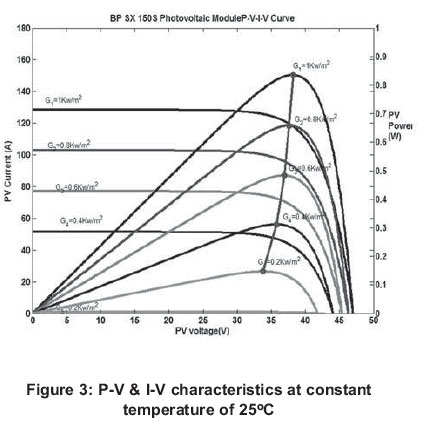
Equations (1) to (5) were modelled in MATLAB-SIMULINK software. The hybrid Polycrystalline PV panel with these ratings were used. Maximum power Pmax= 150W, Maximum current Imax = 4.5A, short-circuit current Isc = 4.75A and open-circuit voltage Voc = 43.5V. Four of such panels were connected in series. The choice for this PV panel is due to its high efficiency while compared with mono-crystalline or Polycrystalline alone
Figures 2 (a & b) denote the P-V and I-V characteristics of a photovoltaic system at different temperatures of 25oC and 50oC at varying solar irradiance respectively. At 50oC, there was decrease in power output due to the voltage decrease at that temperature. Similarly, current change was small whereas, the powers as well as the current increases with increase in solar irradiance.
Figure 3 shows P-V and I-V characteristics at constant temperature of 25oC with varying solar irradiance.
2.2 Wind turbine unit
This unit consists of a wind turbine model from a power system sub-library, 5kW permanent magnet sychronous generator, wind turbine driven control (which controls the generator speed via the mechanical torque of the generator), and pitch-angle controller (the pitch angle controller is active only in high wind speeds). In such circumstances, the rotor speed can no longer be controlled by increasing the generated power, as this would lead to overloading the generator and also the over speed of the turbine. Therefore, the blade pitch angle is changed in order to limit the aerodynamic efficiency of the rotor. This prevents the rotor speed from becoming too high, which would result in mechanical damage. The optimal pitch angle is approximately zero below the nominal wind speed. A variable-speed pitch-regulated wind turbine is considered in this paper, where the pitch angle controller plays an important role.
Figure 4 shows the groups of Cp- curves of the wind turbine used in this study at different pitch angles (Chinchilla et al., 2006). It is observed that from Figure 4 the value of Cp can be changed by changing the pitch angle (0). In other words, the output power of the wind turbine can be regulated by pitch angle control.
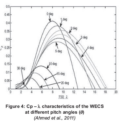
In analysing the wind power Pwind (in watts) extracted from wind, the following equations were obtained:

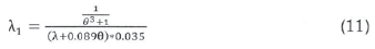
where p is the air density (1.22kg/m3), A is the area swept by the rotor blades in m2, and V is the wind velocity in m/s. Cp is called the power coefficient or the rotor efficiency; where the theoretical maximum value is 0.593 (Anandavel et al, 2005) and is a function of tip speed ratio (TSR or λ) and pitch angle (θ).
Cp is represented as a function of the tip speed ratio À given by Monica et at. (2006) as:
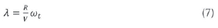
where ωt is the turbine speed.
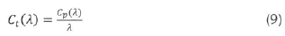
It is important to note that the aerodynamic efficiency is maximized at the optimum tip speed ratio. The torque value obtained by dividing the depends on the value chosen for the constant Kp. turbine power by turbine speed is obtained as follows:
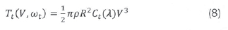
Where C, (λ) is the torque co-efficient of the turbine given by (9) and area swept by the blades is given by this; A = πR2
The power co-efficient Cp is given by Anandavel et ai. (2005) as shown in equation (10):
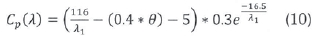
Where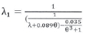
The turbine is connected to the rotor of the generator via a shaft. The turbine, shaft and generator are modelled as a single rotating mass:
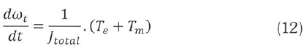
Te is the electromechanical torque developed by the electrical machine in N.m (when the electrical machine is operated as a generator Te will be negative), Tm is the mechanical torque delivered by the wind turbine in N.m and Jtotal is the moment of inertia of the entire mechanical system in kg-mz.
In per unît (p.u.) values equation (12) becomes:
Where rm is the time constant in sec.
Figure 5 is a pitch angle controller, which is a proportional (P) controller. Using this controller type implies that the rotor speed is allowed to exceed its nominal value by an amount that depends on the value chosen for the constant Kp.
The choice of direct driven PMSG is due to the fact that it has no gearbox which produces losses due to friction; and hence, the frictional torque in a gearbox which leads to starting problems of such generator is avoided. Similarly, the gearbox needs oil and regular maintenance results to reduced overall system reliability. Hence, due to the higher efficiency of PMSG and the wide range of speed control in the PMSG, it stands the best option for this research work.
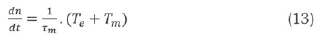
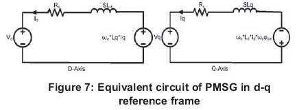
Almost all drive systems use the dynamic dqo (direct-quadrature-zero axis) model of a machine. This converts the 3 phase alternating current quantities to direct current quantities, which can be easily controlled by a simple proportional integral (PI) controller. The transformation from 3 phase variables with time varying (abc) frame to stationary dqo-frame is as defined in Figure 6 (Heier, 1998).
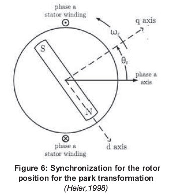
Machine equations based on the rotor reference position are described in Equations (14) and (15) and they are marked with the subscript 'r'.
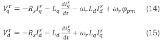
The variables Rj, Lj and are the stator resistance, direct and quadrature inductance respectively of a permanent magnet synchronous generator, where = Lq = Ls.
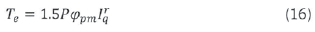
Figure 7 shows the equivalent circuit of the PMSG in d-q axis. The electrical torque is shown in equation (16). It should be noted that to control the electrical torque, the q-axis current can be controlled, hence the essence of (16).
The back emf (Epm) produced by the magnets depends on the mechanical rotational speed ωm (rad/sec). Therefore,

Where ωe is the electrical rotational speed (rad/sec) and φpm is the flux linkage established by the magnets in weber. Hence,

Where P is the number of pole pairs of the generator.
The prime mover for PMSG is a wind turbine with optimum power control and pitch angle control. The external inputs to the turbine are wind speed and rotor speed. Optimum power is obtained from the Power-Speed characteristics, which depend upon the speed of the turbine. A rotor side converter is controlled by vector control. The main objectives are for active and reactive power flow control and maximum power point tracking. The grid side converter's main objective is to regulate the DC link capacitor voltage and this converter controls the power flow between the DC bus and the AC side.
2.3 Energy storage device model
The energy storage devices are used for three purposes: energy stabilization, ride through capability and dispatchability. The energy stabilization permits the hybrid system to run at a constant stable output level with the help of the energy storage devices, even if the load fluctuates rapidly. The ride through capability is the capability of the energy storage device that provides the proper amounts of energy to the loads, when the hybrid system generation units are unavailable be it in the night or in a period of faults. There is a controller that charges or discharges the battery to fix DC link voltage.
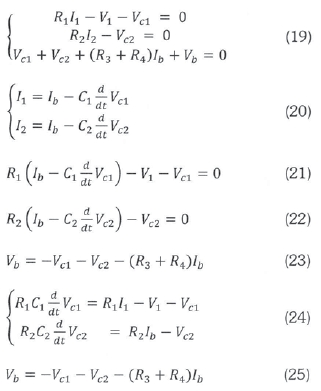
In the analysis, the structure of the battery consists of a constant dc source, and internal capacitances and resistances shown in Figure 8.
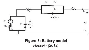
Considering Figure 8, from analysis one was able to get the following formulae
The model of the battery suitable for this project is as shown and the battery should be a deep cycle battery. This type of battery can withstand fluctuations as well as discharge slowly.
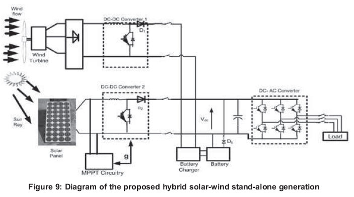
3. Proposed hybrid energy system
Wind and solar energy are converted into electricity and then sent to loads or stored in a battery bank. The topology of the hybrid energy system consists of a PV array and variable speed wind turbine, coupled to a permanent magnet synchronous generator (PMSG) with a deep cycle battery as a back-up. The two energy sources are connected in parallel to a common dc bus line through their individual DC-DC converters. The load may be dc connected to the dc bus line or may include a PWM voltage source inverter to convert the dc power into 50Hz AC supply.
The two generating sources were controlled individually, of which their output goes to the dc bus line to feed the isolating dc load or to the inverter section of the system for ac load. The use of a battery charger and its accessories were to keep the battery fully charged at a constant dc bus line voltage and also for monitoring/protection of the battery in case of over charge or over discharge. The voltage from both the wind turbine and solar panel were connected to the battery via a battery charger. This device has a regulator that allows only the required voltage that will charge the battery in to the charger. When the output of the system is not available, the battery powers the dc load or discharges to the inverter to power ac loads, through a discharge diode Db. A battery discharge diode Db is to prevent the battery from being charged when the charger is opened after a full charge. As depicted in the system configuration represented in Figure. 8, the Vdc is set to a fixed dc bus line voltage and the output dc voltage from each source is controlled independently for both generation systems (Yerra et al., 2012).
3.1 Maximum power point tracker for the PV systems
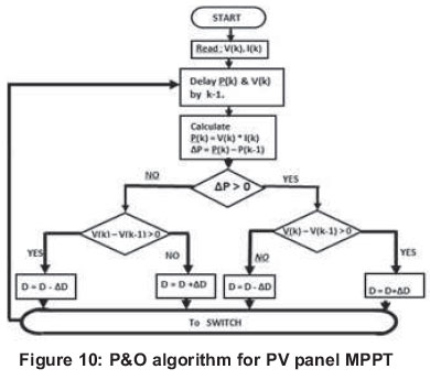
The output of the PV was fed in to a boost converter before connecting it in to DC link. The essence of this is to boost PV output. The MOSFET switch of the boost converter for the PV system will be triggered by the P&O algorithm of the MPPT of the PV panel, which will be modulated by a triangular wave to get a pulse width modulated signal. This is to ensure that the maximum power of the PV system will be transferred to the load via an inverter. The P&O method of MPPT measurement senses both the voltage and current inputs from the PV panels arbitrarily, and computes the power and then increments or decrements the voltage and power. The new data is compared to the previous readings. If the power increases, the voltage is moved in the same direction as the last adjustment. This continues until the new value shows less power than the previous one. The direction is then changed to try and reach the peak power output. The algorithm is shown in Figure 10.
Similarly, the output of the PMSG was also fed into a three phase rectifier through a buck converter in that the voltage input- output ratio is controlled by a PWM to get a dc signal, which was linked up with the dc link.
However, the controller in the charger switches the battery on and off if neither the PV nor the wind turbine produces enough voltage and if both produce voltage respectively. The voltages from both sources were connected to the dc link form which it was connected through a three phase inverter.
4. Results of the simulations
The results of the simulations were presented asshown in Figures 11-16.
4.1 Evaluation of the results
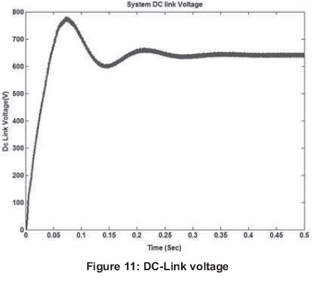
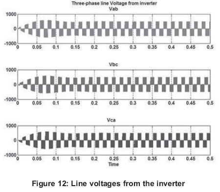
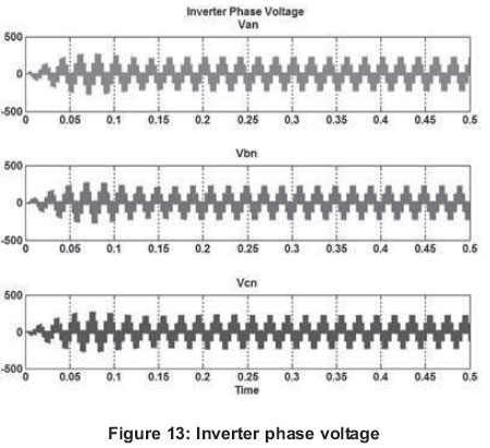
When the wind turbine output, which is three-phase is connected via a three-phase rectifier, the output of the rectifier is connected to a dc-link together with the PV system output, the result is shown in Figure 11 and this dc-link capacitor voltage is 0.64kV. However, these dc-link capacitor voltages of the hybrid source were connected through a three-phase PWM inverter. Figure 12 shows the two-level pulse width modulated (PWM) line voltages which were used to operate a 4kW squirrel caged induction motor. Similarly, two level PWM phase voltages of 230V each of the inverter output was also generated and shown in Figure 13.
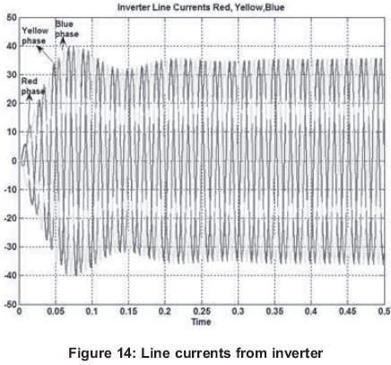
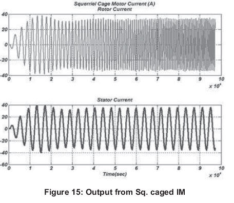
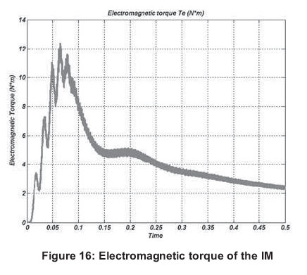
When connected via a balanced three-phase resistive load, the line current values generated are shown in Figure 14. Figure 15 indicates both the rotor and stator current of the induction motor, which after 0.012sec, the transients die down to state steady current of about 33 A. Figure 16 indicate the electromagnetic torque of the squirrel cage induction motor that the hybrid source was used to supply.
5. Conclusion
With the high demand of energy in this part of the world, this paper is presenting an alternative to be used by the remote areas in Nsukka, south-eastern part of Nigeria. As indicated, the availability of solar irradiance and wind speed in this part of the country is good enough to make the hybrid give high yield. Similarly, from the simulation result, the paper suggests that even mobile base stations, hospitals and hotels can start to make use of hybrid solar-wind generations.
This kind of energy generation can work effectively either as a single-phase supply or three-phase supply, in which case appliances of either single or three-phase can be used effectively. From the result of the simulation, it is observed that with little increase in the capacity of the wind turbine as well as number of PV panels, many homes can be covered. Since the power obtained from wind generation adds to the power from the PV system thereby improving the quantity of power available for the masses to use; the hybridized system if implemented will boost availability of power in the area. This paper therefore appeals to government and private investors to explore this means of power generation to help ameliorate the suffering of the poor masses in this part of the country as regards to inadequate power supply.
References
Adaramola, M. S. & Oyewola, O. M. (2011). Wind Speed Distribution and Characteristics in Nigeria, Asian Research Publishing Network Journal of Engineering and Applied Sciences, Vol. 6, No. 2. [ Links ]
Ahmed, M. H; Wael, A. F. & Osama, A. M; (2011). [ Links ]
Modelling and control of Direct driven PMSG for ultra large wind turbines, World Academy of Science, Engineering and Technology 59, [ Links ]
Ajao, K.R., Oladosu, O.A. & Popoola, O.T. (2011). Using Homer Power Optimization Software for Cost Benefit Analysis of Hybrid-Solar Power Generatio Relative To Utility Cost in Nigeria, IJRRAS 7 (1) http://www.arpapress.com/Volumes/Vol7Issue1/IJR-RAS_7_1_14. [ Links ]
Anandavel, P, Rajambal K. & Chellamuthu, C. (2005). Power optimization in a Grid- connected wind energy conversion system, IEEE Conf PEDS, pp.16171621. [ Links ]
Caisheng, W. & Nehrir, M. H. (2008). Power Management of a Stand-Alone Wind/Photovoltaic/Fuel Cell Energy System, IEEE Transactions on Energy Conversion, Vol. 23, No. 3. [ Links ]
Chiemeka, I. U; & Chineke T. C. (2009). Evaluating the global solar energy potential at Uturu, Nigeria, International Journal of Physical Sciences. Vol. 4 (3), 115-119. [ Links ]
Heier, S. (1998). Grid Integration of Wind Energy Conversion Systems, Hoboken, NJ: Wiley. [ Links ]
Hossein, K.D. (2012). Analysis and Control of a Microgrid with Converter Fed Distributed Energy Sources, PhD Thesis, Centre for Energy Systems Research, Tennessee Technological University, Cookeville, USA. [ Links ]
Monica C., Santiago A. & Juan C. B. (2006). Control of Permanent-Magnet Generators Applied to VariableSpeed Wind-Energy Systems connected to the Grid, IEEE Transaction on Energy Conversion, Vol. 21, No. 1, 130- 135. [ Links ]
NASA (2013). http://eosweb.larc.nasa.gov/. [ Links ]
Parita G., Dalwadi & Chintan R Mehta (2012). [ Links ]
Feasibility study of Solar-wind Hybrid power system, International Journal of Emerging Technology and Advanced Engineering Website: www.ijetae.com (ISSN 2250-2459, Volume 2, Issue 3). [ Links ]
Sambo, A.S. (2006). Electricity from Renewable Energy Resources For Remote Locations: A Case For Solar and Wind Energy, Keynote Address at the One- Day National Workshop on Solar and Wind Electricity for Remote Locations, held at the Niger Delta Wetlands Centre, Yenagoa, Bayelsa State. [ Links ]
Sambo, A.S. (2009), Strategic Developments in Renewable of Nigeria, International Association for Energy Economics, 15-19. [ Links ]
Yerra, S. R A., Jaya L, & Mostafa, K. (2012). Modelling and Control of Hybrid Photovoltaic-Wind Energy Conversion System, International Journal of Advances in Engineering & Technology, Vol. 3, Issue 2, 192-201. [ Links ]
Received 12 June 2013
Revised 30 May 2014

