


Serviços Personalizados
Artigo
 Inglês (pdf)
 Artigo em XML
 Referências do artigo
Indicadores

Links relacionados
-
 Citado por Google
 -
 Similares em Google
Compartilhar

 Permalink
Journal of Energy in Southern Africa
versão On-line ISSN 2413-3051
versão impressa ISSN 1021-447X
J. energy South. Afr. vol.25 no.2 Cape Town Mai. 2014
Design of a low voltage DC microgrid system for rural electrification in South Africa
Gilbert M Bokanga; Atanda Raji; Mohammed TE Kahn
Department of Electrical Engineering, Cape Peninsula University of Technology, Cape Town, South Africa
ABSTRACT
This project entails the design of a low voltage DC microgrid system for rural electrification in South Africa. Solar energy is freely available, environmental friendly and it is considered as a promising power generating source due to its availability and topological advantages for local power generation. Off-grid solar systems are perceived to be a viable means of power delivery to households in rural outlying areas in South Africa as solar panels can be used almost anywhere in the country. The design presented in this paper is based on the power demand estimation, photovoltaic panel selection, battery sizing and wire selection for the distribution system.
Keywords: battery storage, DC loads, photovoltaic panel and simulation
1. Introduction
Our electric power system was design to move central station alternating current (AC) power, via highvoltage transmission lines and lower voltage distribution lines, to householders and businesses that used the power in incandescent light, AC motors, and other AC equipment. But, extending the electric grid to remote rural areas is uneconomical to carry out.
Increases in global energy costs, coupled with the warming of the earth's atmosphere due to greenhouse gas, are energizing a worldwide call for clean and efficient energy sources and architectures. On the other hand, globally over 1.3 billion people are without access to electricity (IEA, 2011). Most of them live in rural and remote areas of developing countries, with a more dispersed population density; many of whom are either or below the poverty line. South Africa, for its part, has 12.3 million people without access to electricity (Weo, 2011). Meanwhile, there is an outburst of interest in the use of renewable energy source to reduce greenhouse gas emissions. Renewable energy generation typically produces DC power, making it a viable distributed source for the low voltage DC microgrid system which is viewed as the best solution of power delivery to households in outlying areas where the utility grid is out of reach.
This project entails the design of a stand-alone low voltage DC microgrid system to power a fully DC single house in outlying areas. When considering the electrification of rural areas it is important to design systems that are reliable and require little maintenance as in these areas frequent repairs and replacements might not be easy. Efficient and low power consumption DC home appliances that meet the basic needs of a simple house are considered first power demand estimation and from that a simplified solar system which consists of a PV panel, MPPT charge controller, battery and wires, is designed as a low voltage DC microgrid system to supply sufficiently the energy demand.
2. Background
Much research has been carried out into many aspects of rural electrification. One of the main aspects for the slow pace of rural electrification is simply the enormous cost associated with extending electricity grids to rural areas or establishing isolated mini power systems for rural communities (Mutale et. al, 2007). South Africa is a large country and has many rural areas. There is always no
Electrification of these areas requires new and cheaper technologies. It is more viable to directly use the power generated by a distributed renewable energy source nearby. This eliminates the enormous cost associated with extending electricity grids. Moreover, 12V (or 24V) DC appliances are relatively inexpensive in the concept when compared to AC appliances as they don't require buck converters to step down the 230V AC to 12V (24V) DC required by most of the appliances.
3. System design
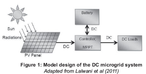
Hybrid renewable energy systems have been accepted as possible means of electrifying rural outlying areas where it is too expensive to extend the grid to supply them. As stipulated in the introduction, the system is intended to power households, and it must be cost effective; therefore, only solar energy system is retained. Figure 1 shows the overview of the low voltage DC microgrid system.
3.1 Loads selection and energy demand estimation
The 12V DC loads in Table 1 have been selected.

From Table 1, daily energy demand can be estimated. Table 2 shows daily energy consumption.
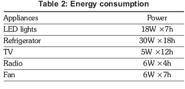
The energy consumption estimated in Table 2 gives a total daily average of 792Wh for a summer day.
3.2 Photovoltaic generator
A photovoltaic (PV) generator is the whole assembly of solar cells, connections, protective parts, supports etc. (Gonzalez, 2005). A photovoltaic (PV) generator converts sunlight energy into electricity. The energy produced by the solar system is reliant on climatic conditions.
A photovoltaic system consists of cells at a basic element level. These cells can be connected together in series to form modules (or Panels). Figure 2 shows a moderate model of a PV cell used in this paper.
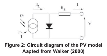
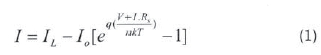
This model consists of a current source (IL), a diode (D), and a series resistance (Rs). The net current of the cell is the difference of the photocurrent, IL and the normal diode current Io; the model included temperature dependence of photocurrent IL and the saturation current of the diode Io. The equations which describe the I-V characteristics of the cell are (Gonzalez, 2005):
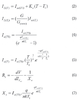
Where:
IL is the photo generated current (A);
I is the net cell current (A);
Io is the reverse saturation current of diode (A); q is the electron charge (1.602x10⁻¹⁹C);
V is the cell output voltage (V);
Rs is the resistance inside the cell (Q); n is the diode ideality factor (takes value between 1 and 2); k is the Boltzmann's constant (1.381x10⁻²³J/K);
T is the cell temperature in Kelvin (K);
T1 is the cell temperature at the Standard Test
Condition (STC), given as 25°C or 298K;
Isc(T1) is the short circuit current (A) at T1;
Ko is the temperature coefficient of Isc (%/oC);
G is the irradiance (W/m2);
G(nom) is the normalized value of irradiance at STC (1000W/m2);
Voc(T1) is the open circuit voltage of the cell at T1 (V).
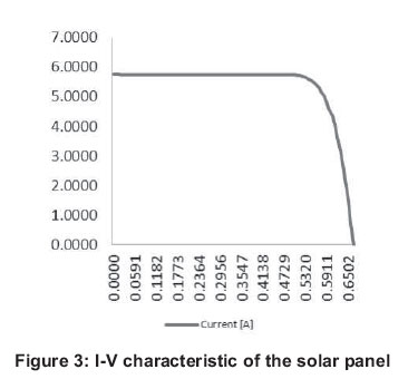
The Matlab script used to compute the equation (1) of the I-V characteristics is the Photovoltaic Module in Matlab by Gonzalez (Gonzalez, 2005). A typical I-V characteristic of the solar panel is shown in Figure 3. The P-V characteristics of the solar panel at two different atmospheric conditions are shown in Figure 4.

Koutroulis et al (2006) present the following methods of calculating the power of the PV panels at the specified temperature and the irradiance:

Where:
Ns is the number of series PV panels;
Np is the number of parallel PV panels;
Voci is the open circuit voltage at the specified temperature and irradiance;
Isci is the short circuit current at the specified temperature and irradiance;
FF is the fill factor of the panel;
Isc is the short circuit current at STC;
Ko is the temperature coefficient for short circuit current;
Tc is the calculated temperature;
T1 is the STC temperature at 25°C;
G is the irradiance;
Gnom is the irradiance at STC given as 1000W/m2;
Kv is the temperature coefficient for open circuit voltage;
T is the PV operating temperature;
NCOT is the Nominal Cell Operating Temperature.
The peak power for PV sizing is calculated as:

With:
Where:
Ed is the daily energy demand;
ηΤ is the product of component efficiencies;
η1 is the wiring efficiency (typically 90%);
η2 is the charge controller efficiency (90%);
η3 is the battery efficiency (typically 90%).
In the power versus voltage curve of a PV panel, there exists a single maxima of power (peak power corresponding to a particular voltage and current). The efficiency of the solar PV panel is low at about 13%. Since the panel efficiency is low it is desirable to operate the panel at the maximum power point so that the maximum power can be delivered to the load under varying temperature and irradiation conditions. This maximized power helps to improve the use of the solar PV panel. A maximum power point tracker (MPPT) extracts maximum power from the PV panel and transfers that power to the load.
3.3 Battery storage and controller
Because of the intermittent solar irradiation characteristics, which highly influence the resulting energy production, the major aspects in the design of the PV systems are the reliable power supply of the consumer under varying atmospheric conditions. Therefore, a means of energy storage must be implemented in the design of a stand-alone solar system, and will be used to power the loads during night hours and cloudy days.
Cell batteries are currently the most used form of energy storage in the solar system. Lead acid batteries are the one considered in this paper as they are the cheapest and most popular.
When sizing a battery, two major parameters must be taken into consideration, the State of Charge (SOC) and the Depth of Discharge (DOD). The battery, with total nominal capacity Cn (Ah), is permitted to discharge up to a limit defined by the maximum permissible depth of discharge DOD (%), which is specified when designing the system. Koutroulis (et. al., 2006) calculates the capacity of the battery at a point in time, t, as follows:
Where C (t), C (t-1) is the available battery capacity (Ah) at hour t and t-1, respectively, ηΒ=80% is the battery round-trip efficiency during charging and ηΒ=100% during discharging, VBUs is the DC bus voltage (V), PB(t) is the battery input/output power and At is the simulation time step, set to Δt=1h.
The size of battery storage can be calculated as follow (Zakaria et al, 2008):

Where:
TDWU is the daily-hours used;
AD is autonomy day (1< AD < 5).
The controller is sized either with equation (16) or equation (17):

Where:
Isc is the PV short-circuit current;
Fsafe is the safety factor;
Cn is the rated capacity of the battery; t is the minimum amount of hours of operation.
3.4 Distribution system
Figure 5 shows the simplified distribution system of the DC microgrid system. The wire sizing has to comply with the South Africa National Standard (SANS) on the wiring of premises.
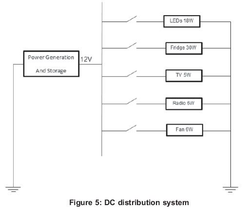
6 mm2 for the generation and storage side, and 2.5 mm2 for the distribution side will allow an acceptable tolerance of voltage drop for this low voltage system, refer to SANS 10142.
4. Simulation results
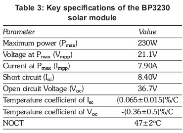
The BP solar BP3230T was selected based on the power demand and climatic conditions of the area retained for the simulation purpose. The BP3230 has 60 series connected polycrystalline silicon cells. The key specifications are shown in Table 3.
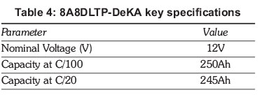
The 8A8DLTP-DEKA lead acid was selected as a means of energy storage. The key specifications are shown in Table 4.
To extract utmost power from the solar PV panel, the EPSOLAR tracer 2215RN has been selected as a MPPT solar charge controller. This MPPT solar charge controller has a peak conversion efficiency of 97% and a high tracking efficiency of 99%.
The climatic data of Mthatha in the Eastern Cape Province is used in this paper for simulation. The hourly temperature data was obtained from the South Africa Weather Service (SAWS) and the hourly solar irradiance data is provided by Helioclim through SoDa website. An extract of daily average of sun irradiance and temperature over a summer day and a winter day was used to simulate the power generated by the PV panel.
The figures show the evolution of the power demand estimation and the power generated by the as well as the SOC of the battery. Figures 5 and 6 show the results of simulation during a summer day. Figures 8 and 9 show the simulation results during a winter day.
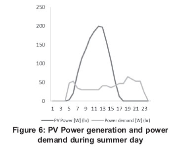
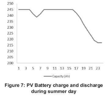

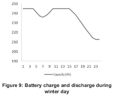
From the results of simulation, we can see that the PV panel can sustain the power demand, and the excess will be stored in the battery and will be used during no sunlight period. Also, the discharge of the battery is above the two set minimum SOC (40% and 50%).
5. Conclusion
The design of the low voltage DC microgrid system presented in this paper offers a simplified solar system as a means of power delivery to households in rural outlying areas. The importance and need for the use of renewable energy and cheaper technology in rural outlying areas were highlighted. A selection of energy efficient appliances based on the low-energy consumption restriction was presented. The proper sizing of the photovoltaic panel, the battery and the MPPT controller has been developed as well as the wires sizing. The simulations have been carried out and the results presented show the efficacy of the designed system. Further work could include a low-energy cooking device and more detailed modelling of the system components.
Acknowledgment
I would like to thank everyone who helped me with this project, friends and most of all to my supervisor Mr. Raji.
References
BP Solar BP3230T-230W Polycrystalline Photovoltaic Module Datasheet 2010. Engel, SB47F-G4-W Spec sheet, http://www.engelaustralia.com.au/upload/data_sheets/sb47f.pdf, Last accessed 5 May 2012. [ Links ]
EPSOLAR, Tracer-2210RN/2215RN, http://voile.org/panneaux_solaires/Tracer-2210RN.pdf., Last accessed 6 July 2012. [ Links ]
Gonzalez-Longatt, F.M. (2005). Model of Photovoltaic Module in MatlabTM, II CIBELEC 2005. [ Links ]
IAE, World Energy Outlook (2011). New Electricity access Database, http://www.worldenergyoutlook.org/WEO-2011newElectricityaccessDatabase, Last accessed 3 July 2012. [ Links ]
IEA (2011). Energy for all, Financing access for poor, OECD/IEA, Oslo, http://www.iae.org/papers/2011/weo2011energyfor.pdf . Last accessed 3 July 2012. [ Links ]
Koutroulis, E. D. Kolokotsa, D A. Potiraki, A.S. and Kalaitzakis K. (2006). Methodology for optimal sizing of stand-alone photovoltaic/wind-generator systems using genetic algorithms, Solar Energy, Vol. 80, No.9, pp. 1072-1088, 2006. [ Links ]
Lalwani, M., Kothari, D.P and Singh, M. (2011). Size optimization of stand-alone photovoltaic system under local weather conditions in India, International Journal of Applied Engineering Research, DINDIGUL, Vol. 1, No. 4, 2011. [ Links ]
MK Battery, 8A8DLTP-DEKA, http://www.mkbattery.com/images/8A8DLTP-DEKA.pdf, Last accessed 3 June 2012. [ Links ]
Mutale J., Gaunt C.T. and. Konjic, T. (2012). Electricity Service requirements in rural areas for domestic consumption and for productive use and services, Working Group C6-13 Rural Electrification Top#A, CIGRE, COLL 2007, http://www.uct.ac.za/staff/gaunt/LangkawiA2.pdf, Last accessed 5 July 2012. [ Links ]
Phocos, Datasheet_FR_1/1_e2010-04-01 , http://www.growes.ca/Docs/Phocos%20Product%20Catalog%202011.pdf, Last accessed 5 May 2012. [ Links ]
Phocos AG, Product Catalogue 090512, http://www.gdgreenergy.com/images/Product_Catalog.pdf, Last accessed 5 May 2012. [ Links ]
Sangean, PR-D7 AM/FM-Stereo Digital Tuning radio receiver-Instruction Manual, http://ccrane.com/instruction-manuals/sangean-prd7.pdf, Last accessed 5 May 2012. [ Links ]
SANS 10142-1: 2006-SABS, http://www.sabs.co.za/content/uploads/files/SANS10142-1_06-05-12_wp_JH_Amdt%205__Use%20only_.pdf, Last accessed 6 August 2012. [ Links ]
SANS 10142-1-SABS, http://www.ameu.co.za/library/industry-documents/./img/revistas/jesa/v25n2/SANS10142-1Amdt8.pdf, Last accessed 6 August 2012. [ Links ]
S. King Company, RP73002 Road Pro 10 inch 12 volt Fan, http://www.skingcompany.com/Convenience-RP73002_Road_Pro-P271.aspx, Last accessed 5 May 2012. [ Links ]
SoDa, Time Series of Solar Radiation Data, http://www.soda-is.com/eng/services/services_radiation_free_eng.php, Last accessed 6 August 2012. [ Links ]
Walker G. (2000). Evaluating MPPT converter topologies using MATLAB PV model, Australasian Universities Power Engineering Conference, AUPEC'00, Brisbane, 2000. [ Links ]
Zakaria, Z.A. Chen, B. and Hassan, M.O. Modeling of Photovoltaic Power Plants, in IEEE 2008 International Conference on Electrical Machines and Systems, Wuhan, 2008, pp. 3835-3839. [ Links ]
Received; 8 October 2012; 12 May 2014

