


Servicios Personalizados
Articulo
 Inglés (pdf)
 Articulo en XML
 Referencias del artículo
Indicadores

Links relacionados
-
 Citado por Google
 -
 Similares en Google
Compartir

 Permalink
Journal of Energy in Southern Africa
versión On-line ISSN 2413-3051
versión impresa ISSN 1021-447X
J. energy South. Afr. vol.25 no.1 Cape Town ene. 2014
Numerical simulation of atmospheric boundary layer and wakes of horizontal-axis wind turbines
Ali M AbdelSalam; Ramalingam Velraj
Institute for Energy Studies, Anna University, Chennai, India
ABSTRACT
Simulations of wind turbine wakes are presented in this paper using the three-dimensional Reynolds-Averaged Navier-Stokes (RANS) equations employing the k-ε turbulence model appropriately modified for the atmospheric flows. The actuator disk approach is used to model the action of the turbine rotor. Modified formulations of the inlet conditions and the wall functions are used to allow consistency between the fully developed atmospheric boundary layer (ABL) inlet profiles and the wall function formulation. Results are presented and compared with three wind turbines running under neutral atmospheric conditions. The results demonstrate that the accurate simulation of the atmospheric boundary layer applying enhanced inlet conditions and wall function formulation consistent with the k-ε model can give very useful information about the wakes, directly contributing to the accurate estimation of the power of the downstream turbines.
Keywords: atmospheric boundary layer, wake, wind turbine, actuator disk
1. Introduction
The wind turbine wake is characterized by stream-wise velocity deficit, which leads to less power available for the downstream turbines. It also causes high turbulence levels which can give rise to high fatigue loads. Thus, it is important to predict the effect of these wakes so as to maximize the power output of a wind farm. To predict the wakes in the near and far wake regions of a wind turbine, the representation of the rotor forces with a computationally inexpensive method is necessary. Further, modelling the equilibrium atmospheric boundary layer (ABL) in the computations is important as it is a precondition for modelling the flow of wind turbines.
The actuator disk method, which is a simplification in the representation of the turbine rotor, allows for the gross effects of the rotor to be captured with an appreciable decrease in computing time as the blade geometry is not resolved. It was intensively used by Masson and his team for wind turbine simulations (Masson et al., 2001; Smaili and Masson, 2004; Masson and Smaili, 2006). Despite its simplicity, it is often a useful representation to reproduce wind deficits and wake losses. However, it bears the assumption that the rotor is just acting as a momentum sink without any further influence on the Reynolds stress tensor. Using the actuator disk model, along with the standard k-ε model failed to predict the wake behaviour accurately, and a significant underestimation of the near wake deficit compared to the measurements was observed (Rethore, 2009; Rados et al., 2009; Cabezon et al., 2009).
Since the dissipation rate equation is highly empirical, improvement in model performance is usually achieved by modifying the dissipation rate ε equation (Hanjalic and Launder, 1980). Chen and Kim (1987) have taken a general approach, testing for several problems; their approach yielded much better results than had the standard k-ε model. El Kasmi and Masson (2008) used a numerical model based on the actuator-disk model, combined with the Reynolds-Averaged Navier-Stokes (RANS) equations, to calculate the flow in the vicinity of the turbine. An extra term has been added to the ε equation in the near wake. The method proposed has been shown to yield much better results than the standard k-ε model. Despite the improvement, the term added to the ε equation has a constant that is to be determined through the experimental data and a single optimum value for the constant cannot be extracted. On the contrary, the optimum values for each case are so far from each other that they cannot define an optimum constant value, even for neutral conditions (Prospathopoulos et al., 2011).
Atmospheric turbulence has a major contribution to the turbulence in the wake of a wind turbine and within a wind park. Therefore, modelling equilibrium ABL in computational fluid dynamics (CFD) is an important aspect in the simulations. The practical simulations of the ABL flows are often carried out using RANS in combination with two-equation k-ε turbulence models. This model, with standard model constants, has been applied over a wide range of turbulent flow problems. Crespo et al. (1985) have proposed values for the model constants appropriate for the neutral atmospheric boundary layers. As far as the inlet profiles for ABL simulations are concerned, profiles by Richard and Hoxey (1993) were usually used as inlet conditions. They proposed fully developed inlet profiles of mean velocity, turbulent kinetic energy and dissipation rate for neutral stratification conditions. However, the inflow boundary conditions should satisfy the turbulence model employed. The inflow conditions proposed by Richard and Hoxey are not accurate to satisfy these conditions. Furthermore, the assumption of constant turbulent kinetic energy k proposed by Richard and Hoxey contrasts to wind-tunnel and full scale measurements, where a decrease of k with height is observed. It is mentioned by Richards and Quinn (2002) that in some published CFD studies, the combination of the inlet conditions, the turbulence model and the ground roughness resulted in a boundary layer which changed considerably between the inlet and the object under investigation. Improper ABL modelling can yield large errors in the numerical results. Yang et al. (2009) proposed a new set of inflow turbulence boundary conditions as an approximate solution to the standard k-ε model transport equations. The capability of these boundary conditions to produce equilibrium ABL was demonstrated in their numerical simulations.
There is still a gap between CFD results and wake measurements, and the transition to the 3D CFD computations using more improved realistic boundary conditions to simulate the atmospheric boundary layer seems a logical extension for better wind farm and turbine design. In the present paper, a numerical method based on the actuator-disk model, combined with RANS and employing a k-ε turbulence closure suitably modified for neutral atmospheric boundary layer flow, has been used to simulate the wakes of a wind turbine. The rotor disk is simulated as a momentum sink through the actuator force, which is related to a constant thrust coefficient over the rotor area. A set of enhanced inflow turbulence boundary conditions proposed by Yang et al., (2009) as an approximate solution to the standard k-ε model transport equations were conducted.
2. Theory
2.1 Rotor modelling
The wind flow is governed by the incompressible steady three-dimensional Navier-Stokes equations. The wind turbine rotor is simulated as a momentum sink through the actuator force, which represents the effect of the rotor on the flow, according to:

2.2. Turbulence formulation
The standard k-ε model proposed by Jones and Launder (1972) appropriately modified for the atmospheric flows is considered in the present simulation. The transport equations for the turbulent kinetic energy k and its dissipation rate ε are written as:
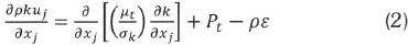
and
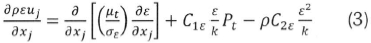
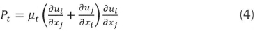
where uj is the velocity vector, σk, and σε are the turbulent Prandtl numbers for k and ε, respectively. C1ε, C2ε are constants. Pt is the production of the turbulence kinetic energy.
The turbulent (eddy) viscosity µt is computed according to:

where Cµ is a constant.
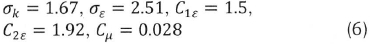
A constant ratio of σκ/σε - 1.5 was recommended by Poroseva and Iaccarino (2001) for practical purposes instead of the standard values. The value of the coefficient C1ε = 1.44, which depends on the type of flow and on the Reynolds number, has large effects on the calculated results (Poroseva and Iaccarino, 2001). There are some formulations available in the literature to define the value of C1ε as function of various flow and geometrical parameters (Durbin 1995). Based on this information and the relationship between the constants in the standard k-ε model (Richards and Hoxey, 1993), the modified turbulence model constants used by Yang et al., (2009) are:
The fully developed inlet profiles of mean velocity, turbulent kinetic energy and dissipation rate for neutral stratification conditions proposed by Yang el al. (2009) are implemented. The mean velocity profile is represented by the logarithmic law as:
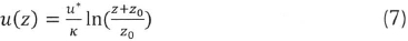
Where, u* is the friction velocity, u* = √τ0/ρ and τ0 is the surface shear stress, κ is the von Karman constant (equal to 0.42) and z is the vertical distance, and z0 is an aerodynamic roughness length that corresponds to the site topology. The inflow boundary condition of the turbulent kinetic energy is represented by:
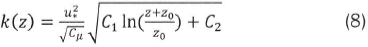
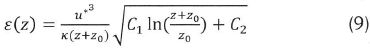
Where C1 and C2are constants that can be determined from experimental data.
The dissipation rate profile at inlet is given by:
2.3 Wall function formulation
The Richards and Hoxey (1993) boundary condition has been implemented at the wall to specify velocity, turbulent kinetic energy and turbulent dissipation rate consistently with the inlet profiles and turbulence model. The production of turbulent kinetic energy at the wall is not integrated over the first cell height but computed at the first cell centroid (Parente et al, 2011).
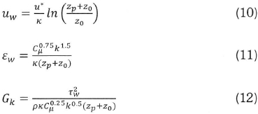
Where zp is the distance between the centroid of the wall-adjacent cell and the wall.
3. Computational domain
A side view of the computational domain considered for analysis is shown in Figure 1. The rotor disk that represents the wind turbine is located 2 D downstream of the inlet boundary (D is the rotor diameter) and the centre of the disk is considered as the origin point. The domain is extended 25 D downstream of the turbine in the axial direction and 8 D in the spanwise direction.
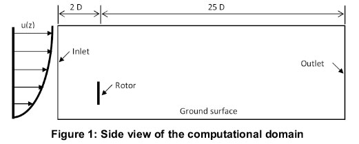
The static pressure at the outlet boundary of the domain is considered to have a zero value relative to the atmospheric pressure. The side boundaries are far enough from the wind turbine, and are considered as symmetry boundary conditions. The height of the domain above the rotor hub is 4 D. The computational domain was meshed by ICEM with a mixed three-dimensional mesh, to carry out the wind turbine fluid flow simulation. A fine mesh is constructed in the area of the wind turbine rotor disk with grid spacing close to 0.025 D, and the mesh grows in size outward from the rotor surface to the extended domains.
4. Solution methodology
The complete set of fluid equations consists of the continuity equation, the three momentum equations for the transport of velocity, and the transport equations for k and ε. To solve the RANS equations in the near and far wake regions of the wind turbines, the wind turbines are modelled as momentum absorbers, through the actuator disk approach, by means of their thrust coefficient.
In this paper, CFD is applied using the commercial multi-purpose CFD solver FLUENT. The inlet conditions described in section 2.2 are implemented in the solver using user defined functions UDF. A special treatment is conducted to account for the wall function formulation, as described in section 2.3. The three-dimensional fluid flow equations are solved using control-volume-based technique for converting the governing equations into algebraic equations, to be solved numerically. The solution algorithm adopted is SIMPLE, and the first-order upwind scheme is used for all the dependent properties to avoid convergence problems associated with higher order schemes (Ameur et al., 2011). The results were extracted from the computational domain along different sections downstream of the wind turbine rotor.
5. Results and discussion
The results presented in this section are intended to demonstrate the ability of the proposed model to accurately predict the wind turbine wakes by comparing the numerical predictions with the measurements of three wind turbines concerning neutral atmospheric conditions.
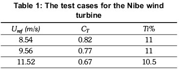
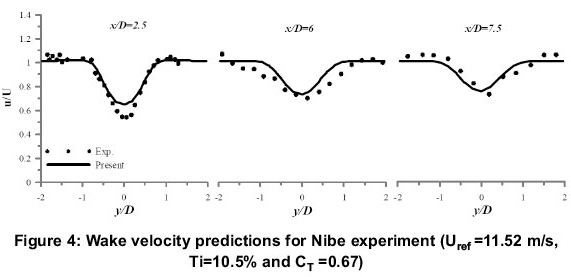
The first comparison is the three-blade Nibe-B 630-kW wind turbine operating at a rotational speed of 33 rpm with a 40 m diameter located at a hub height of 45 m (Pederson and Nielson, 1980; Taylor et al., 1985). The computations are carried out at different conditions including the freestream wind speed at hub height Uref, the free stream turbulence intensity Ti, and the thrust coefficient CT of the wind turbine. The cases studied corresponding to the measured data for the Nibe wind turbine are illustrated in Table 1.
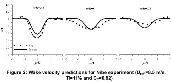
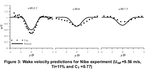
Figures 2, 3 and 4 compare the results obtained using the present methodology with the measurements for different inflow conditions. It presents the horizontal profiles of the axial velocity u/U in a centreline passing through the centre of the rotor at hub height at distances of 2.5, 6 and 7.5 D downstream of the wind turbine. In the near wake (x/D=2.5), the present simulation slightly over-predicts the velocity deficit, but captures the spreading of the wake observed in the experimental data and predicts the correct trough-like profile. At the distance of 6 D downstream the turbine, the predictions produce a relatively thin shear layer. However, the evaluated velocity deficits at the centre of the wake match well with the measurements. Due to the turbulent diffusion, the shear layer thickness increases with downstream distance of 7.5 D, which causes the wake recovery. The higher thrust coefficients produced at lower wind speeds causes the numerical results to give slow wake recovery.
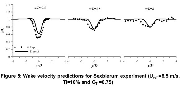
The second case is the Sexbierum wind farm (Cleijne, 1993) which is composed of 18 W/Ts with 310 kW rated power, 30 m diameter and 35 m hub height, positioned in three parallel rows of six wind turbines. In addition to the wind speed, the turbulence intensity was measured in different positions located in the wake of the wind turbine. During the experiment, the free stream conditions at hub height were Uref = 8.5 m/s and Ti = 10%. For this free stream wind speed, the thrust coefficient of the turbine was estimated to be CT = 0.75. The numerical simulations provide a good agreement with the measurements, as shown in figure 5. However, the wake deficit at x/D=2.5 downstream the wind turbine is slightly underestimated for this case also.
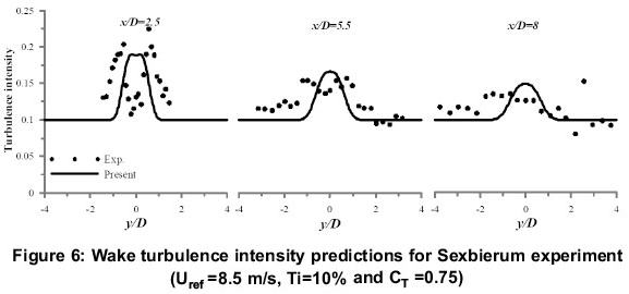
The turbulence intensity predictions of the Sexbierum wind turbine are illustrated in Figure 6. The characteristic double shoulder pattern is not reproduced by the predictions. Measurements of the turbulence intensity exhibit a different pattern at the 2.5 D distance. Higher peaks appear at the regions of mixing flow caused by the rotation, while much lower levels exist in the inner region of the wake, almost reaching the undisturbed value of turbulence intensity. It seems that the different characteristics of the wind turbine have an influence in the near-wake turbulence pattern. These differences attenuate as the distance from the wind turbine increases.
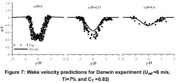
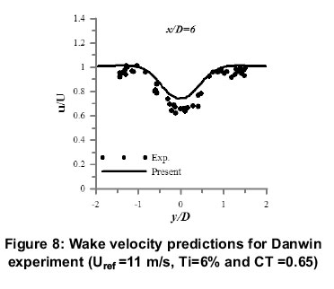
The last case is the three-blade Danwin 180-kW wind turbine, operating at a rotational speed of 42 rpm with a rotor diameter of 23 m and located at a hub height of 31 m (Magnusson et al., 1996; Magnusson and Smedman, 1999). Figure 7 depicts the predictions from the simulation of the Danwin wind turbine for wind speed of 8 m/sec. There is good agreement between the obtained flow velocity, and the available experimental results.
The results of the above wind turbine are also tested for the inflow wind speed of 11 m/sec, for which the experimental data are available at 6.2 D downstream the turbine. It is seen from Figure 8 that, the results obtained from the numerical simulations are matching well with the experimental results.
6. Conclusions
In the present paper, three-dimensional numerical simulations of flow around horizontal-axis wind tur- bines were conducted. The proposed method was tested by comparison of the predictions and the experimental measurements of three wind turbines. The rotor was modelled using the actuator disk approach and the turbulence was modelled using k-ε model appropriate for the neutral atmospheric stratification.
For a more realistic representation of the flow field, a set of enhanced inlet conditions are used to satisfy the k-ε turbulence model equations. An additional requirement for modelling equilibrium ABL is the correct modelling of the ground roughness. A modified wall function formulation consistent with the inlet profiles of the neutral atmospheric flow was conducted.
Comparison of the results obtained from the numerical analysis and the measurements indicates the capability of proposed approach of predicting the wind turbine wakes. There is good agreement between the flow velocity evaluated from the CFD analysis and the experimental results measured downstream the wind turbine. The characteristic double shoulder pattern of the turbulence intensity was not reproduced by the predictions. However, the peak values are in reasonable agreement. This suggests the need to model the atmospheric boundary layer accurately and its effect on the turbulence quantities to better understand the physical mechanisms that govern the wind turbine wakes.
References
Ameur, K., Masson, C. and Ecen, PJ. (2011). 2D and 3D numerical simulation of the wind-rotor/nacelle interaction in an atmospheric boundary layer, Journal of Wind Engineering and Industrial Aerodynamics, 99: 833-844. [ Links ]
Cabezon, D., Sanz, J., Marti I. and Crespo, A. (2009). CFD modelling of the interaction between the Surface Boundary Layer and rotor wake. Comparison of results obtained with different turbulence models and mesh strategies, In: European wind energy conference & exhibition proceedings, Parc Chanot, Marseille, France, 16-19 March 2009. [ Links ]
Chen, Y.S. and Kim, S.W. (1987). Computation of turbulent flow using an extended k-ε turbulence closure model, NASA Contractor Report. NASA CR-179204. [ Links ]
Cleijne, J.W. (1993). Results of the sexbierum wind farm; single wake measurements, TNO Report 93082, TNO Institute of Environmental and Energy Technology, The Netherlands. [ Links ]
Crespo, A., Manuel, F, Moreno, D., Fraga, E. and Hernandez, J. (1985). Numerical analysis of wind turbine wakes, Proceeding of Delphi Workshop on Wind Energy Applications Delphi, Greece, 15-25. [ Links ]
Durbin, P.A. (1995). Separated flow computations with the k-ï-v2 model, AIAA Journal, 33: 659-664. [ Links ]
El Kasmi, A. and Masson, C. (2008). An extended k-ï model for turbulent flow through horizontal-axis wind turbines, Journal of Wind Engineering and Industrial Aerodynamics, 96: 103-122. [ Links ]
Hanjalic, K. and Launder, B.E. (1980). Sensitizing of the dissipation equation to irrotational strains, Trans. ASME, 102: 34-40. [ Links ]
Jones, W.P and Launder B.E. (1972). The prediction of laminarization with a two-equation model of turbulence, Int. J. Heat and mass transfer, 15: 301-314. [ Links ]
Magnusson, M., Rados, K.G. and Voutsinas, S.G. (1996). A study of the flow downstream of wind turbine using measurements and simulations, Wind Engineering, 20: 389-403. [ Links ]
Magnusson, M. and Smedman, A.S. (1999). Air flow behind wind turbines. Journal of Wind Engineering and Industrial Aerodynamics, 80: 169-189. [ Links ]
Masson, C., Smaili, A. and Leclerc, C. (2001). Aerodynamic analysis of HAWTs operating in unsteady conditions, Wind Energy, 4: 1-22. [ Links ]
Masson, C. and Smaili, A. (2006). Numerical study of turbulent flow around a wind turbine nacelle, Wind Energy, 9: 281-298. [ Links ]
Parente, A., Gorlé, C., van Beeck, J. and Benocci, C. (2011). Improved k-ε model and wall function formulation for the RANS simulation of ABL flows. Journal of Wind Engineering and Industrial Aerodynamics 99: 267-278. [ Links ]
Pederson, B.M. and Nielson, P (1980). Description of the two Danish 630kW wind turbines, Nibe-A and Nibe-B, and some preliminary test results, DEFU, Denmark. In: Third International Symposium on Wind Energy Systems, August 26-29, pp. 223-238. [ Links ]
Poroseva, S. and Iaccarino, G. (2001). Simulating separated flow using k- ε model, Annual Research Briefs 2001, Centre for Turbulence Research, Stanford University. [ Links ]
Prospathopoulos, J.M., Politis, E.S., Rados K.G. and Chaviaropoulos, P.K. (2011). Evaluation of the effects of turbulence model enhancements on wind turbine wake predictions, Wind Energy, 14: 285-300. [ Links ]
Rados, K.G., Prospathopoulos, J.M., Stefanatos, N.Ch., Politis, E.S., Chaviaropoulos, PK. and Zervos, A. (2009). CFD modelling issues of wind turbine wakes under stable atmospheric conditions, In: European wind energy conference & exhibition proceedings, Parc Chanot, Marseille, France, 16-19 March 2009. [ Links ]
Rethore, P.E. (2009). Wind turbine wake in atmospheric turbulence, PhD Thesis, Aalborg University, Department of Civil Engineering, ISSN 1901-729. [ Links ]
Richards, PJ. and Hoxey, R.P (1993). Appropriate boundary conditions for computational wind engineering models using the k-ε turbulence model, Journal of Wind Engineering and Industrial Aerodynamics, 46 & 47: 145-153. [ Links ]
Richards, PJ. and Quinn, A.D. (2002). A 6m cube in an atmosphere boundary layer flow, part 2. Computational solutions, Wind and Structures, 5: 177-192. [ Links ]
Smaili, A. and Masson, C. (2004). On the rotor effects upon nacelle anemometry for wind turbines, Wind Engineering, 28 (6): 695-714. [ Links ]
Taylor, G.J., Milborrow, D.J., McIntosh, D.N. and Swift-Hook, D.T. (1985). Wake measurements on the Nibe windmills, In: Proceedings of Seventh BWEA Wind Energy Conference, Oxford, pp. 67-73. [ Links ]
Yang, Yi., Gu, M., Chen, S. and Jin, X. (2009). New inflow boundary conditions for modelling the neutral equilibrium atmospheric boundary layer in computational wind engineering, Journal of Wind Engineering and Industrial Aerodynamics, 97: 88-95. [ Links ]
Received 20 May 2013
Revised 17 December 2013

