


Serviços Personalizados
Artigo
 Inglês (pdf)
 Artigo em XML
 Referências do artigo
Indicadores

Links relacionados
-
 Citado por Google
 -
 Similares em Google
Compartilhar

 Permalink
Journal of Energy in Southern Africa
versão On-line ISSN 2413-3051
versão impressa ISSN 1021-447X
J. energy South. Afr. vol.24 no.4 Cape Town Abr. 2013
RESEARCH ARTICLE
Dirt analysis on the performance of an engine cooling system
Yashvir SinghI; Nishant Kr. SinghII
IMechanical Engineering Department, University of Petroleum and Energy Studies, Uttarakhand, India
IIMechanical Engineering Department, Hindustan College of Science and Technology, Uttar Pradesh, India
ABSTRACT
This present work looked at the effect of sand blocking the heat transfer area of the radiator and its effect on the engine coolant through the conduct of experiments and a mathematical model developed. The results indicated that the percentage area covered resulted in a proportional increase of the inlet and outlet temperatures of the coolant in the radiator. The mathematically model developed also predicted the experimental data very well. Regression analysis pointed out that every 10% increase area of the radiator covered with silt soil resulted in an increase of about 1.7oC of the outlet temperature of the radiator coolant. Similarly, using mud as a cover material, 10% of the area covered of the radiator resulted in an increase of about 2oC of the outlet temperature of the radiator coolant. Statistical analysis pointed to the fact that the result obtained for mud, silt and the mathematical model were not significantly different. Thus, irrespective of the type of material that blocks the radiator surface area, the coolant rises proportional of the radiator covered.
Keywords: radiator, silt, mud, coolant.
1. Introduction
When new engines are developed, they will be expected to operate under severe conditions and demanding load profiles as studied by Kem and Abros (1997), thus, increasing the demand of effective engine cooling systems. The automotive industry is continuously involved in a strong competitive market to obtain the best automobile design in multiple aspects. Some of the aspect includes performance, low fuel consumption, aesthetics, safety,- cheaper and low maintenance.
According to Oliet et al., (2007), the air-cooled heat exchangers found in a vehicle radiator, Air-Conditioning (AC) condenser, evaporator and charge air cooler, has an important role in its weight and also in the design of its front-end module. In addition, it has a strong impact on the car aerodynamic behaviour. Looking at these challenges, the design process is optimized to obtain the optimum design.
The high working temperatures of the internal combustion engine which are the cause of its high efficiency are at the same time a source of great practical challenge in construction and operation. Moreover, there are challenges in obtaining materials capable of continuously enduring the high temperatures to which the cylinder, piston and valves are subjected to, while at the same time retaining sufficient strength to withstand the high working loads (Pulkrabek, 1997). The maximum temperature attained during combustion is approximately equal to the melting point of platinum, and the temperature even of the exhaust gas is above that of melting point of aluminium. Thus, it is essential that heat be abstracted from the combustion chamber at a sufficient rate to prevent a dangerous temperature being reached. Unfortunately, it is quite impossible to prevent the hot gas from flowing over the metal surfaces. Excessive cooling also prevents proper vaporization of the fuel, leading to further waste. In addition, it may lead to dilution of the crankcase oil by un-vaporized fuel, which gets down past the piston. On the other hand, a high operating temperature changes weight and reduces volumetric efficiency (VE) on account of the excessive heating of the incoming charge. Consequently, there is reduction of output power.
Over the years there have been increasing demands on the engine cooling system of a car. This has been caused by a steady increase in engine output; combined with a reduction in the size of the cooling inlets and an increase in auxiliary components (Mudd, 1972). A water-cooling system is employed in almost every new car. The water coolant passes through the engine extract heat around the combustion chamber and dissipates the heat in the radiator. The radiator transfer heat from the coolant to the air flowing through the fins of the radiator. The air flowing is driven by a combination of the forward motion of the car and from a fan enclosed in a shroud attached to the radiator.
The basic requirement of a radiator is to provide a sufficiently large cooling area for transmission of heat from the coolant to the air. The construction of the centre of the radiator or core varies, but in general the water passages terminate at a header tank at the top of the radiator, and a smaller collecting or lower tank at the bottom. In addition to an opening which enables the cooling system to be topped up, the header tank allows for expansion and contraction of the coolant within the system (Kiatsiriroat, 2004). The trend towards low bonnet lines has led to the adoption by some vehicle manufacturers of a cross-flow radiator, the water tubes being placed cross-wise with a small collection tank at each side, and a separate header tank. The alternative to a cross -flow would be to have a large number of short vertical tubes, but this would increase the amount of soldering and hence the chance of leakage (Nuntapha and Kiatsiriroat, 2004).
The main objective of this research is to look at the critical quantification of dirt on the radiator and its effect on the engine performance. The focus will be to look at the effect of mud or silt on the radiator fins and its impact on temperature variation in the inlet and outlet of the radiator hoses. The study will look at the way forward to minimize overheating.
2. Materials
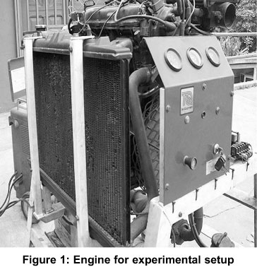
2.1 Engine
The engine used for the experiments was the four-cylinder four stroke engine shown in Figure 1. The engine is a water cooled engine with a tank capacity of 5.5 litres. It is a petrol engine which has a compression ratio of 9.8 to 1 and operates on the Otto-cycle.
2.2 Radiator
The radiator of the engine was a General Motors' serpentin-fin cross-flow type of size 65 mm x 35 mm in length and breadth respectively. The numbers of tubes were one row of 66 tubes with a thickness of 2 mm. The fins were copper made with a thickness of 0.5 mm, a height of 16 mm and spaced 3 mm apart.
2.3 Thermometer
Two different types of thermometers were used for the experiment. Two thermocouple probes were used to read the input and the output temperatures coolant in the radiator. The thermocouple was manufactured by Cola-Parma Instrument Company with model number 8110-10 and an accuracy of 0.10 oC. A mercury-in bulb thermometer was used to measure the ambient temperature.
2.4 Covering material
Two different soil types were used. Silt and clay soil were chosen for the experiment because of their ability to stick to the radiator surface area.
3. Experimental setup
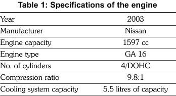
The specifications for the engine used are shown in Table 1. The engine was fitted with two thermocouple probes to read the inlet and outlet temperature of the water in and out of the radiator. The radiator was first cleaned to get rid of all particles trapped in the fins and on the engine. The rotational speeds of the engine and the fan speed were held constant throughout the experiment. The effective heat transfer area of the radiator was divided into ten (10) equal parts representing 10% of the effective heat transfer area. The effective heat transfer area was then partially covered with either mud or silt soil to the required percentage before running the engine. The engine was run for about fifteen (15) minutes to attain stable conditions before readings were taken.
For each set-up, three readings were taken at intervals of two minutes. After each experiment, the radiator was removed and washed to get rid of all the sand particles and then dried in open air. Each experiment was repeated three times according to the random sample technique adopted.
3.1Radiator heat transfer model
There are two common models available in the literature for analysing the heat transfer process in a radiator. The two methods are:
- Log mean temperature difference; and
- Effectiveness-Number of heat transfer units method.
In modelling, the radiator and the □-NTU was used because the focus of the work is on the outlet and inlet temperature of the water after the effective heat transfer area is then partially covered with either clay or silt soil to the required percentage before running the engine. The model was developed to predict the outlet temperature of the coolant from the radiator given the dimensions of the radiator, the flow rates of the fluids and the cooling load. In order to solve the analytical model, the following assumptions were made:
(i) Constant coolant flow rate and fluid temperatures at both the inlet and outlet temperatures, the system operated at a steady state
(ii) There were no phase changes in the coolant
(iii) Heat conduction through the walls of the coolant tube was negligible
(iv) Heat loss by coolant was only transferred to the cooling air, thus no other heat transfer mode such as radiation was considered
(v) Coolant fluid flow was in a fully developed condition in each tube
(vi) All dimensions were uniform throughout the radiator and the heat transfer of surface area was consistent and distributed uniformly
(vii) The thermal conductivity of the radiator material was considered to be constant
(viii) There was no fluid stratification, losses and flow misdistribution.
The relevant equations are given from equation 1 to 7.

The radiator core frontal area, Afr is given by:

Coolant tube frontal area, Afr,t is given by:

Fin heat transfer area, Af, is given by:

The total heat transfer area on air side, Aa is given by:

The total heat transfer area on coolant side, Ac is given by:

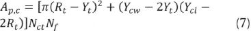
The total coolant pass area, Ap, c is given by:
The heat transfer rate in the radiator is given by:

Where Cmin = minimum heat capacity rate.
The radiator thermal efficiency ε is defined as the ratio of the actual transfer rate from the hot fluid (coolant) to the cold fluid (air) in a given radiator to the maximum possible heat transfer rate. It is expressed as:

The actual heat transfer balance equation at a steady state, which is defined in terms of energy loss on coolant side and energy gained on the air side is given by:

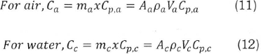
The heat capacity ratio is defined as the product of the mass flow rate and the specific heat of the fluid:
The heat capacity ratio is defined as the ratio of the smaller to the larger capacity rate for the two fluid streams and is expressed as:

Where Cmin is the smaller of Ca and Cc.

The heat capacity ratio is defined as the ratio of the smaller to the larger capacity rate for the two fluid streams and is expressed as:

Where Cmin is the smaller of Ca and Cc.

It follows therefore that the heat transfer rate is given by:

The number of heat transfer units (NTU) is the ratio of overall conductance UA to the smaller capacity rate Cmin:
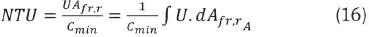
The radiator effectiveness is defined as a function of both the NTU and the Cr by
Based on the equations outlined, the model was developed using MATLAB.
4. Results and discussions
Results obtained from the running of the experiments and comparing them with results of the model developed follow.
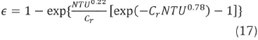
4.1 Mud as the cover material
As shown in Figure 2, the temperature of the coolant from the radiator increased with an increase in the area of the radiator covered. As the area covered increased, there was also a corresponding increase in the temperature of the coolant coming from the engine.
The highest temperature obtained for the coolant into the radiator was achieved when 100% of the radiator was covered. During the experiment it was noticed that the engine stopped running after a short time when the radiator was completely covered. This was due to the inability of the coolant from taking away enough heat from the walls of the engine thereby causing overheating and subsequently forcing the engine to stop running in order to prevent substantial damage to the engine.
At 80% coverage of the radiator, it was observed that the engine idling was not stable. The engine- vibrated excessively. The water within the expansion tank began to overflow and the coolant tube was also observed to be very hot.
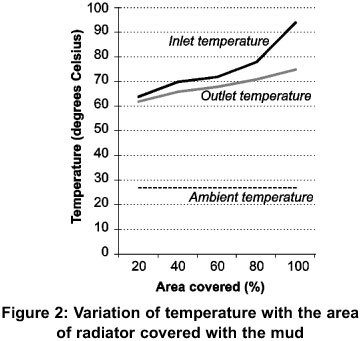
4.2 Silt as the cover material
As shown in Figure 3, the results obtained using silt as the covering material were identical to that of clay as covering material. It can be observed that as the percentage area covered increased, there was a corresponding increase in the outlet and inlet temperatures of the coolant fluid. When 80% of the radiator surface was covered, it was observed that the engine idling was not stable and the engine vibrated excessively. Also, the water within the expansion tank began to overflow just as it was observed when clay was used as the covering material. At 100% covering, the engine could not stay on and after a short time of running the engine stopped running. The highest inlet temperature of the coolant recorded was 74 oC and this was when100 % of the radiator surface was covered.
4.3 Discussions
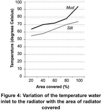
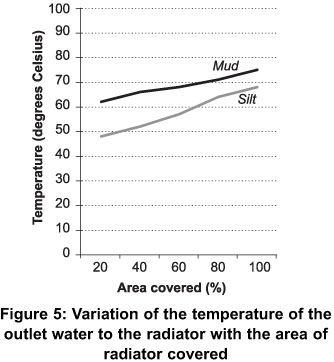
When results obtained using mud were compared to that obtained using silt as shown in Figures 4 and 5, it was observed that the coolant temperature in the radiator was higher when mud was used as the cover material than when silt was used. This could be explained by the fact that mud stuck better on the radiator surface than silt. Because silt is loose, pocket of air space was observed on the covered radiator surface. This resulted in some amount of air passing through the air spaces to aid in the cooling of the coolant to a lower temperature than when mud was used. Since less heat was removed from the coolant, the resultant temperature of the coolant obtained from the radiator was also found to be higher for mud than silt as shown in Figure 5 below.
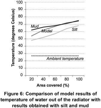
Also, when the result of the model was compared to the results obtained for the experiment as shown in Figure 6), it was observed that the model predicted the heat transfer phenomenon quite well. In spite of the many assumptions, it was observed that the temperature of the coolant from the radiator was comparable to results obtained for the experiments. The model predicted closely, the results obtained when clay was the covering material better than silt. This is perhaps due to the fact that clay was a better coverage material than silt as already mentioned. It was generally observed that as the area of the radiator covered was increased, the temperature of the coolant from the radiator also increased considerably. This can be explained by the fact that the effective heat transfer area was reduced, thereby limiting the quantity of air admitted through the radiator for purposes of cooling the coolant. In all cases this trend of increasing outlet temperature of the coolant from the radiator was observed. As shown in the Figure 6, the temperature of the ambient air was found to be relatively constant. This therefore did not significantly affect the rate of heat transfer because the air mass was almost constant just as the thermal properties of the air.
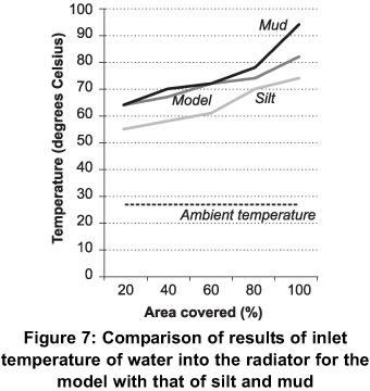
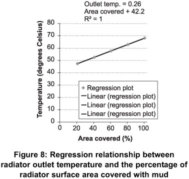
Comparing the temperature of the coolant into the radiator for three scenarios - the model, mud covering and silt covering, it can be observed in Figure 8 that the results obtained were similar. The model was able to predict the heat transfer process quite well. In all the three cases, the temperature of the coolant into the radiator increased as the area of the radiator covered also increased. This is due to the fact that when the surface area of the radiator is reduced by covering, less heat is taken out of the coolant, thus increasing the outlet temperature of the coolant from the radiator as observed. Since the coolant is not well cooled, it picks up heat from the engine which increases its temperature higher than expected before entering the radiator.
4.4 Regression and Anova analysis
Presented in Figures 8, 9 and 10 are the graphical regression relationships between the radiator coolant outlet temperatures and the proportion of the radiator surface area covered with mud, silt and Matlab simulation respectively. As expected, it can be seen that as the percentage of the radiator surface covered increases the outlet temperature of the radiator coolant increases.
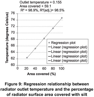
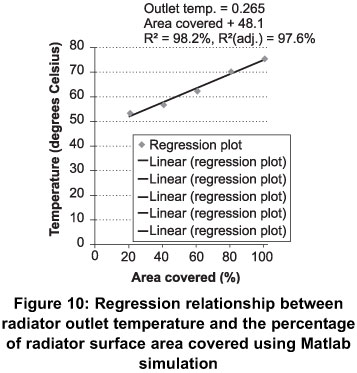
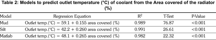
Table 2 shows the regression models used to predict the outlet temperatures of radiator coolant from the percentage of area covered of the radiator. The three models were developed using silt and mud to cover the radiator. The Matlab model was a simulated model to evaluate the validity of the silt and mud models. All the three models predicted well and were statistically significant at a 1% probability level. The coefficient of determination (R2) of the three models ranged from 0.98 to 0.99. At least 99% of the variation in the outlet coolant temperatures was explained by the percentage of the area covered of the radiator. For the silt model, for every 10% increase or decrease of the area covered of the radiator resulted in an average increase or decrease of about 1.7 degree Celsius of the outlet temperature of the radiator coolant. In the case of the mud model, a 10% increase or decrease of the area covered of the radiator resulted in about 2.1 degrees Celsius of the outlet temperature of the radiator coolant (Table 2). In the Matlab model, a change in 10% of the area covered of the radiator resulted in a change of about 2 degrees Celsius of the outlet temperature of the radiator coolant.
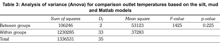
Analysis of variance (Anova) was conducted to find out if there were statistically significant differences among the three models (Table 3). As shown in Table 3, there were no statistically significant differences among the three models. This indicates that the Matlab model was consistent with the mud and silt models. It can also be said when the same amount of mud or silt covers the same area of a radiator the same temperature rise of the radiator coolant will result.
5. Conclusions
Experiments were successfully conducted on the radiator of a four cylinder diesel at base load. Two different soil types, namely silt and mud, were used as covering material to cover the heat transfer area of the radiator to determine the heat transfer process during the running of the engine. It was observed that the inlet temperature of the coolant in the radiator increased as the percentage area of the radiator covered increased. It was also observed that the outlet temperature of the coolant from the radiator increased monotonically with increases in the percentage area of the radiator covered. In both cases, at 80% coverage of the heat transfer area of the radiator the engine vibrated excessively and the idling was not stable. The engine stopped running after a short while. At 100% coverage the engine stopped running immediately after starting. This phenomenon was expected because as the effective transfer area of the radiator is reduced, less heat is taken out and thereby affecting the temperature of the coolant and hence the performance of the engine.
A mathematical model was developed to predict the heat transfer phenomenon. The model developed predicted the heat transfer so well. It was observed that the inlet temperature of the coolant in the radiator increased as the percentage area of the radiator covered increased. The outlet temperature of the coolant from the radiator also increased as the percentage of the area of the radiator increased. It was also observed that the heat transfer model developed agreed with the experimental results.
The analysis of variance results pointed to the fact that the results obtained for silt, mud and the mathematical model were not significantly different at 95% confidence interval. This point to the fact that, irrespective of the covering material, the effect of temperature rises will effectively be the same.
References
Kem, J. and Ambros. P (1997). Concepts for a controlled Optimized Vehicle Engine Cooling System. Society of Automotive Engineers Publication, 971816, 357-362. [ Links ]
Oliet, C., Oliva, A., Castro, J., Perez-Segarra, C.D. (2007). Parametric studies on automotive radiators, Applied Thermal Engineering, 2033-2043. [ Links ]
Pulkrabek, W.W. (1997). Engineering Fundamentals of the Internal Combustion Engine, pages 270-280. [ Links ]
Mudd, S.C. (1972). Technology for Motor Vehicle Mechanics, Euston Road London, Oxford Press. [ Links ]
Kiatsiriroat, T. (2004). The application of automobile radiator in waste heat recovery process, Final Report, Energy Planning and Policy Office, Thailand. [ Links ]
Nuntaphan, A. and Kiatsiriroat,T. (2004). Performance of thermosyphon heat exchanger modified from automobile radiator, in: The 18th Conference of Mechanical Engineering Network of Thailand, Kon Kaen, Thailand. [ Links ]
Received 4 May 2012
Revised 30 October 2013

