


Services on Demand
Article
 English (pdf)
 Article in xml format
 Article references
Indicators

Related links
-
 Cited by Google
 -
 Similars in Google
Share

 Permalink
Journal of the South African Institution of Civil Engineering
On-line version ISSN 2309-8775
Print version ISSN 1021-2019
J. S. Afr. Inst. Civ. Eng. vol.64 n.1 Midrand Mar. 2022
http://dx.doi.org/10.17159/2309-8775/2022/v64no1a5
TECHNICAL PAPER
Evaluation of the seismic response of a reinforced concrete footing with stub column to increasing peak ground acceleration using pseudo-dynamic experimentation
S M Hossell; C P Roth
ABSTRACT
The pseudo-dynamic experimentation technique was investigated to evaluate the damage occurring in a reinforced concrete footing with stub column due to the overall response of a linear elastic two-storey, two-bay moment-resisting steel frame structure that is subjected to an earthquake excitation with increasing peak ground acceleration. The implicit Newmark's method with static condensation was utilised in the present study to solve the governing equation of motion of the multi-degree-of-freedom system. Five pseudo-dynamic experiments were performed by scaling the El Centro ground motion record, which occurred in California on 18 May 1940, to produce peak ground accelerations that ranged between 0.34 g and 2 g. All the laboratory experiments were undertaken under a constant axial load for the duration of the applied earthquake excitation, and utilised Rayleigh damping to model the energy loss within the overall structure. The pseudo-dynamic method provides a reliable method to relate damage suffered by the stub column due to the overall structure's response to the applied earthquake excitation. The method enables the structural capacity and failure mechanisms of the reinforced concrete stub column to be observed in relation to the seismic demand. The hysteretic response of the stub columns and energy dissipation characteristics were determined, and it was shown that the yield strength of the longitudinal reinforcement within the stub column has a significant impact on the maximum shear capacity and damage incurred by the stub column. The damage is more pronounced with an increase in the number of cycles of vibration, particularly at displacements that exceed the yield strength of the reinforcement. An increase in the hysteretic energy dissipated by the reinforced concrete stub column results in a concomitant increase in the observed damage to the stub column in the form of concrete cracking, reinforcement yielding and spalling of the concrete.
Keywords: pseudo-dynamic experimentation, reinforced concrete stub column, seismic performance evaluation, hysteretic curves, Newmark's implicit numerical method, El Centro earthquake
INTRODUCTION
The pseudo-dynamic testing technique is a computer-controlled experimental method whereby the dynamic behaviour of the structure is mathematically calculated on a computer and the resultant displacement is statically applied to the physical test specimen of the structure at a common degree of freedom between the numerical model and the physical model using servo-controlled actuators in an online procedure (Mosalam et al 1997). The pseudo-dynamic testing technique uses the same equipment as conventional quasi-static tests; however, the analysis is controlled by a closed-loop system comprising computer software that is integrated and runs in tandem with the quasi-static experiment. The method utilises well-established step-by-step time integration methods and utilises the same numerical approach generally undertaken in nonlinear structural dynamics; however, the structural restoring force is based on experimental feedback from load cells as opposed to an idealised material model (Wang et al 2006). The force obtained from the load cell, due to the calculated displacement from the numerical model, is fed back into the computational model and used in successive iterations to determine the new displacement. Historically, reinforced concrete stub columns have been experimentally tested using both quasi-static monotonic load tests and cyclic load tests to determine the performance of the structure; however, the experiments are not able to relate the progressive damage incurred to the reinforced concrete stub column for the duration of a realistic earthquake excitation (Mosalam et al 1998). Therefore, the pseudo-dynamic experimental method enables the cumulative damage to be related to earthquake intensity (Mosalam et al 1998; Takanashi et al 1975).
Background
The performance of structures during an earthquake of given intensity dictates the extent of damage and loss of life that become associated with the earthquake event. Quantifying the level of damage within a structure that has occurred during an earthquake is traditionally undertaken post-earthquake using statistical methods. However, this method is not suitable in areas with moderate seismicity, as insufficient data is available to calibrate structural damage to an earthquake intensity parameter. Southern Africa is characterised as a region of moderate seismicity, and due to the limited network of accelerometers within South Africa, a detailed statistical analysis of the level of damage that could occur within structures during future earthquakes has been prevented (Brandt 2011).
Quantifying the level of damage incurred by a structure due to increasing earthquake intensity is a complex task. Typically, structural components are evaluated using quasi-static methods to determine the response due to increasing load and to determine the ultimate load-carrying capacity of the member. However, the slow rate of the load applied onto the structure results in the inertia of the structure not being considered, resulting in the response of the structure being independent of the applied earthquake loading. To relate earthquake intensity to damage, shake-table testing or pseudo-dynamic testing provides a more accurate damage correlation with earthquake intensity. Shake-table tests provide the most realistic means to evaluate damage at various intensities, as they account for the inertial effects and the time and frequency content of the ground motion. However, shake tables are very expensive and difficult to evaluate large-scale multi-storey structures for a range of earthquake intensities. Advancements in computer software, the increase in the resolution of the control systems and data acquisition systems, and the ability of pseudo-dynamic tests to incorporate the dynamic characteristics of a structure have made the method a feasible alternative to shake-table tests to evaluate the performance of a structure at various earthquake intensities. This could aid in the development of fragility curves and in determining the risk of damage at various earthquake intensities.
Objective of the study
The primary objective of the study was to demonstrate the application of the pseudo-dynamic experimental method to relate the resultant structural damage, hysteretic response and energy dissipation capacity of a reinforced concrete footing and stub column under a constant axial load that forms part of a two-bay two-storey moment-resisting steel frame structure, to increasing peak ground acceleration (PGA). Figure 1 shows the hypothetical structure that was considered in this research, and the position of the reinforced concrete footing and stub column under investigation. The feasibility of using the pseudo-dynamic method with Newmark's implicit time-stepping numerical method with static condensation was investigated by analysing a single member of a structure that forms part of an overall structural system that remains linearly elastic for the duration of the experiment. The study also investigated the maximum peak ground acceleration that the member could encounter before failure, and therefore the experiments were undertaken at increasing amplitudes.
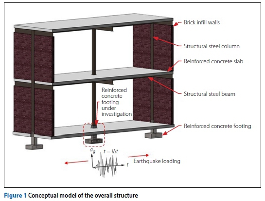
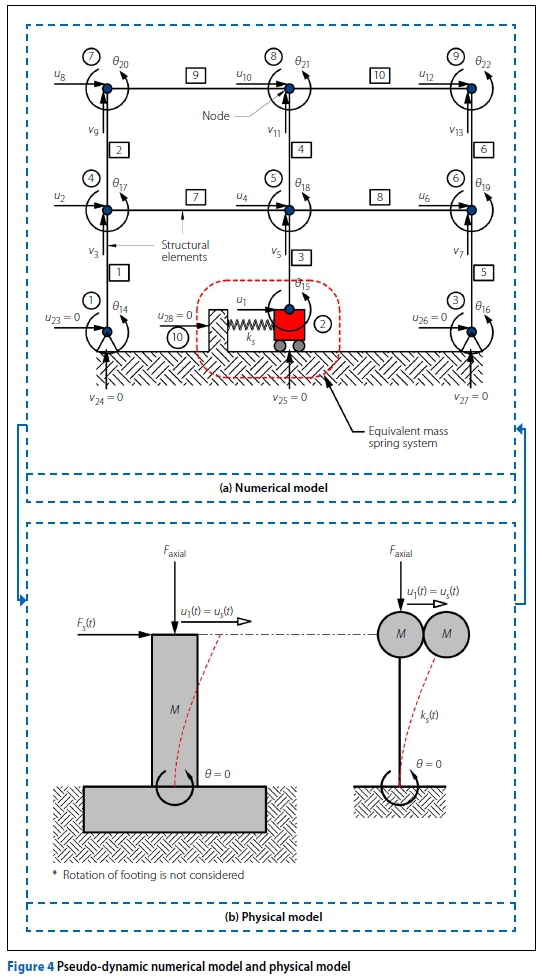
The footing shown in Figure 1 was assumed to be fixed against rotation, and the steel structure above was assumed to be connected to the footing and stub column by a pin joint. The effect is that the footing and stub column assembly provides an infinitely stiff vertical support to the steel structure, and a nonlinear spring form of horizontal support.
Limitations of the study
The susceptibility of damage to a reinforced concrete footing and stub column during an earthquake is dependent on several factors that relate to the type of structure placed on the footing and stub column, the ground conditions, the boundary conditions, and the type of earthquake excitation to which the structure is subjected. The size of the reinforced concrete footing and stub column that could be evaluated and the magnitude of the applied axial load were limited by the capacity of the press frame that was available in the laboratory. The study focused on evaluating the pseudo-dynamic testing method using only the Newmark implicit numerical time integration method, and only the El Centro ground motion record was used in the analysis, with the peak ground acceleration of the earthquake excitation being the only variable. The reinforced concrete footing and stub column was subjected to a constant axial load for the duration of the earthquake record, and therefore the response of the stub column due to a varying axial load was not investigated. Only a reinforced concrete footing and stub column of a single design that satisfied the minimum reinforcement requirements contained in SANS 10100-1:2000 (SANS 2000) was considered in this research. The two-dimensional frame structure, which was placed on the footing and stub column, remained linearly elastic for the duration of the earthquake record, and energy loss within the overall frame structure was treated using Rayleigh damping with a damping ratio of 5%, as is typically used in design codes (SANS 2017; Chopra 2012). The capacity of structural members and their connections within the overall frame structure were not considered during the analysis, and therefore the formation of plastic hinges and the resulting loss of stiffness within the overall structure were not considered when determining the response of the reinforced concrete footing and stub column to the applied earthquake load.
RELEVANT LITERATURE
Pseudo-dynamic testing originated approximately forty years ago as an alternative to shake-table testing, with Takanashi et al (1975) seen as one of the pioneers of the testing method (Kurt 2010). Pseudo-dynamic testing is especially efficient when having to test structures that are too heavy or too large to be practically tested on available shake tables (Thewalt & Mahin 1987). Pioneering work in pseudo-dynamic testing was done by Hakuno in 1969 (as cited by Takanashi et al 1975) where he tested cantilever beams using an online system that comprised an analogue computer and an electromagnetic actuator. However, the results produced by the test were rather poor due to the limitations of the available hardware. Following on the work that was done on cantilever beams, Takanashi et al (1975) did substantial work in establishing the pseudo-dynamic technique by replacing the analogue computer with a more accurate digital computer. Modifications done by Takanashi et al (1975) enabled the procedure to not have to operate in real time, thus producing a method that could be subjected to slow loading and pausing. The first pseudo-dynamic tests were restricted to planar test specimens that were subjected to a single horizontal component of base excitation (Takanashi et al 1975; Shing & Mahin 1984; Takanashi & Nakashima 1987).
However, the method can be easily adapted to analyse the three-dimensional response of structures with several components of base excitation (Thewalt & Mahin 1987). Multi-degree-of-freedom testing was done by Chang (2009) whereby he subjected a one-storey frame to bidirectional loading. Mosalam et al (1998) investigated the response of masonry infill frames using the pseudo-dynamic method and indicated that the pseudo-dynamic method provides an acceptable approximation of the dynamic response of a structure that is subjected to earthquake excitation.
FORMULATION OF THE PSEUDO-DYNAMIC METHOD
The pseudo-dynamic method is formulated from the time-discretised equation of motion for each time step "i" as shown by Equation 1. During pseudo-dynamic experimentation, Equation 1 is solved using numerical methods in a stepwise procedure with the restoring force Fs= [Ks(t)]{u(t)}, measured directly from the test specimen using a load cell (Kurt 2010). Therefore, the value of [Ks(t)] is calculated from the measured value Fsforce obtained from the load cell due to the displacement {u(t)} applied by the linear hydraulic actuator to the test specimen and calculated in the numerical model of the overall frame structure. The solution of the second order differential equation can be solved using either implicit or explicit numerical methods to solve the displacements at each time step.
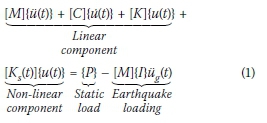
Where:
[M]: Lumped mass matrix of the frame structure including the mass of the reinforced concrete footing and stub column
[C]: Rayleigh damping matrix for the elastic part of the frame structure
[K]: Linear elastic stiffness matrix of the frames structure
{ü(t)}, {μ(t)}, Acceleration, velocity and {μ(t)}: displacement vector respectively
[Ks(t)]: Lateral non-linear spring stiffness matrix of the reinforced concrete footing and stub column
{I}: Influence vector that accounts for the horizontal direction of the earthquake loading
üg(t): Ground acceleration.
The preference in the past has traditionally been towards explicit numerical methods because of the disinclination to numerical iteration at each time step. However, advancements in computational power and the increase in the resolution of computers have made using implicit numerical methods more favourable due to the superior stability properties they provide (Mosalam et al 1997). Newmark's implicit method has been widely adopted in finite element analysis software to solve nonlinear problems as it can be unconditionally stable for any time increment (Chopra 2012). Therefore, the selection of the time increment only influences the accuracy of the solution and not the stability.
EXPERIMENTAL PROCEDURE
Five pseudo-dynamic experiments were conducted on the reinforced concrete footings and stub columns at increasing peak ground accelerations (PGA) obtained by amplifying the El Centro earthquake to correlate damage with increasing peak ground acceleration. The PGA considered during this study comprised 0.34 g, 0.68 g, 0.78 g, 1 g and 2 g. The testing procedure required the programming of the implicit Newmark numerical algorithm into the HBM Catman software (HBM 2016) using the Visual Basic scripting language, and the software was integrated with the hardware upon completion of the scripting. The displacement transducers and load cells were calibrated before testing, and the integration between the hardware and the software was tested to ensure that the servo-controller accurately interpreted the calculated displacement.
Each of the experiments started by initialising the actuators and ensuring the horizontal load on the stub column was equal to zero. The axial load was then applied to the stub column, and once the axial load reached 300 kN, the horizontal actuator was initialised on the servo-controller. The initial calculation within the software ensured that all the instruments were zeroed, and the static analysis was first performed to determine the initial load state of the structure before commencing the pseudo-dynamic analysis. Time-stepping and iteration commenced upon completion of the initial calculations whereby the amplified El Centro earthquake record was applied to the overall structure.
The initial horizontal stiffness of the reinforced concrete footing and stub column was required before the pseudo-dynamic analysis could commence. The initial stiffness of the footing and stub column also enabled the elastic natural period of vibration of the structure to be determined, which was used to calculate the damping matrix for the overall frame structure.
Earthquake loading on the structure
The El Centro earthquake, S00E of the event at Imperial Valley, California, on 18 May 1940, was selected as the input ground motion and is shown in Figure 2. The El Centro ground motion record represents a strong ground shaking and is commonly used for shake-table tests and pseudo-dynamic experiments (Mosalam et al 1998). For each of the pseudo-dynamic tests undertaken in this study, the peak ground acceleration was increased by scaling the amplitude of the El Centro earthquake.
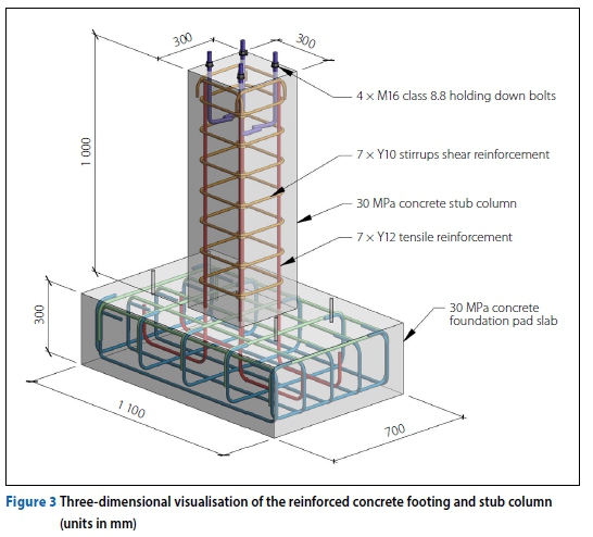
Test specimen
The reinforced concrete footing and stub column that were used in the research are shown in Figure 3. The reinforced concrete stub column only required minimal reinforcement to resist the applied gravity and wind loads that were used to design the structure. The characteristic design yield stress of 450 MPa and a Young's Modulus of 200 GPa were used for the design of the reinforcement, and a characteristic com-pressive strength of 30 MPa was used for the concrete.
Application of the pseudo-dynamic method using Newmark's implicit method
Figure 4 shows the discretised numerical model used in the pseudo-dynamic analysis procedure in this research. The frame structure was discretised into 28 degrees of freedom with the boundary conditions comprising two pin supports at the external columns, and with the internal stub column's lateral degree of freedom idealised as a single degree of freedom consisting of a constant lumped mass that was supported laterally by a massless nonlinear spring of stiffness ks(t). The degree of freedom {us= u1 coupled the calculation cycle with the laboratory test specimen. The horizontal displacement {u1} was taken at the top of the stub column, as shown in Figure 4, where the steel column of the frame structure connects to the footing and stub column using a base plate and holding-down bolts.
Loading cycle - physical test setup
A conceptual model of the experimental test setup is shown in Figure 5. The test setup comprised two actuators and two load cells, with the vertical actuator being used to simulate the constant axial load applied by the structure on the stub column, which corresponds to the degree of freedom shown in Figure 4. The horizontal actuator was used to simulate the varying horizontal shear load on the stub column due to the applied earthquake excitation that was calculated from the computational model of the frame structure.
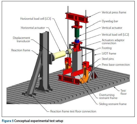
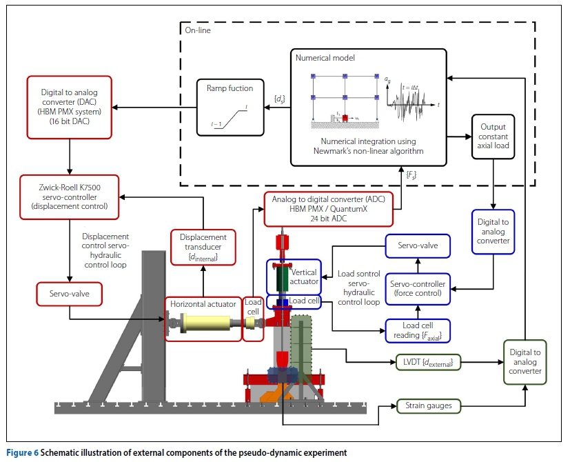
The displacement uscalculated in the computer model was applied directly to the stub column using the horizontal actuator with the corresponding force Fsmeasured using the horizontal load cell [LC1]. The horizontal force was subsequently fed back into the numerical model at which time the numerical model computation continued. Figure 6 shows the hardware and software that were used to integrate the calculation cycle with the loading cycle on the test specimen. Two control loops were used in the experimental tests, with the first control loop being used under force control to maintain the vertical axial load on the reinforced concrete stub column. The second control loop was used under displacement control to apply the horizontal displacement calculated in the numerical model onto the reinforced concrete stub column at each iteration within each time step. A linear ramp function was used to apply the load incrementally and delay the rate of lateral load applied onto the stub column. The objective of the ramp function was to mitigate dynamic effects during the analysis due to large changes in calculated displacements between iterations.
Figure 6 also shows a third path that comprised additional instruments attached to the experimental test setup. Strain gauges were attached to two of the four longitudinal reinforcing bars. The strain gauges were applied at the base of the column where the maximum moment was expected. Four additional linear displacement transducers were placed at equal increments over the length of the column with the aim to validate the results with the internal displacement transducer in the horizontal actuator.
Calculation cycle numerical model
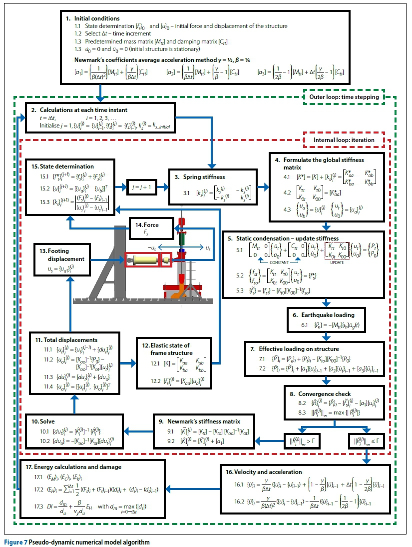
The nonlinear Newmark's implicit method, using the average acceleration method, was used to perform the pseudo-dynamic experiments, and Figure 7 shows the pseudo-dynamic algorithm used to run the analysis. The algorithm was adapted to incorporate static condensation to eliminate the rotational free degrees of freedom with zero mass within the overall frame structure. The unknown displacements and forces within the structure using the initial state of the structure are solved at each time step:
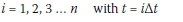
With n being the total number of time steps in the earthquake record, and t being the time in seconds at any point within the analysis.
The average acceleration method produces an unconditionally stable solution, and therefore the selection of the time step only influenced the accuracy of the solution and not the stability of the solution. For each time step "i" within the earthquake record, iteration "j" was required due to the implicit relationship between the restoring force matrix (f*s)iand the unknown displacement of the structure at (u)ias shown in Step 15 in Figure 7. Therefore, the stiffness of the footing and stub column must be assumed before the calculation at each time step can be initialised. The selection of the initial lateral stiffness of the footing and stub column had to be considered carefully, because assuming a stiffness that was lower than the true elastic stiffness of the footing and stub column would produce premature damage to the stub column at the start of each time step (Pegan & Pinto 2000). Also, selecting a stiffness that is lower than the elastic stiffness of the footing and stub column can also result in instability problems in the convergence of the solution.
Reinforced concrete is a highly nonlinear material, and with the application of the applied loading at the beginning of each time step, an initial out-of-balance residual force vector was produced. As a result, the structure was no longer in force or energy equilibrium. In general, the displacement applied to the structure results in a restoring force that differs from that of the restoring force calculated using the initially assumed stiffness of the structure. Because of this, the stiffness of the footing and stub column (ks) between the previous time step and the current time step needed to be updated at each iteration until convergence was reached, which was achieved once the infinity norm was reduced to below the prescribed stop criteria (r) shown in Figure 7. This needs to be done to ensure force and energy equilibrium at each time step. The HBM data acquisition system has a 16-bit digital-to-analogue converter (DAC) and produced an output resolution of 0.003 mm for the horizontal actuator with a stroke length of 200 mm (shown previously in Figure 5) that was used to apply the load onto the specimen. Therefore, the stop criteria in the research, indicated by (r) in Figure 7 was selected to be less than the resolution of the data acquisition system. Once the solution converged, and equilibrium within the structure was achieved, the next time step "i" could commence.
RESULTS OF THE PSEUDO-DYNAMIC EXPERIMENTS
The hysteretic behaviour of each of the reinforced concrete stub columns is provided and the observed damage is discussed in terms of cracking, concrete spalling, reinforcement buckling, and fracturing for each of the pseudo-dynamic experiments.
Hysteretic relations and crack patterns
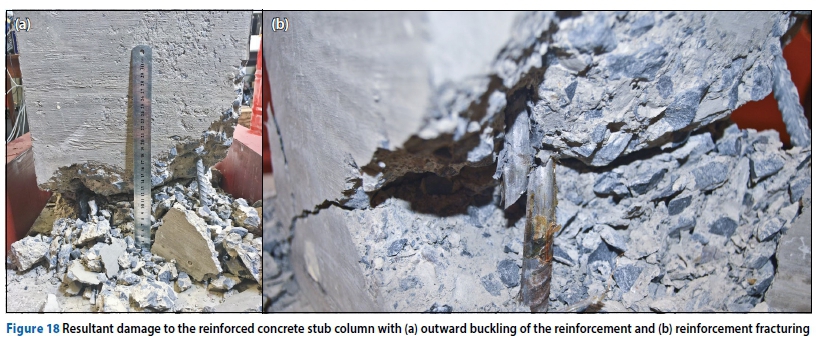
The hysteretic results and force-versus-time results for each of the experiments are shown in Figures 8 to 17, with the peak ground accelerations (PGA) ranging from 0.34 g to 2 g. Only minimal cracking had occurred at a PGA of 0.34 g, with complete failure having occurred at a PGA of 2 g. Figures 18 and 19 show the damage to the reinforced concrete stub columns during the 0.78 g PGA test. The column continued to carry the axial load until the cross-sectional area had reduced substantially, resulting in the axial capacity of the stub columns being exceeded. The structure subjected to the 0.78 g PGA test collapsed due to the formation of a plastic hinge and the loss of axial load carrying capacity. Figure 18 shows the buckled and fractured reinforcement due to excessive lateral deformation of the stub column during the 0.78 g PGA test, and Figure 19 shows the formation of the plastic hinge at collapse of the stub column.
The results produced during the pseudo-dynamic experimentation were validated by replacing the physical test setup with bilinear hysteretic shear models to observe the expected damage over a range of PGAs. During the experiments, convergence was achieved for each time step for the duration of the applied earthquake record, and the damage observed to the footing during the experiment corresponded with hysteretic curves and the absorbed energy due to the plastic deformation and buckling of the reinforcement, concrete spalling and concrete crushing. The calibrated strain gauges attached to the reinforcement indicated the onset of reinforcement yielding that corresponded to the flattening of the hysteretic curve. However, the strain gauges failed at larger deformations and were therefore not able to compare the calculated energy absorbed from the hysteretic curve with the results from the strain gauges. The displacements obtained from the external LVDTs were used to ensure that the displacement applied by the servo controller was correct at each time step.
Table 1 summarises the results obtained during the pseudo-dynamic experiments for the following critical points: the minimum cracking force (Fc) and cracking deformation («c), the minimum reinforcement yielding force (Fy) and deformation (Uy), and the maximum achieved force (Fm) and deformation (um). The following observations were made during the pseudo-dynamic experiments:
■ With increasing deformation, the shear load-carrying capacity tends to a constant value with a subsequent reduction in the lateral stiffness of the footing and stub column, and therefore there is a maximum shear load that the structure is capable of transferring between the ground and the structure as deformation increases.
■ The lateral capacity of the reinforced concrete stub column and subsequent damage are predominately controlled by the yield strength and ductility of the reinforcement.
■ An increase in the applied lateral deformation applied to the stub column results in cracking and yielding of the reinforcement, which in turn result in a reduction in the lateral stiffness of the stub column.
■ The ductility of the reinforced concrete stub column is controlled by the tensile reinforcement and the shear reinforcement.
■ Cracks occurred near the base of the column where the maximum moment was expected; however, the cracks did not always open at the interface between the base of the column and the top of the stub column.
■ The number of cycles of vibration increases the damage to the reinforced concrete stub column, particularly when the load reverses after the reinforcement has yielded.
■ Spalling of concrete occurs due to the buckling of reinforcement during load reversal from tensile loading to compression loading on either face of the concrete column in the direction of loading, thus resulting in a reduction in shear capacity with each cycle as indicated in Figure 12. This occurs due to the incompatibility between the brittle concrete material and the ductile reinforcement. Upon load reversal, the permanently elongated reinforcement is first mobilised in compression before the crack that has formed in the concrete can close and mobilise in compression. To overcome this incompatibility, the reinforcement buckles, resulting in the spalling of the concrete. The spalling of the concrete concomitantly results in a reduction in the gross cross-sectional area of the column, which in turn results in a decrease in the axial and shear capacity of the stub column.
■ At high peak ground accelerations, the failure tends to that obtained during quasistatic tests with little to no concrete spalling and the failure governed by fracturing of the reinforcement and crushing of the concrete as shown in Figures 14 and 16. This results in little to no reduction in shear capacity prior to failure.
■ The unloading stiffness from the backbone curve (the curve produced during quasistatic experiments) of the stub column is greater than the reloading stiffness into the backbone curve, which indicates that the structure is absorbing energy and incurring damage.
■ Before the reinforcement yields, the response under cyclic loading remains predominantly perfectly plastic without any significant permanent deformation.
■ The loss of moment capacity due to the formation of a plastic hinge is governed by the repeated cycling of the stub column at a displacement less than the quasistatic loading failure displacement and greater than the yielding displacement of the reinforcement.
■ Increasing the amplitude of the El Centro ground motion record showed that there is a maximum PGA that can be sustained by the stub column before failure occurs. For example, the pseudo-dynamic test that was undertaken by amplifying the El Centro ground motion record to a PGA of 2 g only managed to achieve a maximum PGA of 1.21 g before failure occurred.
Energy-related results
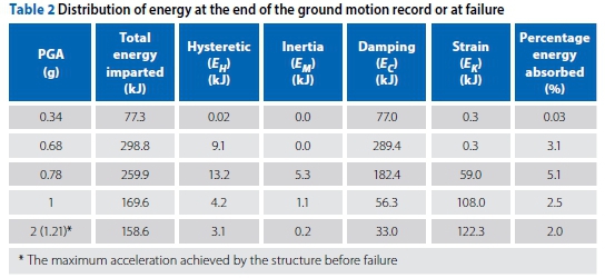
The amount of energy imparted to the structure due to the earthquake is distributed between the kinetic energy (EM), damping energy (Ec), strain energy (EK) and hysteretic energy (EH). This section shows the distribution of energy within the structure for each of the pseudo-dynamic tests. Figure 20 shows the time history of the total energy imparted to the structure for the duration of each of the scaled earthquake ground motion records during the pseudo-dynamic experiments and is either shown for the entire duration of the earthquake record or until structural failure of the reinforced concrete stub column. The experiments conducted at 0.34 g and 0.68 g ran for the full duration of the earthquake record, whereas the 0.78 g, 1 g and 2 g experiments all failed before completion of the earthquake record. The maximum energy imparted to the structure occurred during the experiment with a maximum peak ground acceleration of 0.68 g, and the tests undertaken at larger peak ground accelerations showed a reduction in the total energy imparted to the structure before failure of the stub column occurred.
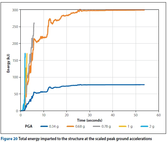
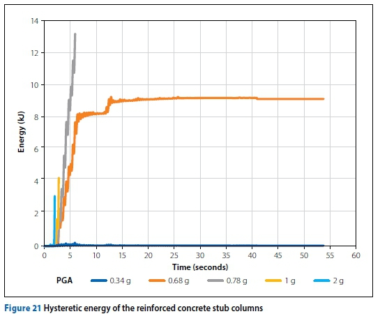
Figure 21 shows the total hysteretic energy absorbed as time progressed with the application of the scaled El Centro ground motion record for each of the pseudo-dynamic tests. Table 2 shows the distribution of energy within the structure for each of the amplified ground motion records, which is either recorded at the end of the earthquake record or at failure of the stub column. Table 2 also provides the amount of energy absorbed by the stub column as a percentage of the total energy imparted to the frame structure. The stub columns that showed more substantial observed damage during the experiments absorbed the largest quantity of energy. The 0.78 g ground motion record resulted in the most observed damage and absorbed the greatest quantity of energy as is seen in Figure 21. Even though the 1 g and 2 g ground motion records resulted in the failing of the structure, the amount of energy absorbed by the stub column is less than that absorbed by the 0.68 g and 0.78 g earthquake. Therefore, the hysteretic energy absorbed by the stub column gives a good indication of damage incurred by the stub column under repeated cyclic loading, but does not indicate structural failure at large deformations with few or no cycles of vibration.
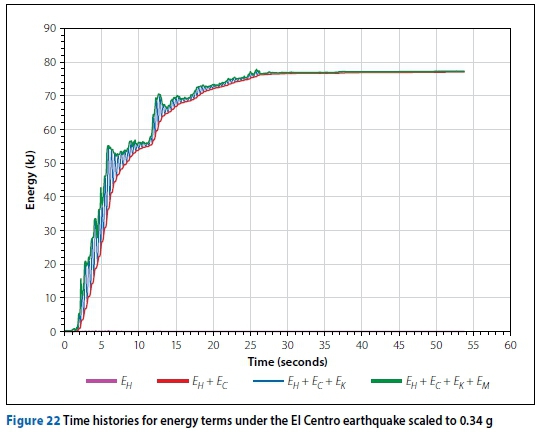
Figures 22 to 26 show the energy components for the frame structure for the entire duration of the ground motion record that were scaled to produce a 0.34 g and 0.68 g peak ground acceleration. The structure subjected to the 0.34 g peak ground acceleration resulted in damping absorbing all the energy imparted to the structure. The 0.68 g peak ground acceleration resulted in the stub column absorbing hysteretic energy and therefore indicates a correlation between the number of cycles of vibration and the resultant damage in terms of observed concrete spalling, yielding and buckling of the reinforcement. The ductility provided by the reinforcement has a significant influence on the quantity of energy that can be absorbed by the stub column before the failure displacement is exceeded.
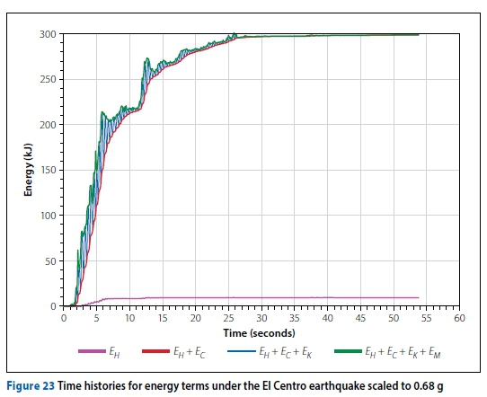
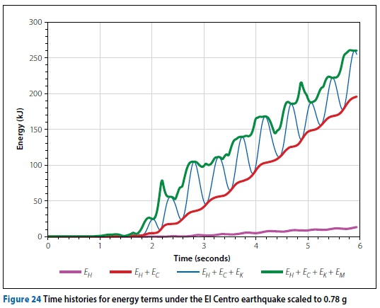
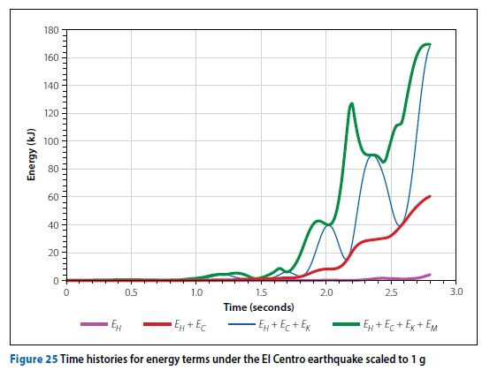
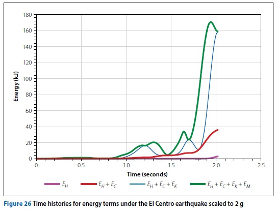
The test at 0.34 g did not absorb a large amount of energy as the stub column did not undergo significant lateral deformation and the reinforcement did not yield. For the tests at peak ground accelerations of 0.68 g and 0.78 g, the stub columns underwent a larger number of cycles of vibration in the plastic region of the reinforcement, which consequently resulted in more damage to the stub column due to the spalling of the concrete cover. The spalling of the concrete cover occurred predominately due to the buckling of the permanently elongated reinforcement upon load reversal from tension to compression, and to a lesser extent due to compression capacity of the concrete being exceeded. The tests carried out at 1 g and 2 g had fewer or no cycles of vibration before the reinforcement fractured and visually did not experience the same amount of damage in terms of concrete crushing and spalling of the concrete cover than what was observed from the tests conducted at lower peak ground accelerations.
It is evident that most of the energy absorbed in the structure is due to Rayleigh damping, with only a small percentage of the overall energy absorbed by the reinforced concrete stub column. The hysteretic energy correlates well with the cumulative damage to the reinforced concrete stub column and the observed damage experienced by the specimens during the pseudo-dynamic experiments.
CONCLUSIONS
The pseudo-dynamic experimental method using Newmark's implicit time-stepping method was presented. It is concluded that the method provides a viable approach to correlate damage to a physical test model of a reinforced concrete footing and stub column, which forms part of an overall structure, with increasing earthquake intensity. The hysteretic curves produced from the pseudo-dynamic experiment were validated through the combination of strain gauges attached to the reinforcement, LVDTS and running the pseudo-dynamic algorithm using bilinear hysteretic numerical shear model to ensure that convergence to a solution was achieved. The damage observed during the pseudo-dynamic experiments also corresponded with the hysteretic results and strain energy absorbed during the applied earthquake. The use of the implicit Newmark's method provided a stable and accurate algorithm to quantify the damage incurred to the reinforced concrete stub column due to the overall response of the structure that had been subjected to an applied seismic load. Convergence to a solution was achieved at each time step for the duration of the applied earthquake, thus ensuring energy and force equilibrium, further validating the method. The initial stiffness that is used within the implicit Newmark's algorithm must be greater than the maximum achievable stiffness of the specimen being tested to ensure the stability of the analysis and prevent the formation of premature damage.
By using the pseudo-dynamic method, the hysteretic response of the footing and stub columns could be related to earthquake intensity, and observations could be made on the extent of damage incurred by the stub column due to the applied earthquake loading. The reinforced concrete stub column only dissipates a small percentage of the overall energy imparted to the structure in the form of hysteretic energy, with the remainder of the energy being dissipated due to damping within the frame structure, which consists of a number of structural elements. The extent of damage to the reinforced concrete stub column is governed predominately by the yield strength of the reinforcement, with the rate of damage and hysteretic energy absorption increasing substantially once the reinforcement has yielded. The research showed that lower PGAs tend to result in the absorbed hysteretic energy and cyclic behaviour of the stub column governing the failure of the stub column, whereas at large PGAs the fracturing of the reinforcement tends to dominate the failure of the structure. Therefore, using pseudo-dynamic experimentation on a number of structural members can be used to determine the risk of damage and failure of a structural member with increasing earthquake intensity.
RECOMMENDATIONS FOR FURTHER WORK
Cognisance should be given to the fact that the analysis undertaken during this research only considered a single reinforced concrete stub column design that was analysed using a single earthquake ground motion record. Therefore, recommendation for future work would include the following:
■ Analysing the structure by varying the longitudinal and shear reinforcement to determine the influence it has on the damage incurred by the stub column.
■ Testing reinforced concrete stub columns with closed seismic stirrups and comparing the capacity with the results produced using traditional stirrups.
■ Performing pseudo-dynamic experiments that account for both a varying shear and axial loading as could be experienced by foundations placed on the exterior of a building.
■ Determining the influence that compacted soil around the stub column has on the response of the reinforced concrete stub column and the resultant damage, therefore incorporating soil-structure interaction into the analysis.
■ Performing pseudo-dynamic experiments that enable the analysis of the reinforced concrete stub column under biaxial bending and shear.
■ Performing pseudo-dynamic tests on reinforced concrete stub columns by accounting for non-linear behaviour within the overall structure and determining what influence the softening of the overall structure will have on the performance of the stub column.
ACKNOWLEDGEMENTS
This research has been funded by MMI Holdings Limited and the University of Pretoria's Natural Hazard Centre, NRF THRIP Funding TP 14072278140 and NRF funding Grant: 103724 and Grant: TP14072278140. These sponsors are gratefully acknowledged for their contributions. Any opinions, conclusions and recommendations are those of the authors and do not necessarily reflect those of the sponsors.
REFERENCES
Brandt, M 2011. Seismic hazard in South Africa. Report No 2011-0061. Pretoria: Council for Geoscience. [ Links ]
Chang, S 2009. Bidirectional pseudodynamic testing. Journal of Engineering Mechanics, 135(11): 1227-1236. [ Links ]
Chopra, A K 2012. Dynamics of structures. Theory and Applications to Earthquake Engineering. Upper Saddle River, NJ: Prentice Hall. [ Links ]
HBM (Hottinger Baldwin & Messtechnik GmbH) 2016. Catman Data Acquisition Software - CatmanAP, Version V4.2.2.14. Darmstadt, Germany: HBM. [ Links ]
Kurt, E G 2010. Investigation of strengthening techniques using pseudo-dynamic testing. Ankara, Turkey: Middle East Technical University. [ Links ]
Mosalam, K M, White, R N & Ayala, G 1998. Response of infilled frames using pseudo-dynamic experimentation. Earthquake Engineering and Structural Dynamics, 27: 589-608. [ Links ]
Mosalam, K M, White, R N & Gergely, P 1997. Seismic evaluation of frames with infill walls using pseudo-dynamic experiments. Technical Report NCEER-97-0020. Ithaca, NY: Cornell University. [ Links ]
Pegan, P & Pinto, A V 2000. Pseudo-dynamic testing with substructuring at the ELSA Laboratory. Earthquake Engineering and Structural Dynamics, 29: 905-925. [ Links ]
SANS (South African National Standard) 2000. SANS 10100-1. The Structural Use of Concrete. Part 1. Design. Pretoria: SABS Standards Division. [ Links ]
SANS (South African National Standard) 2017. SANS 10160-4. Basis of Structural Design and Actions for Buildings and Industrial Structures. Part 4. Seismic Actions and General Requirements for Buildings. Pretoria: SABS Standards Division. [ Links ]
Shing, P B & Mahin, S A 1984. Pseudodynamic test method for seismic performance evaluation: Theory and Implementation. Report No UCB/EERC-84/01. University of California, Berkeley: Earthquake Engineering Research Centre. [ Links ]
Takanashi, K, Udagawa, K, Seki, M, Okada, T & Tanaka, H 1975. Non-linear earthquake response analysis of structures by a computer-actuator on-line system. University of California, Berkeley: Earthquake Engineering Research Centre. [ Links ]
Takanashi, K & Nakashima, M 1987. Japanese activities on on-line testing. Journal of Engineering Mechanics, 113(7): 1014-1032. [ Links ]
Thewalt, C R & Mahin, S A 1987. Hybrid solution techniques for generalised pseudodynamic testing. Report No UCB/EERC-87/09. University of California, Berkeley: Earthquake Engineering Research Centre. [ Links ]
Wang, T, Nakashima, M & Pan, P 2006. On-line hybrid test combining with general-purpose finite element software. Earthquake Engineering and Structural Dynamics, 35: 1471-1488. [ Links ]
 Correspondence:
Shane Hossell
Department of Civil Engineering, University of Pretoria
Pretoria 0002, South Africa
T: +27 82 806 1136; E: shanehossell@gmail.com
Chris Roth
Department of Civil Engineering, University of Pretoria
Pretoria 0002, South Africa
T: +27 12 420 2185; E: chris.roth@up.ac.za

SHANE HOSSELL (Pr Eng) is a structural engineer at Zutari, Pretoria. He obtained BEng and MEng degrees in Civil Engineering at the University of Pretoria, and is currently working on the analysis and design of bridges located in Australia and New Zealand. His interests are in structural analysis and structural dynamics.

PROF CHRIS ROTH (Pr Eng, FSAICE) is Associate Professor in Civil Engineering at the University of Pretoria, working in the discipline of structural engineering. He started his career in consulting engineering before joining the University of Pretoria, and is the current chairman of SANS Technical Committee 98/Subcommittee 1 on Basis of Design and Actions (including Earthquake Design). He obtained a BEng degree in Civil Engineering at the University of Stellenbosch, and an MS and PhD at Cornell University. His interests are in structural reliability and structural analysis.

