


Services on Demand
Article
 English (pdf)
 Article in xml format
 Article references
Indicators

Related links
-
 Cited by Google
 -
 Similars in Google
Share

 Permalink
Journal of the South African Institution of Civil Engineering
On-line version ISSN 2309-8775
Print version ISSN 1021-2019
J. S. Afr. Inst. Civ. Eng. vol.63 n.4 Midrand Dec. 2021
http://dx.doi.org/10.17159/2309-8775/2021/v63n4a5
TECHNICAL PAPER
Load spreading in ultra-thin high-strength steel-fibre-reinforced concrete pavements
M S Smit; E P Kearsley
ABSTRACT
Ultra-Thin Continuously Reinforced Concrete Pavement (UTCRCP) consists of a 50 mm thin High-Strength Steel-Fibre-Reinforced Concrete (HS-SFRC) overlay placed on existing pavements as rehabilitation or used as part of new pavements. Difficulties have been experienced with the construction of UTCRCP. Additionally, the thin HS-SFRC has superior fatigue properties, but poor load-spreading ability compared to conventional concrete pavements due to its reduced thickness. This results in high deflections when the pavement is loaded. The substructure of UTCRCP plays an important role in its performance. Cement-stabilised granular materials can be used to ensure gradual load spreading with depth, but its behaviour under flexible concrete layers is not yet well understood. In this study the effect of increasing the HS-SFRC layer thickness and the effect of incorporating cement-stabilised base layers were investigated using linear elastic finite element modelling. From stress levels calculated, it was found that C1 and C2 materials perform well underneath a 50 mm HS-SFRC layer subjected to standard axle loads of 80 kN, while C3 and C4 would deteriorate faster. Stabilised layers placed below a thin, flexible concrete layer may however crack, resulting in increased damage to supporting layers. It is recommended that the response of UTCRCP should be investigated using advanced material models for the cement-stabilised base and other substructure layers.
Keywords: ultra-thin concrete pavements, cement-stabilised bases, finite element modelling, load spreading
INTRODUCTION
Ultra-Thin Continuously Reinforced Concrete Pavement (UTCRCP) consists of a 50 mm High-Strength Steel-Fibre-Reinforced Concrete (HS-SFRC) overlay that is cast continuously. The concrete overlay is typically additionally reinforced with 5.7 mm diameter, 50 x 50 mm welded deformed steel bar mesh. The continuous nature of UTCRCP reduces potential problems with joints by reducing the number of movement joints to construction joints. The HS-SFRC makes it possible to reduce the concrete slab thickness (Briggs et al 2016). The steel mesh and HS-SFRC control crack widths, preventing moisture ingress, and provide superior post-crack carrying capacity which mitigates edge punchout failures.
Although environmental loading has a significant influence on the performance of UTCRCP by causing curling, warping and blow-up, the focus of this study is on traffic loading (Bredenhann et al 2018; Rao & Roesler 2005). Other problems that have been experienced with the implementation of UTCRCP include the constructability of its 50 mm layer, for which it was proposed that the layer thickness should be increased to 76 mm. Current specifications also require that cement-stabilised bases are incorporated to ensure gradual load spreading.
UTCRCP design methodology development for traffic-associated failure has been focused on modelling the fracture of HS-SFRC more accurately to predict the system's performance (Denneman 2011; Elsaigh 2007). Less attention has been given to the consequences of the reduced flexural stiffness of the thin HS-SFRC layer of UTCRCP and how this should inform the design approach of the UTCRCP substructure.
In this paper the effect of increasing the ultra-thin HS-SFRC layer thickness from 50 mm to 76 mm on pavement response to traffic loading, and the effect of incorporating a cement-stabilised base underneath the 50 mm HS-SFRC layer on road pavement response to traffic loading were investigated.
Three-dimensional linear elastic finite element modelling was used to investigate the pavement response, by considering the overall pavement response as well as the substructure response. The overall pavement response was described by selected critical parameters such as vertical displacement, stress and strain in the concrete layer and substructure.
BACKGROUND
Pavement design
Pavements consist of a system of layers of unbound and bound materials placed on each other and supported by the subgrade (Huang 1993). The purpose of pavements is to allow wheeled vehicles to operate safely (Brown & Selig 1991). Werkmeister et al (2004) summarised that pavement design is a process intended to find the most economical combination of layer thickness and material types for pavements, considering the properties of the subgrade and the environmental and traffic loading during the service life of the road.
The uppermost layer of pavements usually consists of a bound material such as asphalt or concrete. The subbase and subgrade are considered as the foundation layers of pavements. The system of layers placed on the foundation is considered to be the structural layer of pavements (Brown & Selig 1991). Broadly there are two types of pavement - flexible and rigid pavement. Typically, concrete pavements are deemed to be rigid pavement and asphalt pavements are deemed to be flexible pavement. Conventional concrete pavements use Normal-Strength Concrete (NSC) which fails in a brittle manner, has a cube compressive strength smaller than 80 MPa and flexural strength smaller than 8 MPa (Domone & Illston 2010; Neville & Brooks 2010).
Rigid pavements are designed to limit fatigue cracking by determining the load-induced tensile stresses in the concrete layer. This stress is used to calculate the stress level, which is the ratio of the calculated tensile stress to the flexural strength. The stress level is limited to ensure that the desired number of load cycles can be absorbed. The horizontal tensile stress in the concrete layer can be reduced by altering the concrete layer properties or increasing the strength and stiffness of the foundation layer. If the concrete layer contains relatively large volumes of steel reinforcing, as is the case with UTCRCP, the flexural strength (measured to be in the region of 11.7 MPa) is significantly higher than that of NSC that is not reinforced. Due to the relatively high steel-reinforcing content, the load-carrying capacity of the concrete layer will not reduce as a result of tensile cracking, and any cracks that form when the tensile strength of the concrete is exceeded by the stress caused by wheel loads will be prevented from opening up by the steel reinforcing (Kearsley & Mostert 2010).
UTCRCP design approach
The thin, heavily reinforced HS-SFRC overlay is placed on pavement systems that require rehabilitation or forms part of a new pavement system. The design methodology of UTCRCP was extrapolated from conventional concrete pavement design methodology where concrete layer thickness is typically greater than 150 mm (SANRAL 2013). The applicability of conventional concrete pavement design methodology to the innovative pavement system has been questioned in the past, the main critique (and focus) being that the fracture of HS-SFRC should be modelled more accurately to predict the system's performance (Denneman 2011; Elsaigh 2007). This focus in terms of UTCRCP and HS-SFRC agrees with the statement by Ioannides (2006) that fracture mechanics is one of the future directions of concrete pavement research and design.
Less attention has been given to the effect of the reduced flexural stiffness of the thin HS-SFRC layer of UTCRCP in comparison to the relatively thick NSC layer of conventional concrete pavements and how this should inform the UTCRCP design approach. The principal traffic-associated failure mechanism of conventional concrete pavement is fatigue cracking of the concrete layer. Rutting is not considered as a traffic-associated failure mechanism for conventional concrete pavements, because the load spreading through the thick concrete layer reduces the stress that is experienced by the substructure to such a low level that the accumulation of permanent deformation is deemed to be negligible. The response of the substructure to traffic loading is considered unimportant, as long as the variability of the substructure is limited. During the mechanistic analyses of conventional concrete pavement, the substructure is often reduced to an array of springs and complex load configurations are usually ignored, with the load location on the concrete slab being of greater importance.
Balanced pavements
The modular or modulus ratio was initially introduced by Burmister (1945) in his paper The general theory of stresses and displacements in layered systems I. It is the ratio of the Young's Modulus of each layer divided by the Young's Modulus of the layer underneath it. It is a measure of relative material stiffness and the relative load spreading ability of adjacent layers in pavements. The concept of limiting the modular ratio has been extended to other design methods. Pavements designed to limit the modular ratio between adjacent layers, spread load progressively with depth, ensuring that layers with decreasing strengths are not overloaded. These pavements are referred to as balanced pavements (SANRAL 2013) and this principle is used to design flexible pavements.
The Pavement Number design method incorporates a modular ratio limit to ensure that balanced pavements are built. This design method is used for Category A and B roads, designed for traffic between 1 and 30 million equivalent standard axles and roads with thin asphalt surfacing. The Pavement Number design method uses an effective long-term stiffness, which has a maximum allowable limit, to determine modular ratios. Typical modular ratio limits range from 2 to 1.2 for unbound granular materials (G1 to G10), 9 to 3 for cement-bound granular materials (C1 to C4) and 5 to 2 for materials that incorporate asphalt and bitumen (SANRAL 2013).
The modular ratio between conventional concrete layers and granular material or subgrade is typically two orders of magnitude higher than these values.
Cement stabilisation
Cement stabilisation is often used in pavement layers because it is an economical way of improving marginal granular materials (De Beer 1990). The resulting materials fall under the umbrella of "cement-modified soils" (O'Flaherty 1967), referred to as cemented natural gravel and classified as C3 and C4 in South Africa (SANRAL 2013). Cement stabilisation is also used in inverted pavements where a granular base is placed on a cemented subbase. This is done not only to create an anvil on which the granular material can be densely compacted, but also to prevent cemented layer cracking from progressing through the base to the asphalt and creating reflective cracking on the surface. As with cemented natural gravel, the material is expected to crack and assume the characteristics of a granular material (referred to as "equivalent granular state"). This is a form of traffic moulding, and a balanced pavement (where the strength of the pavement layers reduces with depth) is formed in the process.
Cemented crushed stone or gravel, classified as C1 and C2, are not designed to become granular-like materials with traffic loading. They tend to crack in a more discrete fashion and do not result in balanced pavements (Jordaan 1984). Reflection cracking is caused by the cement-stabilised base layers that cause stresses in the overlaying asphaltic layers (Visser 2017) and often occurs when soil-cement materials are used.
It has been established that the substructure of pavements with thin HS-SFRC should be designed for poorer load spreading and high deflections. The use of soil-cement materials, C1 and C2, to ensure gradual load spreading with depth could be considered as a design solution. The possibility of an effect analogous to reflection cracking should, however, be recognised. If a C1 or C2 material in the base cracks, it is unlikely that the stresses caused in the HS-SFRC layer would cause the surface layer to crack. However, it is possible that the cracked base could cause stress concentrations in the underlying granular layer and result in accelerated deterioration of the subbase.
Material properties of cement-stabilised materials
The Unconfined Compressive Strength (UCS), Indirect Tensile Strength (ITS) and flexural strength of the different strength classes of cement-stabilised materials are summarised in Table 1 (Department of Transport 1996). The flexural strength is determined as a fraction of the UCS. Although the fatigue performance of cement-stabilised materials is complex (Lv et al 2021), material with cement content from 3% to 4%, loaded to a stress level of 0.5 generally reached between 1 and 10 million load cycles in terms of flexural fatigue after 28 days of curing (Xie et al 2018).
The material stiffness, in terms of Young's Modulus, of the different strength classes of cement-stabilised materials is summarised in Table 2. The material stiffness of cracked cement-stabilised material is significantly reduced. When the material is cracked, the material stiffness is affected by whether the overlaying layer is bound or unbound. This is in part because confinement is influenced by the state of the overlaying layer. The Young's Modulus of uncracked cement-stabilised granular material ranges between a minimum of 2 GPa for C4 and 30 GPa for C1. The Young's Modulus range for C1 materials is also wide and falls between 7 GPa and 30 GPa.

The material stiffness can be estimated from the UCS or flexural strength. Relationships have been established for cemented crushed stone or gravel and for cemented natural gravel. Equations 1 and 2 show the relationship of the Young's Modulus (E) to flexural strength (jb) and UCS (σc) for C1 and C2 materials, respectively. Equations 3 and 4 show the relationship of the Young's Modulus (£) to flexural strength (σb) and UCS (σc) for C3 and C4 materials.

It has been demonstrated through back-calculation of deflection that the initial material stiffness, in terms of Young's Modulus, of cement-stabilised layers is in the order of 3 to 4 GPa (Department of Transport 1986). The Pavement Number design method uses a maximum effective long-term stiffness of 1 500 MPa for C1 and C2, 550 MPa for C3 and 400 MPa for C4 (SANRAL 2013).
Accelerated pavement testing of UTCRCP with cement-stabilised bases
Internationally, ultra-thin SFRC pavements fall under the category of ultra-thin white-topping (Chen et al 2016; Pereira et al 2006). Accelerated Pavement Testing (APT), using a Heavy Vehicle Simulator (HVS), has been used to investigate the response of ultra-thin HS-SFRC slabs on weak, medium and strong substructures, as well as slabs with partial support (Kannemeyer et al 2007). The weak sub-structure consisted of ripped and recom-pacted in-situ material. The medium and strong substructures consisted respectively of 150 mm and 300 mm thick, 4% cement-stabilised in-situ material. The partially supported pavement section had an 800 mm wide transverse cavity. The pavements were subjected to a range of loads that included 80 kN dual-wheel loading and 140 kN aircraft-wheel loading. The surface displacements were measured using Joint Deflection Measurement Devices (JDMDs). Kannemeyer et al (2007) found that all the pavement models performed well in dry conditions and cycles of wetting had to be introduced to ensure pavement failure.
The permanent deformation accumulated steadily in the pavement with the weak substructure. It was reported that cracks formed parallel to the loading direction, approximately 300 mm from the wheel path, and loss of support was identified between the concrete and the recompacted in-situ material. The deflection and permanent deformation in the medium and strong substructure were similar, with the strong substructure performing marginally better. The formation of longitudinal cracks adjacent to the loaded area indicates that permanent damage of the supporting layers resulted in the increased surface deflections measured.
EXPERIMENTAL SETUP
Three-dimensional finite element (FE) modelling was used to investigate the effect of increasing the ultra-thin HS-SFRC layer from 50 mm to 76 mm and the effect of incorporating cement-stabilised materials in the base layer of UTCRCP.
The general-use FE analysis program ABAQUS/Standard (Dassault Systemes Simulia Corp 2016) was used. A three-layer pavement model with an HS-SFRC layer, base layer and subgrade with an axle load configuration was adapted from literature (Kim 2007). An FE analysis program was used to allow control over all boundary conditions and other assumptions.
Quarter symmetry and an axle load configuration were used. Similar to Kim (2007), the total depth and longitudinal dimension were 21.336 m and 3.048 m respectively. The transverse dimension was adjusted to 4.038 m to change the load configuration to axle loading. A pressure of 550 kPa was used to represent a standard axle load of 80 kN, where 40 kN is applied per side of the axle. An axle length of 1.98 m was assumed. The distance between the wheel centreline and axle centreline was 0.99 m. A single wheel at each axle end was modelled. Load was applied as a pressure on a circular area with a radius of 152.4 mm. Figure 1 shows the geometry of the 3D FE model in plan and isometric view. The circular load is also indicated.

The element type used was 20 node quadratic brick elements with reduced integration (C3D20R). Swept meshing was used. The mesh fineness decreased further from the zone of interest where the pressure is applied and in the axle centreline. Figure 1(a) also gives a plan view of the mesh. In terms of depth, six elements were fitted into the 50 mm concrete layer, resulting in an element height of 8.3 mm. The same element height was used for the base. The element height was progressively increased to 5 m in the subgrade toward the bottom of the model. Figure 1(b) shows how the aspect ratio of the elements further away from the zone of interest falls outside the normally accepted limits with an aspect ratio smaller than 5 generally deemed to be acceptable (MacDonald 2011). The use of quadratic elements partially mitigates the effect of element aspect ratio (Cho et al 1996).
The HS-SFRC layer was 50 mm thick and the base layer was 305 mm thick. The subgrade was 20.955 m deep. Isotropic, LE constitutive material models were used.
To simulate the effect of having a thin HS-SFRC layer, typical material properties for HS-SFRC were used. A Young's Modulus of 40 000 MPa and a Poisson's Ratio of 0.17 were selected (Kearsley et al 2014). The effect of cracking was not considered. Kim (2007) used a Young's Modulus and Poisson's Ratio of 207 MPa and 0.4 for the base, and 41 MPa and 0.45 for the subgrade, and these values were adopted for the current study.
This investigation consisted of two parts. In the first part the effect of increasing the HS-SFRC layer thickness from 50 mm to 76 mm was considered. The substructure layer thicknesses and all material properties remained constant. In the second part the base Young's Modulus was increased incrementally, while the concrete layer thickness and subgrade material stiffness remained constant. Increasing the base material stiffness gave an indication of the effect of the use of cement-stabilised base layers underneath the 50 mm ultra-thin HS-SFRC layer on the pavement response. Table 3 summarises the layer thickness, material properties and varied parameters.

The material stiffness of cement-stabilised material is variable, influenced by the extent of cracking of the pavement layer, as well as whether the overlaying layer is bound or unbound. A wide range of base material stiffness values (Young's Modulus) was used, varied in multiples of 1 400 MPa. The maximum value was close to that used as the concrete Young's Modulus (40 000 MPa).
The pavement response was evaluated by using selected critical parameters, transverse deflected shapes and the stress in the base. The critical parameters were the vertical deflection of the surface, the transverse horizontal tensile stress at the bottom of the HS-SFRC layer, and the vertical compressive stress and strain at the top of the subgrade. All the parameters were in the wheel centreline.
RESULTS
Increasing the HS-SFRC layer thickness
The difference in the pavement response of 50 mm and 76 mm thick concrete layers was determined by evaluating the critical parameters and deflected shape. Table 4 shows that all the critical parameters decreased when the thickness was increased.

The flexural strength of NSC is typically smaller than 8 000 kPa (Domone & Illston 2010). The ratio of the transverse horizontal tensile stress in the 50 mm thick concrete layer and the flexural strength of NSC is greater than 0.85. Although the stress in the concrete layer does not exceed the flexural strength, it indicates that the concrete layer would crack after a limited number of load cycles. This enforces that HS-SFRC should be used for thin concrete layers supported by unbound granular substructures. The high strength of HS-SFRC ensures that the stress level (ratio of tensile stress of flexural strength) remains low, while incorporation of steel fibres reduces stress concentrations at crack tips when they do occur. The lower stress and strain at the top of the subgrade show how the thicker concrete layer radiates (or spreads) the load (and stress) further from the load location, also resulting in a lower vertical deflection.
The deflection bowl as shown in Figure 2 indicates that the deflection around the load location decreased as a result of the increased concrete layer thickness. The difference in deflection diminishes between an offset of 0.5 m and 1 m to the right of the load location. In the axle centreline the deflection was slightly greater for the 76 mm thick concrete layer model.

Effect of cement-stabilised bases
The effect of including bound granular material, in the form of cement-stabilised granular material, in the design of UTCRCP is of interest. In this section the effect of varying the base material stiffness to include the range of cement-stabilised materials was investigated.
Table 5 shows the critical parameters of the respective base materials stiffnesses (in term of Young's Modulus) used. The response of a pavement model with base Young's Modulus of 207 MPa (typical for granular material not cement-stabilised) is included for reference. The subgrade properties remained constant with a depth of 20.955 m, Young's Modulus of 41 MPa and Poisson's Ratio of 0.45.

All the critical parameters decreased as the base material stiffness was increased. This is because load spreading through the base improved. The horizontal stress at the bottom of the concrete layer became a compressive stress as the base material stiffness was increased.
For unreinforced concrete pavements, it is necessary to limit the tensile stresses in the concrete to, in turn, limit the formation of cracks, but with UTCRCP, which is optimised to contain sufficient steel reinforcing for the post-cracking strength to match or exceed the cracking strength of the concrete, tensile stresses can be resisted without cracks opening up, even after the concrete has cracked. These results indicate that the advantage of the relatively high tensile strength and ductility of the thin SFRC layer used in UTCRCP can be utilised when the supporting layer lacks stiffness.
Figure 3 shows the effect of increasing the base material stiffness on the transverse horizontal stress at the bottom of the base layer. A tensile stress is induced, and the relationship is logarithmic and ranges between 86.9 kPa and 605 kPa. As the stiffness of the base increases, the tensile stress increases and the ability of the layer to not crack (tensile strength) becomes more important.

In Figure 4 the horizontal tensile stresses in the base versus material stiffness are compared to the uncracked material stiffness and flexural strength combinations summarised in the background on cement stabilisation from TRH 4: Structural Design of Flexible Pavements for Interurban and Rural Roads (Department of Transport 1996) and TRH 13: Cementitious Stabilizers in Road Construction (Department of Transport 1986). The function reported in Figure 3 was used to determine the load-induced horizontal tensile stress for the material stiffnesses of the respective strength classes in Table 1. These stresses were divided by the flexural strength of the strength classes to calculate the stress level (S), which was also included in the Figure 4. The range of the y-axis of Figure 4 is greater (0 to 2 500 MPa) than in Figure 3 (0 to 700 MPa).
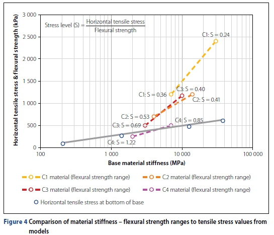
The stress level ranged from a minimum of 0.24 for C1 materials to a maximum of 1.22 for C4 materials, with the number of cycles that can be endured decreasing as the strength decreased. The fatigue life of cemented materials loaded to a stress level under 0.50 is generally good, being able to absorb millions of load cycles (Xie et al 2018). For the three-layer pavement system modelled using 3D LE FE, the stress levels calculated for the base layer underneath a 50 mm HS-SFRC layer indicated that C1 and C2 materials would perform well under 80 kN axle loads. C3 and C4 materials would deteriorate faster.
Figure 5 shows the effect of increasing the base material stiffness on the deflection bowl, where the concrete layer and base start acting as one layer and the deflection bowl shape becomes similar to that of the thick concrete layer models.

The LE FE analysis showed that the inclusion of cement-stabilised granular material would reduce all critical parameters. However, this analysis does not capture the possibility of the cemented material cracking due to material and traffic-loading variability. The effect of discretely cracked C1 and C2 materials underneath a 50 mm HS-SFRC layer could be detrimental to the layer underneath it, because cemented layer crack edges may cause stress concentrations in the adjacent layers. Physical modelling and FE modelling, that incorporates advanced material models for cemented granular materials, should be used to further investigate the use of cement-stabilised granular materials underneath thin concrete layers. Further investigations should also incorporate the repeated loading of traffic into numerical analyses.
CONCLUSION
Increasing the HS-SFRC layer thickness reduced all the critical parameters. The effect of including bound granular material, in the form of cement-stabilised granular material, was investigated by varying the base material stiffness over a wider range. By doing this the relative stiffness was varied. Increasing the base material stiffness reduced all the critical parameters. It was found that there was a logarithmic relationship between the tensile stress at the bottom of the base layer and base material stiffness. The linear elastic finite element modelling suggests that cemented bases underneath a 50 mm HS-SFRC layer that use C1 and C2 materials would perform well under standard axle loads of 80 kN, because the stress level they are subjected to is relatively low. The stress level of C3 and C4 materials was higher and these materials are more likely to deteriorate faster underneath a 50 mm HS-SFRC layer.
According to the LE FE modelling done, the incorporation of cement-stabilised bases would reduce all the critical parameters, and the stress levels in the base would fall within acceptable ranges. However, the possibility of the cement-stabilised material cracking due to material variability and/or overloading should be taken into consideration before a conclusion can be made of cemented base usefulness. If C1 or C2 materials are used underneath a 50 mm HS-SFRC layer and the cemented layer does crack discreetly, the unbound granular layer of subgrade underneath it will be subjected to stress concentrations.
As pavement design is a process intended to find the most economical combination of layer thickness and material types for pavements during the service life of the road, it is of concern that the high-tensile-strength capacity of the HS-SFRC does not seem to be utilised to its full potential when the thin concrete layer is supported by a stiff supporting layer.
The use of cement-stabilised base in UTCRCP should thus be further investigated to ensure that the most economical combination of materials is used in UTCRCP. Advanced material models for cement-stabilised granular materials should be used to verify the behaviour of cemented bases directly underneath thin HS-SFRC layers.
REFERENCES
Bredenhann, S, Van Heerden, J, Strauss, P & Joubert, P 2018. Design and construction of Ultra-Thin Continuously Reinforced Concrete (UTCRC) on N1 near Hugenot Tunnel. Proceedings, International Conference on Concrete Repair, Rehabilitation and Retrofitting, 31 October 2018, Cape Town. MATEC Web Conference, Vol 199. [ Links ]
Briggs, M A, Valsangkar, A J & Thompson, A 2016. Behaviour of fibre-reinforced concrete beams on grade. International Journal of Physiscal Modeling in Geotechnics, 16(4): 152-159. [ Links ]
Brown, S F & Selig, E T 1991. The design of pavement and rail track foundations. In O'Reilly, M P & Brown, S F (Eds). Cyclic Loading of Soils: From Theory to Design, 1st ed. London: Blackie, pp 249-305. [ Links ]
Burmister, D M 1945. The general theory of stresses and displacements in layered systems I. Journal of Applied Physics, 16 (February): 89-95. doi.org/10.1063/1.1707558. [ Links ]
Chen, D H, Won, M, Chen, X & Zhou, W 2016. Design improvements to enhance the performance of thin and ultra-thin concrete overlays in Texas. Construction and Building Materials, 116(July): 1-14. [ Links ]
Cho, Y-H, McCullough, B F & Weissmann, J 1996. Considerations on finite-element method application in pavements. Transportation Research Record, 1539(1): 96-101. [ Links ]
Dassault Systemes Simulia Corp 2016. ABAQUS. Mayfield Heights, OH: Simulia Corp. [ Links ]
De Beer, M 1990. Aspects of the design and behaviour of road structures incorporating lightly cementitious layers. PhD Thesis. University of Pretoria. [ Links ]
Department of Transport (DoT) 1979. TMH 1: Standard Methods of Testing Road Construction Materials, Method A14. Pretoria: DoT. [ Links ]
Department of Transport 1986. TRH13:Cementitious Stabilizers in Road Construction. Pretoria: DoT. [ Links ]
Department of Transport 1996. TRH 4: Structural Design of Flexible Pavements for Interurban and Rural Roads. Pretoria: DoT. [ Links ]
Denneman, E 2011. Fracture in high performance fibre reinforced concrete pavement materials. PhD Thesis. University of Pretoria. [ Links ]
Domone, P & Illston, J 2010. Construction Materials, 4th ed. Abingdon, UK: Spon Press. [ Links ]
Elsaigh, W A 2007. Modelling the behaviour of steel fibre reinforced concrete pavements. PhD Thesis. University of Pretoria. [ Links ]
Huang, Y H 1993. Pavement Analysis and Design, 2nd ed. Englewood Cliffs, NJ: Pearson Prentice Hall. [ Links ]
Ioannides, A M 2006. Concrete pavement analysis: The first eighty years. International Journal of Pavement Engineering, 7(4): 233-249. [ Links ]
Jordaan, G J 1984. Bituminous pavement rehabilitation design. Master's dissertation. University of Pretoria. [ Links ]
Kannemeyer, L, Perrie, B D, Strauss, P J & Du Plessis, L 2007. Ultra-thin continuously reinforced concrete pavement research in South Africa. Proceedings, International Conference on Concrete Roads, 16-17 August 2007, Midrand, South Africa. Cement & Concrete Institute report, pp 97-124. [ Links ]
Kearsley, E P & Mostert, H F 2010. Enabling the effective use of high-performance fibre reinforced concrete in infrastructure. In Van Zijl, G P A G & Boshoff, W P (Eds). Advances in Cement-Based Materials. London: CRC Press, pp 53-58. [ Links ]
Kearsley, E P, Steyn, W J VdM & Jacobsz, S W 2014. Centrifuge modelling of Ultra Thin Continuously Reinforced Concrete Pavements (UTCRCP). In Gaudin, C & White D (Eds). Proceedings, 8th International Conference, Physical Modelling in Geotechnics, 14-17 January 2014, Perth, Australia: Taylor & Francis, pp 1101-1106. [ Links ]
Kim, M 2007. Three-dimensional finite element analysis of flexible pavements considering nonlinear pavement foundation behaviour. PhD Thesis. University of Illinois at Urbana-Champa ign, US. [ Links ]
Lv, S, Xia, C, Liu, H, You, L, Qu, F, Zhong, W et al 2021. Strength and fatigue performance for cement-treated aggregate base materials. International Journal of Pavement Engineering, 22(6): 690-699. https://www-tandfonline-com.uplib.idm.oclc.org/doi/full/10.1080/10298436.2019.1634808. [ Links ]
MacDonald, B J 2011. Practical Stress Analysis with Finite Elements, 2nd ed. Dublin, Ireland: Glasnevin Publishing. [ Links ]
Neville, A M & Brooks, J J 2010. Concrete Technology, 2nd ed. Harlow, UK: Pearson. [ Links ]
O'Flaherty, C A 1967. Highway Engineering. 2nd ed., Volume II. London: Edward Arnold. [ Links ]
Pereira, D D S, Balbo, J T & Khazanovich, L 2006. Theoretical and field evaluation of interaction between ultra-thin whitetopping and existing asphalt pavement. International Jounral of Pavement Engineering, 7(4): 251-260. [ Links ]
Rao, S & Roesler, J R 2005. Characterization of effective built-in curling and concrete pavement cracking on the Palmdale test sections. Working paper. Davis, CA: University of California, Davis Institute of Transportation Studies. [ Links ]
SABITA (South African Bitumen and Tar Association) 1993. GEMS - The design and use of granular emulsion mixes. Cape Town: South African Bitumen and Tar Association. [ Links ]
SANRAL (South African National Roads Agency Limited) 2013. Pavement design. In South African Pavement Engineering Manual. Pretoria: SANRAL. [ Links ]
Visser, A 2017. Potential of South African road technology for application in China. Journal of Traffic and Transportation Engineering (English Ed), 4(2): 113-117. [ Links ]
Werkmeister, S, Dawson, A R & Wellner, F 2004. Pavement design model for unbound granular materials. Journal of Transportation Engineering, 130(5): 665-674. [ Links ]
Xie, J, Tang, L, Lv, S, Zhang, N, Huang, T & Liu, H 2018. Standardization of fatigue characteristics of cement-treated aggregate base materials under different stress states. Applied Sciences, 8: 1-23. [ Links ]
 Correspondence:
M S Smit
Department of Civil Engineering University of Pretoria
Pretoria, 0002, South Africa
T: +27 12 42 0 2179; E: phia.smit@up.ac.za
E P Kearsley
Department of Civil Engineering University of Pretoria
Pretoria, 0002, South Africa
T: +27 12 42 0 2176; E: elsabe.kearsley@up.ac.za

PHIA SMIT (MSAICE) received her BEng in Civil Engineering from the University of Pretoria in 2012. This paper is based on the research done for her PhD at the University of Pretoria. She is currently employed as a lecturer at the same university, and her fields of interest are concrete technology, pavement engineering and soil-structure interaction.

PROF ELSABÉ KEARSLEY (Pr Eng, FSAICE) graduated with a degree in Civil Engineering from the University of Pretoria in 1984, and she holds a PhD from the University of Leeds. She worked as a Structural Design Engineer in both South Africa and the United Kingdom before joining the staff in the Department of Civil Engineering at the University of Pretoria. For the last 26 years she has been involved with cement and concrete materials research. In 2009 she served as President of the South African Institution of Civil Engineering (SAICE).

