


Services on Demand
Article
 English (pdf)
 Article in xml format
 Article references
Indicators

Related links
-
 Cited by Google
 -
 Similars in Google
Share

 Permalink
Journal of the South African Institution of Civil Engineering
On-line version ISSN 2309-8775
Print version ISSN 1021-2019
J. S. Afr. Inst. Civ. Eng. vol.63 n.3 Midrand Sep. 2021
http://dx.doi.org/10.17159/2309-8775/2021/v63n3a3
TECHNICAL PAPER
A parametric design process model for box culverts
N Ngobeni; A L Marnewick; D J Van Vuuren
ABSTRACT
This research proposes a parametric design process model to improve the structural engineering project team performance by automating the design and three-dimensional modelling procedures of box culverts. Although standardised design procedures can reduce the design time of repetitive structures such as box culverts, the increased time and effort required for revising construction drawings negatively impacts a project's performance. A literature review was conducted to develop a theoretical process model to improve the current structural design optimisation and three-dimensional modelling procedures of box culverts. The proposed process model was validated using structured interviews with professionally registered structural engineers for appropriateness to box culverts and the potential to improve project performance. The data analysis revealed that the interviewed engineers were in favour of automating the design optimisation and three-dimensional modelling procedures of box culverts. Moreover, parametric design automation would result in improved project performance when encountering an inevitable design change. However, the user's control over the output of each process should not be discarded. This study can help readers understand the transformation of the structural design and three-dimensional modelling procedures of repetitive structures, such as box culverts, into an algorithmic form to achieve improved project performance.
Keywords: parametric design, automation, culvert, BIM, 3D modelling, design optimisation
INTRODUCTION
The introduction of building information modelling (BIM) and parametric design methods has improved the implementation of processes in the traditional structural engineering workflow. Structural engineering processes previously completed in sequential and isolated steps (Bhusar & Akhare 2014; Romo et al 2015) can now be automated through BIM parametric design (Gilkinson et al 2015; Kalkan et al 2018). Surveys conducted by Hamidavi et al (2020) have revealed that more than 60% of structural engineers in the United Kingdom (UK) who are professionally accredited with the Institution of Structural Engineers (IStructE), Institution of Civil Engineers (ICE), and the American Society of Civil Engineers (ASCE) believe in the potential of automation to resolve the challenges faced in structural engineering. Hence, automating the cumbersome and time-consuming manual processes for simple and repetitive structures can reduce the time spent on the project while minimising effort. Box culverts are an example of simple, repetitive structures which can benefit from parametric design automation (Manmeetsingh & Julian 2016). Standardisation of design procedures has improved the manual structural design process of box culverts. For instance, the design procedure prescribed in the Design Manual for Standard Box Culverts (National Transport Commission 1981) allows for selecting a box culvert's geometric and material properties with minimal effort. However, producing construction drawings for the designed box culvert remains a labour-intensive process of the traditional workflow (Bhusar & Akhare 2014).
Although existing literature aimed at automating either the traditional structural design or two-dimensional (2D) computer-aided design (CAD) drawing procedures of box culverts was evident, literature for integrating and automating the structural design optimisation and three-dimensional (3D) modelling procedures for box culverts was limited. This study therefore aims to evaluate the potential of reducing the time and effort required to perform re-work following a design change for box culverts, thereby improving project performance. Moreover, this study will assist by contributing to the current body of knowledge regarding the expected benefits of integrating and automating the structural design optimisation and 3D modelling procedures for box culverts. The following sections present the literature review, whereby the initial parametric design model is developed, followed by the results from the structured interview findings, where after the findings are then used to validate the proposed parametric design process model for box culverts.
LITERATURE REVIEW
Road construction projects consist of various types of transportation structures, such as bridges and culverts. The infrastructure choice depends on the stakeholder's requirements and influence from the project environment. For instance, box culverts are generally used in road construction where watercourses, such as streams, are located at a level significantly lower than the final road level (Manmeetsingh & Julian 2016). Since both culverts and bridges often serve the same purpose, culverts are generally preferred as more affordable alternatives over bridges, due to their significantly lower construction costs (Parry et al 2000). Furthermore, the regulations governing the design of culvert structures are similar to those of bridges, since both structures are expected to support traffic loads (Ahmed & Alarabi 2011).
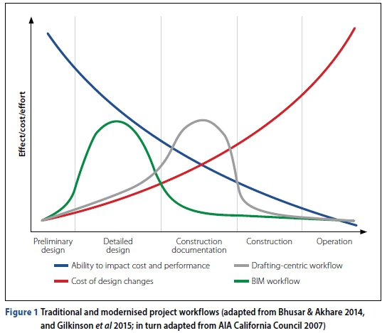
Recent advances in information technology have increased the number of tools available for completing the design and drawing processes, thereby improving the traditional structural engineering workflows. For instance, Bhusar and Akhare (2014) and Gilkinson et al (2015) compared the effects of implementing the traditional 2D drafting-centric workflow with the modernised 3D BIM workflow. Figure 1 shows that the effort required on a project implementing a traditional workflow (indicated by the grey line in the figure) steadily increases from the early design phases to a maximum during the construction documentation stage (Bhusar & Akhare 2014; Gilkinson et al 2015). Conversely, the effort required for implementing the modernised BIM workflow (indicated by the green line) significantly increases to a maximum during the early stages of a project, since the design and 3D modelling processes are linked through automation (Gilkinson et al 2015; Kalkan et al 2018). Implementation of the BIM workflow is beneficial to a project since the potential to impact the project cost and performance is at a maximum at the start of the project (Bhusar & Akhare 2014; Gilkinson et al 2015). Moreover, any changes implemented during the early design phases result in low-cost implications for the project's budget (Bhusar & Akhare 2014; Gilkinson et al 2015). The high potential to impact the project cost and performance, and the low cost of design changes earlier in the project allow the engineer to optimise a design with less risk (Alwisy et al 2012).
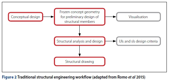
According to Romo et al (2015), the typical structural engineering workflow shown in Figure 2 first requires the development of a concept for the structural system. Predetermined standards within an organisation (i.e. the span-to-depth ratio rules) (Brishami et al 2018) and simplified analysis calculation procedures (i.e. culvert design coefficient tables) (Reynolds et al 2007) are often used to develop the conceptual structural system. Depending on the preferred structural analysis tool, a 3D finite element analysis (FEA) model can be generated to visualise the preliminary design geometry for correctness (Romo et al 2015). Moreover, the preference of FEA tools is based on the ability to produce accurate and realistic analysis results, which may lead to a more economical design. For instance, Kang et al (2008). Zhu et al (2012) and Ulger et al (2020) were able to simulate the loading effects caused by relative settlement of surrounding soils on a culvert for trenched and un-trenched installation conditions. The results observed by Kang et al (2008), Zhu et al (2012) and Ulger et al (2020) revealed that the simulated loads imposed on the structure were greater for un-trenched installation in comparison to trenched conditions.
A culvert is analysed and designed according to the design loading criteria that are specified by the country's design regulations (Ahmed & Alarabi 2011; Manmeetsingh & Julian 2016). Design regulations such as the Technical Manual for Highways (TMH7) (Committee of State Road Authorities 1981), BS 5400 (BS 1978) and BD 31/01 (The Highways Agency 2001) require designers to consider the behaviour of structures under the ultimate and serviceability limit states. Serviceability limit states focus on the state of the structure under normal operational conditions, while ultimate limit states are more concerned with the failure modes of the individual structural members (Committee of State Road Authorities 1981; Dawe 2003).
Once the preliminary structural system is concluded, the design can thereafter be optimised and communicated through structural construction drawings (Romo et al 2015). Communication of the design intent requires a geometric model to be produced and coordinated with the other disciplines (Solnosky 2017). According to Senescu et al (2006), the production of a BIM model for drawing purposes is often carried out by a BIM manager. Furthermore, production of a 3D model in a BIM environment takes significantly less time and effort compared to traditional CAD tools (Senescu et al 2006).
Despite the apparent benefits associated with intelligent BIM tools, several challenges are highlighted in the existing literature. Since the early design information received from the civil and geotechnical engineers (Nicholson 2014) is prone to changes (Rempling et al 2019), the structural engineer might often need to perform re-work due to inevitable changes to the design input data (Bhusar & Akhare 2014; Gilkinson et al 2015). Traditionally, construction drawings were produced manually in 2D, which requires more effort to update the drawing separately following the need for design changes (Mangal & Cheng 2018). Moreover, coordination using 2D drawings caused challenges in visualising the design intent (Mangal & Cheng 2018). Although modernised project delivery methods enforce early involvement of project stakeholders to improve the coordination and early decision-making processes (Rempling et al 2019), data exchange between various BIM tools (interoperability) can cause challenges in coordination of information (Lothar 2017). Several authors have evaluated the use of the neutral IFC (Industry Foundation Class) data format to resolve interoperability challenges. According to (Lothar 2017), interoperability by IFC2x3 is based on intelligent data formats, which allow for 3D model presentation, material extraction, and structural analysis and design. However, when evaluating the use of IFC format as a mediator for data transfer on various software packages, Ran et al (2018) discovered that Computers and Structures Inc (CSI) ETABS and SAP2000 were able to import data in less time than Autodesk Robot Structural Analysis (RSA). However, certain properties required manual input after importing the IFC file on ETABS and SAP2000, and material properties were missing after importing the IFC file on RSA. Similarly, an investigation by Shoieb et al (2020) revealed that, although material properties could be imported from ETABS and SAP2000 to RSA, loads could not be imported into RSA from all structural analysis software packages evaluated.
According to Shoieb et al (2020), ETABS and SAP2000 are capable of high interoperability due to the unique supplier of the two applications, and having implementation agreements for information exchange.
Despite the importance of a good preliminary design, limited time is often allocated to the early design phase (Romo et al 2015). For instance, the additional time required to amend and re-analyse an analysis model following receipt of undesired results might not be allocated to the project budget (Romo et al 2015). Similarly, project time constraints also affect the optimisation of a design solution to achieve specific outcomes. According to Mangal and Cheng (2018), the design optimisation process of reinforced concrete frames is either performed manually or semi-automated using computational tools. However, Manmeetsingh and Julian (2016) advised that semi-automated tools, such as calculation spreadsheets, still require manual input, which makes the approach error-prone and time-consuming. Despite the ability of FEA computational tools to simulate realistic loading effects on a structure, the tools do not perform any multi-criteria decision analysis to achieve an optimal design solution (Mangal & Cheng 2018). For instance, standard FEA tools only analyse and propose one design solution (based on a single set of input parameters) instead of evaluating several alternatives (Mangal & Cheng 2018).
Existing literature recommends that early automation of the design and drawing processes would help alleviate the challenges faced in structural engineering. For instance, Hamidavi et al (2020) advise that automation solutions are more practical during the early design phase of a project, because designers can better influence the performance and cost of the project (Bhusar & Akhare 2014; Gilkinson et al 2015). Similarly, Holzer (2015) states that exploring the automation capabilities of parametric design algorithms may provide engineers with possibilities of manipulating BIM data with more flexibility during early project stages. Parametric design techniques are rapidly emerging as agile tools for evaluating various design alternatives with minimal effort (Romo et al 2015), and limited computer programming skills (Betancourt et al 2014; Hamidavi et al 2020). Moreover, the use of parametric design is a double-edged tool, since the automation tool can either be used during early project phases to evaluate alternative design solutions (Romo et al 2015), or for optimisation purposes by setting out specific design-related target outputs (Romo et al 2015; Hamidavi et al 2020).
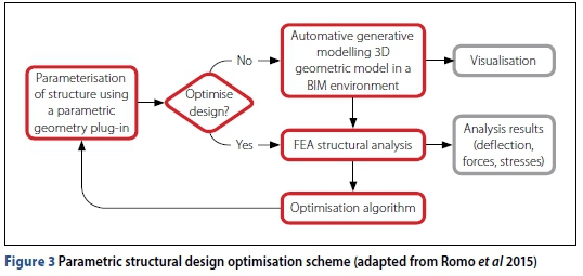
Romo et al (2015) and Hamidavi et al (2020) have recently proposed parametric design algorithms for design optimisation during the early project phases. The parametric structural design optimisation scheme proposed by Romo et al (2015) in Figure 3 shows that, once the structural model is parameterised through a visual programming plug-in, the design process starts by automatically generating a 3D geometric and analytical model in a BIM environment (Romo et al 2015). The 3D models are generated through a visual programming algorithm editor, which allows the designer to develop generative algorithms for automatically modelling the 3D geometry in both the BIM (Romo et al 2015) and FEA environments (Hamidavi et al 2020).
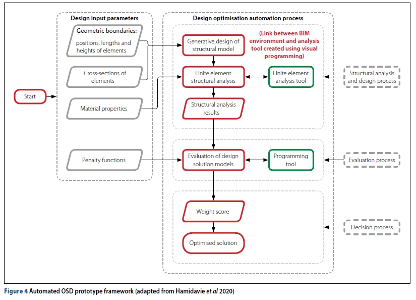
Similarly, the optimised structural design (OSD) framework proposed by Hamidavi et al (2020) also uses a combination of several BIM tools. In Figure 4 the automated design optimisation computational process consists of three sub-processes: (1) structural analysis and design, (2) evaluation of design solutions, and (3) multi-criteria decision analysis. According to Hamidavi et al (2020), integration of the BIM environment and an FEA tool is made possible through visual programming, which resolves the challenges related to BIM data transfer. According to Hamidavi et al (2020), visual programming tools allow the designer to link the design input parameters from the BIM information received with the structural FEA model. Moreover, the link created between the design input parameters enables the designer to automatically create an analysis model within an FEA tool - this ensures that any changes made to the information previously received are automatically applied to the optimised FEA model (Hamidavi et al 2020). For each analysis model created through generative design, the design loading conditions are automatically defined using the visual programming tool. Using the analysis results obtained for each FEA model, the evaluation process is conducted to evaluate various design solutions and, thereafter, perform multi-criteria decision analysis for each of the models generated (Hamidavi et al 2020). The analysis results are classified in terms of over-design and under-design based on a predefined weighting score system (Hamidavi et al 2020).
According to Omoregie and Turnbull (2016), the introduction of BIM has made it possible to produce intelligent models for construction documentation. Furthermore, the use of 3D models helps professional teams better illustrate their design intent and visualise the full structure before construction (Omoregie & Turnbull 2016). One of the advantages of using a BIM 3D model for producing drawings, instead of the traditional 2D CAD, is the ability for the BIM software to detect model member clashes across all disciplines (Jaehyun & Hubo 2015). According to Romo et al (2015), visual programming platforms are usually pre-integrated within parent BIM environments. The visual programming software plug-ins allow users to automatically generate and manipulate 3D BIM geometry by creating generative parametric algorithms (Romo et al 2015). Similarly, Juhee et al (2019) have developed an algorithm automating the BIM model generation process by using design parameters. Moreover, Juhee et al (2019) advise that the proposed modelling automation algorithm can shorten the requisite time for modelling, regardless of the type of work.
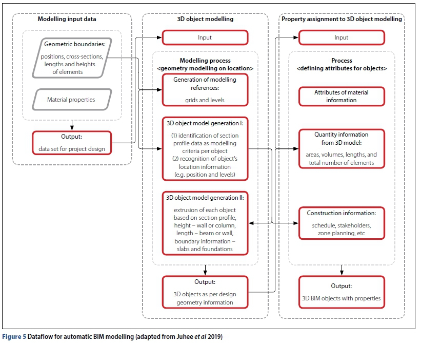
Figure 5 shows that the automated process of modelling 3D geometry based on the construction setting out information is enabled by the use of reference grids and level information (Juhee et al 2019). Using the object's location information and geometric attributes, the modelling process generates the 3D geometry based on the extrusion lengths and heights of each model component (Juhee et al 2019). According to Juhee et al (2019), extrusion of each component is based on the sectional profile. For instance, objects such as walls and columns would be extruded vertically (height), whereas beams would be extruded horizontally (length) (Juhee et al 2019). Once the 3D object has been generated, the material properties defined at the start of the automation process are assigned to the appropriate model components. Relevant construction information, such as material quantities, is thereafter accessible to produce construction drawings (Juhee et al 2019).
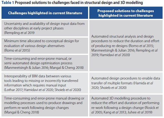
Table 1 summarises the challenges currently faced in structural design and 3D modelling, contributing to the amount of time and effort required to perform re-work in the event of an inevitable design change. Furthermore, the literature review findings given in Table 1 propose that automating the design and 3D modelling processes would resolve the issues currently faced in structural design and 3D modelling processes.
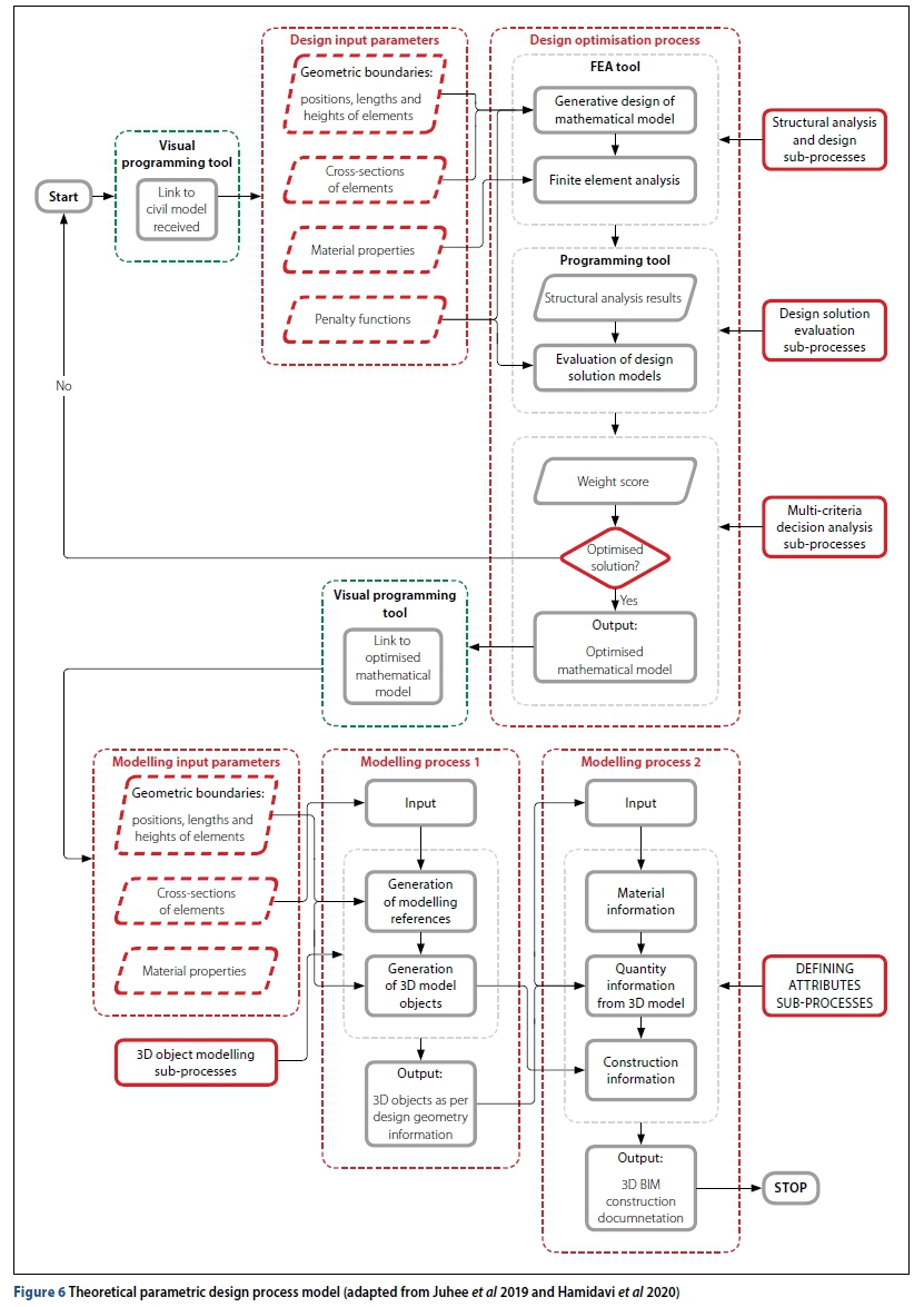
Hence, the theoretical parametric design process model shown in Figure 6 was proposed to resolve the challenges faced in structural engineering, thereby reducing the effort and time required to perform re-work for box culverts. The proposed theoretical model for automating the structural design and 3D modelling processes of box culverts was formed by a combination of:
1. The OSD framework proposed by Hamidavi et al (2020) for use on a wide range of structural design scenarios including bridge design.
2. The automated BIM model generation framework proposed by Juhee et al (2019) to shorten the requisite time for modelling, regardless of the type of work.
METHOD
Although the automated OSD and BIM 3D modelling algorithms were developed and validated for a wide range of applications in structural design and 3D modelling, the combination of the two algorithms required validation for appropriateness to box culverts. Therefore, this study's research design method was aimed at validating the theoretical model proposed in Figure 6 According to Axinn et al (2009), developing a research design begins with the selection of a unit of analysis, such as the interpretations of individuals or groups regarding a specific phenomenon. For this study, the interpretations of professionally registered structural engineers and 3D modellers were used to evaluate whether the proposed theoretical model would result in improved project performance. Responses from each participant were recorded on a standardised interview schedule and audio-recorder for validation purposes. To preserve anonymity for the interview participants, no personal information was transcribed when validating the collected data. Due to the COVID-19 restrictions at the time of this study, the structured interview process was conducted through a web-based meeting platform. The structured interview data collection method enabled the combined characteristics of qualitative and quantitative methods, which are useful for implementation of complex evidence-based research (Cooksey & McDonald 2019). To ensure that interpretations of both structural designers and 3D modellers were obtained, the sample size consisted of six participants who were professionally registered structural engineers with 3D modelling experience, and one professionally registered structural engineer. The composition of the interview participants with their respective professional backgrounds is shown in Table 2
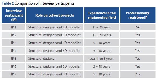
The interview participants IP 5 and IP 7 work in the same design office, whereas the remaining five participants work in different offices. While adhering to the university's ethical requirements, the interview participants were sourced as follows:
■ IPs 4, 5, and 7 - by previous industry interaction
■ IPs 3 and 6 - by LinkedIn requests (no previous interaction with IPs)
■ IP 2 - by request sent to the South African Institution of Civil Engineering (SAICE) young members communication group (no previous interaction with IP)
■ IP 1 - by recommendation from industry peer (no previous interaction with IP).
DISCUSSION
The proposed theoretical process model presented in Figure 6 was validated for use on box culverts in four parts:
1. Appropriateness of the proposed structural design and 3D modelling input parameters
2. Appropriateness of the proposed structural design and 3D modelling processes and sub-processes
3. Appropriateness of the proposed sequence of processes
4. Willingness of the participants to automate the proposed sub-processes to reduce the time and effort required to perform re-work.
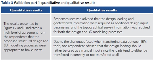
Although the structured interview results presented in Table 3 are in favour of the proposed input parameters, the results also highlighted the need for additional input parameters.
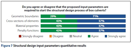
Therefore, the results shown in Figure 7 validate that, if implemented correctly, the proposed structural design input parameters are appropriate for use on box culverts.
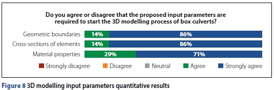
Moreover, the results shown in Figure 8 validate that, if implemented correctly, the proposed 3D modelling input parameters are appropriate for use on box culverts.
The request received from the respondents to include additional input parameters was mainly due to the specialised nature and functionality of transportation structures. Box culverts are used in road construction to support traffic loads while providing drainage for streams positioned at a level significantly lower than the final road level (Manmeetsingh & Julian 2016). Communication of the design intent requires a structural drawing to be produced and coordinated with other disciplines (i.e. the civil engineer) (Solnosky 2017). Hence, survey information such as the road and drainage levels would be required on the structural drawings to illustrate the structure's position in relation to the road, natural ground, and stormwater drainage levels. The position of a culvert in relation to the road and natural ground level can have positive or negative effects on the structure. For instance, the traffic load effects are reduced as the distance between the road level and culvert structure (soil cover height) increases (Ahmed & Alarabi 2011). However, the soil dead load imposed on the culvert roof also increases with each increase in cover height (Ahmed & Alarabi 2011).
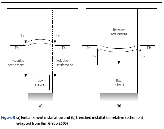
Similarly, the position of the culvert in relation to the natural ground level determines the installation method, which also affects the design loading. For the embankment (un-trenched) installation method in Figure 9(a), the surrounding soils have higher settlement rates in comparison to the soil directly above the structure - which results in the surrounding soils increasing the total load applied to the culvert (Kim & Yoo 2005; Kang et al 2008; McGuigan & Valsangkar 2011; Wood et al 2015). Relating to the trenched method shown in Figure 9(b), the surrounding soils have lower settlement rates compared to the soil directly above the structure - resulting in the surrounding soils reducing the total load applied to the structure (Kim & Yoo 2005; Kang et al 2008; McGuigan & Valsangkar 2011; Wood et al 2015). According to Ulger et al 2020, the soil parameters provided within the geotechnical report can be used to realistically simulate soil-structure interaction effects on FEA tools.
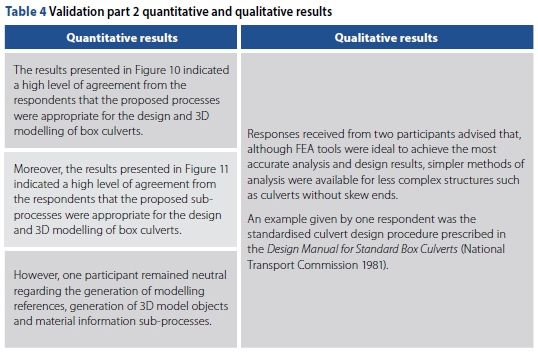
The structured interview results presented in Table 4 are in favour of the proposed structural design and 3D modelling processes and sub-processes. However, the results advise that, although FEA tools are more effective in providing accurate results, simpler forms of analysis are available.
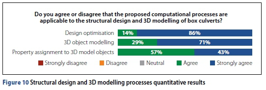
The results shown in Figures 10 therefore validate that, if implemented correctly, the proposed structural design and 3D modelling processes are appropriate for use on box culverts.
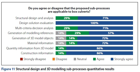
The results shown in Figure 11 furthermore validate that, if implemented correctly, the proposed structural design and 3D modelling sub-processes are appropriate to use on box culverts.
The literature review findings also confirmed that simplified analysis methods were evident. For example, the culvert design coefficient tables (Reynolds et al 2007) and the Design Manual for Standard Box Culverts (National Transport Commission 1981) are available for the design of culverts, with less effort. However, several researchers have proven that FEA tools were capable of simulating realistic load effects to produce more economical structural designs at faster rates in comparison to simplified analysis procedures. For instance, Ulger et al (2020), Zhu et al (2012) and Kang et al (2008), have used an FEA tool to simulate the realistic loading effects caused by the trenched and untrenched installation methods. Furthermore, Mangal and Cheng (2018) advised that the preference of using FEA tools is based on the time and effort benefits experienced when performing structural designs.
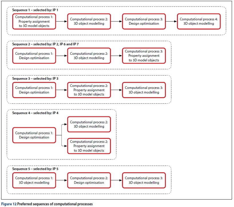
When asked to confirm the appropriateness of the proposed sequence of processes (validation part 3), three (43%) of the respondents agreed that the proposed sequence was also appropriate for the design and 3D modelling of box culverts. However, the remaining (57%) respondents each preferred four different sequences of processes. The five preferred sequences of computational processes derived from the interview responses received are presented in Figure 12
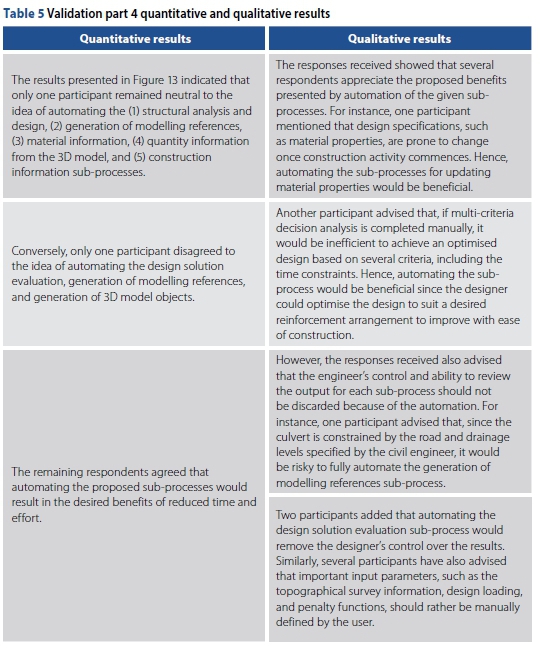
Regarding Table 5 - most of the respondents were in favour of automating the structural design and 3D modelling sub-processes to achieve the benefits of reduced time and effort when performing re-work on culvert projects. In addition, the possibility to automatically update input parameters prone to change, and perform multi-criteria decision analysis, were suggested as additional potential benefits to the user. However, the qualitative results showed some reluctance amongst the participants to fully automate the proposed process model through parametric design. The reluctance to fully automate the design and 3D modelling sub-processes was based on the expected reduction in control that the user would have, and the possibility of encountering construction-related problems caused by:
■ Non-adherence to non-structural requirements constraining the culvert geometry and position.
■ Limited engineering judgement applied when evaluating design solutions.
■ Unsuccessful transfer of design loading information.
As a possible solution for the reluctance of fully automating the sub-processes, it was suggested that a user should be allowed to review and manually modify the output of each sub-process. Allowing the user to retain some control over each process and important input parameters would assist in reducing the level of reluctance amongst the interview respondents.
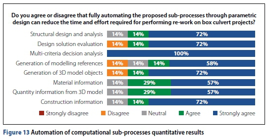
Therefore, the results shown in Figure 13 validate that, if implement correctly, automating the proposed structural design and 3D modelling processes could result in reduced effort when performing re-work for box culverts.
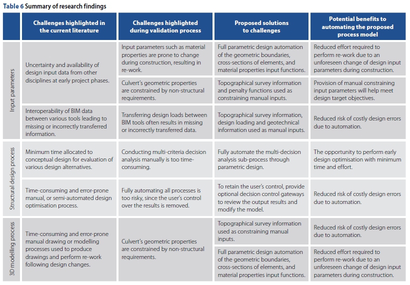
In summary, some similarities were drawn from the literature review and structured interview findings. The quantitative results received from the structured interview process revealed that the majority of the participants agreed that the proposed process model was appropriate for use on box culverts. Furthermore, automating the proposed process model through parametric design could potentially yield benefits which would help improve project performance. However, certain challenges associated with automation of processes and parameters constrained by important structural and non-structural requirements were raised. Table 6 provides a brief comparison between the literature review and validation process findings.
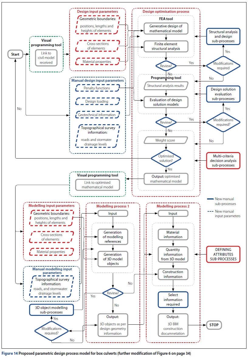
Therefore, the initially proposed theoretical model presented in Figure 6 was revised, based on the validation process findings, which recommend additional manual input parameters and decision gateways, with the option to review and perform manual alterations. The revised and validated process model is presented in Figure 14 whereby the new manual processes and input parameters are shown in blue. The sequence of computational processes remained unchanged since most of the interview participants approved the originally proposed sequence of processes.
The parametric design process model shown in Figure 14 creates a visual programming link to the civil engineer's 3D model for extraction of relevant constraining design information such as the opening size, flange and rib thicknesses of members and material properties (Hamidavi et al 2020). Constraining input parameters such as (1) penalty functions to achieve optimised solutions based on predefined design targets adhering to constraining factors (Nicholson 2014), (2) design loading caused by fill heights, design regulations and client's requirements (Dawe 2003; Ahmed & Alarabi 2011; Manmeetsingh & Julian 2016), (3) geotechnical information such as soil properties (Nicholson 2014), and (4) road and stormwater drainage topographical survey levels are manually captured by the user (Nicholson 2014; Manmeetsingh & Julian 2016). Thereafter, all design input parameters are obtained, and multiple mathematical models are automatically developed. For each mathematical model generated, FEA and structural design are carried out and the results are, thereafter, stored in a database (Hamidavi et al 2020). The first decision gateway is presented as an option to review the stored results and perform manual modifications. Once satisfied with the results, the automated result evaluation process is completed (Hamidavi et al 2020), and the second decision gateway is presented to review the evaluation outcome. Once satisfied, the automated multi-criteria decision analysis process is completed, and the third decision gateway is presented to review the design optimisation output (Hamidavi et al 2020).
Once the user is satisfied that an optimal design solution is achieved, a visual programming link is once again created to extract relevant modelling input parameters from the optimised mathematical model to communicate the design intent (Nicholson 2014; Solnosky 2017; Juhee et al 2019). Concurrently, the topographical survey information, such as reference levels and coordinate systems, are manually defined as the 3D modelling input parameters required to start the 3D object modelling computational process (Nicholson 2014; Solnosky 2017). Subsequently, modelling references and 3D modelling objects are, thereafter, generated from the input parameters (Juhee et al 2019), and the fourth decision gateway is presented to review the output. Once satisfied, the material information for each member is assigned and the relevant quantity and construction information is extracted from the 3D objects containing the design material information (Juhee et al 2019). The final manual process provides an option for the user to select what construction documentation, such as drawings, should be generated.
CONCLUSION
Leveraging the computational strength of continuously improving BIM tools requires structural engineering project teams to adapt to the ongoing advances in technology. The proposed theoretical process model presented in Figure 6 was initially developed to evaluate the potential of reducing the time and effort required to perform re-work following a design change for box culverts. Hence, a proposed parametric design process model was developed from existing literature (that encompasses all the relevant challenges) to improve the structural engineering team performance and resolve the challenges faced in structural design and 3D modelling processes. The proposed process model was validated with professionally registered structural engineers and BIM 3D modellers for appropriateness to box culverts. The research findings revealed that, if implemented, the proposed theoretical process model presented in Figure 14 is capable of resolving the challenges faced of (1) uncertainty of design input parameters, (2) non-adherence to constraining requirements, (3) BIM interoperability, and (4) insufficient time allocated to early design phases. Hence, if implemented correctly, the proposed process model is capable of providing the users with the benefits of (1) performing re-work with minimal effort, (2) ensuring adherence to constraining requirements, (3) reduced risk of costly design errors, and (4) early design optimisation. However, due to their importance, the design loading, topographical survey information, and geotechnical information should be used as manual inputs to avoid costly errors. Moreover, an option should be provided to the designer to evaluate and modify (if required) the analysis model after exercising his/her engineering judgement. Due to time restrictions, the proposed theoretical process model could not be implemented, and the realised benefits could not be measured. Therefore, implementation and measurement of the realised benefits provided by the proposed parametric design process model for box culverts are suggested as an area for future research.
REFERENCES
Ahmed, A O M & Alarabi, E 2011. Development formulation for structural design of concrete box culverts. Practice Periodical on Structural Design and Construction, 16(2): 48-55. doi: 10.1061/(ASCE)SC.1943-5576.0000075. [ Links ]
AIA (American Institute of Architects) California Council 2007. Integrated project delivery: A guide. Sacramento, CA: AIA, pp 1-62. doi: 10.1016/j.autcon.2010.09.002. [ Links ]
Alwisy, A, Al-Hussein, M & Al-Jibouri S H 2012. BIM approach for automated drafting and design for modular construction manufacturing. Computing in Civil Engineering, 3(1): 221-228. doi:10.1061/9780784412343.0028. [ Links ]
Axinn, W G, Pearce, L D 2009. Fitting data collection methods to research aims. In: Mixed Method Data Collection Strategies. New York: Cambridge University Press, pp 28-53. doi: 10.1017/cbo9780511617898.003. [ Links ]
Betancourt, M C, Quintero, L M & Cereceda, G 2014. A discussion on algorithmic thinking in product design process. Proceedings, 13th International Design Conference, 19-23 May 2014, Dubrovik, Croatia, pp 1035-1042. [ Links ]
Bhusar, A A & Akhare, A R 2014. Application of BIM in structural engineering. SSRG International Journal of Civil Engineering, 1(5): 12-20. [ Links ]
Brishami, H, Wei, F, Yang, J, Zhang, Y & Zhong, C 2018. Design of reinforced concrete bridges. In: ICE Manual of Bridge Engineering. London, ICE Publishing, pp 1-314. doi:10.1680/mobe.34525.0185. [ Links ]
BS (British Standard) 1978. BS 5400-2: Steel, Concrete and Composite Bridges: Specifications for Loads. London: British Standards Institution. [ Links ]
Committee of State Road Authorities 1981. TMH7. Parts 1 and 2: Code of Practice for the Design of Highway Bridges and Culverts in South Africa. Pretoria: Department of Transport. [ Links ]
Cooksey, R & McDonald, G 2019. Surviving and Thriving in Postgraduate Research. Cham, Switzerland: Springer. doi: 10.1007/978-981-13-7747-1. [ Links ]
Dawe, P 2003 Limit state design. Chapter 4. In: Traffic Loading on Highway Bridges. London: Thomas Telford, pp 33-44. doi: 10.1680/tlohb.32415.0004. [ Links ]
Gilkinson, N, Raju, P, Kiviniemi, A & Chapman, C 2015. Building information modelling: The tide is turning. Proceedings of the Institution of Civil Engineers: Structures and Buildings, 168(2): 81-93. doi: 10.1680/stbu.12.00045. [ Links ]
Hamidavi, T, Abrishami, S, Ponterosso, P, Begg, D & Nanos, N 2020. OSD: A framework for the early stage parametric optimisation of the structural design in BIM-based platform. Construction Innovation, 20(2): 149-169. doi: 10.1108/CI-11-2019-0126. [ Links ]
Holzer, D 2015. BIM and parametric design in academia and practice: The changing context of knowledge acquisition and application in the digital age. International Journal of Architectural Computing, 13(1): 65-82. doi: 10.1260/1478-0771.13.1.65. [ Links ]
Jaehyun, P & Hubo, C 2015. Automatic construction schedule generation method through BIM model creation. Proceedings, 2015 International Workshop on Computing in Civil Engineering, 21-23 June 2015, Austin, TX, pp 620-627. doi:10.1061/9780784479247.077. [ Links ]
Juhee, R, Hyun-Soo, L & Moonseo, P 2019. Automated BIM model generation using drawing recognition and line-text extraction. Proceedings, ASCE International Conference on Computing in Civil Engineering, 17-19 June 2019, Atlanta, GA, pp 272-278. doi:10.1061/9780784482421.035. [ Links ]
Kalkan, E, Okur, F Y & Altuniçik, A C 2018. Applications and usability of parametric modeling. Journal of Construction Engineering, Management & Innovation, 1(3): 139-146. doi: 10.31462/jcemi.2018.03139146. [ Links ]
Kang, J H, Lho, B-C C & Choi, S-R R 2013. Parametric web-CAD for box culvert design. Computer-Aided Design and Applications, 1(1-4): 147-152. doi: 10.1080/16864360.2004.10738253. [ Links ]
Kang, J, Parker, F, Kang, Y J & Yoo, C H 2008. Effects of frictional forces acting on sidewalls of buried box culverts. International Journal for Numerical and Analytical Methods in Geomechanics, 32(3): 289-306. doi: 10.1002/nag.628. [ Links ]
Kim, K &Yoo, C H 2005. Design loading on deeply buried box culverts. Journal of Geotechnical and Geoenvironmental Engineering, 131(1): 20-27. doi: 10.1061/(ASCE)1090-0241(2005)131. [ Links ]
Lothar, H 2017. Nowadays structural engineering with the use of BIM technology. From 3D modeling, structural analysis, and design to structural system evolution: practitioner report. Proceedings, Structures Congress 2017, 6-8 April 2017, Denver, CO, pp 24-34. doi:10.1061/9780784480427.003. [ Links ]
Mangal, M & Cheng, J C P 2018. Automated optimization of steel reinforcement in RC building frames using building information modeling and hybrid genetic algorithm. Automation in Construction, 90(2018): 39-57. doi: 10.1016/j.autcon.2018.01.013. [ Links ]
Manmeetsingh, S & Julian, K 2016. Sustainable design automation for simple and repetitive structures. Proceedings, Construction Research Congress 2016, 31 May-2 June 2016, San Juan, Puerto Rico, pp 2633-2641. doi:10.1061/9780784479827.262. [ Links ]
McGuigan, B L & Valsangkar, A J 2011. Earth pressures on twin positive projecting and induced trench box culverts under high embankments. Canadian Geotechnical Journal, 48(2): 173-185. doi: 10.1139/T10-058. [ Links ]
National Transport Commission 1981. Design Manual for Standard Box Culverts. Book I - Design. Pretoria: Department of Transport. [ Links ]
Nicholson, T A 2014. Design and construction of A34 Wolvercote Highway viaduct replacement, UK. Proceedings of the Institution of Civil Engineers: Bridge Engineering, 167(2): 122-130. doi: 10.1680/bren.11.00006. [ Links ]
Omoregie, A & Turnbull, D E 2016. Highway infrastructure and building information modelling in the UK. Proceedings of the Institution of Civil Engineers: Municipal Engineer, 169(4): 220-232. doi: 10.1680/jmuen.15.00020. [ Links ]
Parry, J D, Brooks, D M, Jones, T E & Hewitt, N C 2000. A guide to small bridge design for highway engineers. Overseas Road Note 9. Crowthorne, UK: Transport Research Laboratory (TRL). [ Links ]
Ran, R, Jiansong, Z & Nicholas, D H 2018. BIM interoperability for structure analysis. Proceedings, Construction Research Congress 2018, 2-4 April 2018, New Orleans, LA, pp 470-479. doi:10.1061/9780784481264.046. [ Links ]
Rempling, R, Mathern, A, Tarazona Ramos, D & Luis Fernández, S 2019. Automatic structural design by a set-based parametric design method. Automation in Construction, 108(August): 102936. doi: 10.1016/j.autcon.2019.102936. [ Links ]
Reynolds, C E, Steedman, J C & Threlfall, A J 2007. Reynolds's Reinforced Concrete Designer's Handbook. Hoboken, NJ: Taylor & Francis. [ Links ]
Romo, J, Bögle, A & Meyboom, A 2015. Geometry and parametric modeling in the conceptual design of bridges. Proceedings, IABSE Conference - Structural Engineering: Providing Solutions to Global Challenges, 23-25 September 2015, Geneva, Switzerland, pp 433-442. doi: 10.2749/222137815818357403. [ Links ]
Rosick, M P, Mlynarski, M & Fitzgerald, J M 2005. Automation: From bridge design to contract drawings. Proceedings, Structures Congress 2005, 20-24 April 2005, New York, pp 1-12. doi: doi:10.1061/40753(171)174. [ Links ]
Senescu, R, Mole, A & Fresquez, A 2006. A case study in structural drafting: Analysis and design using an integrated intelligent model. Proceedings, Joint International Conference on Computing and Decision Making in Civil and Building Engineering, 14-16 April 2006, New York, pp 1797-1806. [ Links ]
Shoieb, K, Serror, M H & Marzouk, M 2020. Web-based tool for interoperability among structural analysis applications. Journal of Construction Engineering and Management, 146(6): 1-12. doi: 10.1061/(ASCE)CO.1943-7862.0001840. [ Links ]
Solnosky, R L 2017. Integrated structural processes on innovative multidisciplinary projects supported by building information modeling. Journal of Architectural Engineering, 23(2): 1-21. doi: 10.1061/(ASCE)AE.1943-5568.0000230. [ Links ]
The Highways Agency (UK) 2001. Design of buried concrete box and portal frame structures. Design Manual for Roads and Bridges (DMRB), Vol 2, Sect 2, Pt 12 (BD 31/01). Guildford, UK: The Highways Agency. [ Links ]
Ulger, T, Okeil, A M & Elshoura, A2020. Load testing and rating of cast-in-place concrete box culverts. Journal of Performance of Constructed Facilities, 34(2): 1-11. doi: 10.1061/(ASCE)CF.1943-5509.0001401. [ Links ]
Wood, T A, Lawson, W D, Jayawickrama, P W & Newhouse, C D 2015. Evaluation of production models for load rating reinforced concrete box culverts. Journal of Bridge Engineering, 20(1): 1-12. doi: 10.1061/(ASCE)BE.1943-5592.0000638. [ Links ]
Zhu, P, Liu, R, Liu, W & Wu, X 2012. Study on optimal design of a box-culvert under road. Proceedings, 2012 International Conference on Civil Engineering and Urban Planning, 18-20 August 2012, Yantai, China, pp 614-618. doi: 10.1061/9780784412435.110. [ Links ]
 Correspondence:
N Ngobeni
Postgraduate School of Engineering Management, University of Johannesburg
PO Box 524, Auckland Park 2006, Johannesburg, South Africa
T: +27 83 540 4174; E: nhlanhlangobeni@gmail.com
A L Marnewick
Postgraduate School of Engineering Management University of Johannesburg
PO Box 524, Auckland Park 2006, Johannesburg, South Africa
T: +27 11 559 1735; E: amarnewick@uj.ac.za
D J Van Vuuren
Engineering Augmented Degree Programme, School of Engineering, University of Pretoria
Private Bag X20, Hatfield 0028, Pretoria, South Africa
T: +27 72 445 1911; E: dirk.vanvuuren@up.ac.za

NHLANHLA NGOBENI holds an MPhil in Engineering Management, a BTech in Structural Engineering, and a Certified Associate Project Manager (CAPM) qualification attained from the Project Management Institute (PMI). He is currently a structural engineering technologist and project manager at MG Consulting Engineers.

PROF ANNLIZÉ MARNEWICK (Pr Eng) holds a D Ing and M Ing in Engineering Management, a B Ing Electrical and Electronic Engineering, as well as a BSc Hons in Applied Mathematics. She is currently an Associate Professor at the Postgraduate School of Engineering Management, University of Johannesburg, where she focuses on the supervision of research Master's and PhD students. Before joining academia, she worked in the industry for 14 years, specialising in requirements engineering.

DR DIRK JOHAN VAN VUUREN (Pr Eng) holds a PhD in Engineering Management, and an MEng and BEng in Mechanical Engineering. He is currently a lecturer at the School of Engineering, University of Pretoria, where he lectures modules and supervises Master's students. Before joining academia, he worked in the renewable energy industry.

