


Services on Demand
Article
 English (pdf)
 Article in xml format
 Article references
Indicators

Related links
-
 Cited by Google
 -
 Similars in Google
Share

 Permalink
Journal of the South African Institution of Civil Engineering
On-line version ISSN 2309-8775
Print version ISSN 1021-2019
J. S. Afr. Inst. Civ. Eng. vol.63 n.3 Midrand Sep. 2021
http://dx.doi.org/10.17159/2309-8775/2021/v63n3a2
TECHNICAL PAPER
Incipient motion of Armorflex articulating concrete blocks on steep slopes
K Delport; G R Basson; A Bosman
ABSTRACT
Armorflex is an articulating concrete block erosion protection measure that has been used as an alternative to riprap for many years. Even though extensive research and hydraulic testing have been conducted on Armorflex, the principal constraint on the use of concrete blocks has been the lack of information on prototype performance. Furthermore, there are no standards for Armorflex or articulating concrete block revetments in the South African National Standards, and design guidelines from Armorflex manufacturers are insufficient. The aim of this study was to improve the understanding of the critical flow conditions under which Armorflex blocks are lifted and removed by flowing water in open channel flow applications. Scaled laboratory tests were conducted on Armorflex 140 and Armorflex 180 blocks. Liu's theory of 1957 is applied in an attempt to define the point where block movement is initiated.
Keywords: Armorflex, incipient motion, Movability Number, Technicrete, revetment
PROBLEM STATEMENT
Articulating concrete blocks (ACBs) are widely used as an erosion protection measure, with multiple tests having been conducted on ACBs (Armorflex in particular) under overtopping flow conditions (Leidersdorf et al 1988). However, no standards for ACBs are presented in the South African National Standards (SANS).
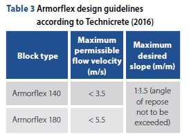
Furthermore, the lack of design guidelines from Armorflex manufacturers is a cause of concern. Technicrete, a South African manufacturer of Armorflex, provides the following design guidelines (Technicrete 2016):
■ Slope limits:
■ Angle of repose of in-situ material should not be exceeded
■ Maximum desired slope = 1V:1.5H
■ Armorflex 140 limiting flow velocity = 3.5 m/s
■ Armorflex 180 limiting flow velocity = 5.5 m/s.
Technicrete (2016) does not specify which slope the maximum desired slope of 1V:1.5H refers to - either longitudinal or side slope. Given the lack of information, there remains a high level of uncertainty in the performance of Armorflex ACBs in channelised applications, especially on channel side slopes.
OBJECTIVES OF THE STUDY
The objectives of the study were to:
■ Provide limiting flow condition parameters for Armorflex 140 and 180 blocks in channelised applications, specifically in terms of Liu's Movability Number.
■ Review the design guidelines of Armorflex manufacturer Technicrete (2016).
■ Compare the findings of the study to the design guidelines for riprap and Reno-mattresses in terms of Movability Number.
STUDY LIMITATIONS
The limitations of the study were the following:
■ The maximum discharge capacity of the hydraulic laboratory was just under 600 l/s, which ruled out the possibility of full-scale (prototype) testing. A scale factor of 1:3 was used.
■ Only applicable to cellular Armorflex blocks, specifically Armorflex 140 and Armorflex 180. The term "cellular" means that the blocks have open cells, compared to solid Armorflex blocks, which do not have open cells.
■ Fully turbulent flow conditions with Reynolds Numbers >3000.
■ Particle Reynolds Numbers (Re*) ranging between 11025 and 131397.
■ Since symmetric flow in the investigated trapezium shape channel was assumed, only half of the canal was investigated in the physical model with an artificial vertical smooth boundary on the canal centre line.
Because of the relative smoothness of the test canal vertical sidewalls of the simulated canal, it was not included in the calculation of the wetted perimeter, and its roughness is therefore ascribed to the much rougher area lined with Armorflex blocks.
■ A bed slope range of 1V:30H (lowest slope) to 1V:10H (steepest slope) and a side slope of 1V:1.5H.
■ Slope correction factors were not applied to the recommended Movability Numbers for Armorflex 140 and 180, as the angle of repose of Armorflex blocks was not determined.
INCIPIENT MOTION THEORY
Given that the aim of the study was to investigate when Armorflex blocks are lifted out of plane under hydraulic flow, an investigation into incipient motion theory was necessary, as incipient motion refers to some threshold of motion. Many renowned researchers in the field of particle movement, such as Armitage (2002), Rooseboom (1992) and Yang (1973), have done studies examining the incipient motion theories most commonly used by design engineers.
Incipient motion is initiated by oscillating eddy currents in the vicinity of the particles (Armitage & McGahey 2003). Eddy currents are complex and close to impossible to be described mathematically. Instead, in an attempt to simplify the theory of incipient motion, researchers made use of a single flow-related parameter in the vicinity of the particle under consideration to define incipient motion. The three most used models of incipient motion, as listed hereunder, were investigated and are discussed in this section:
■ Critical flow velocity approach
■ Shields's critical shear stress approach
■ Liu's stream-power approach.
Critical flow velocity approach
Flow velocity, specifically average flow velocity, is relatively easy to measure. It is therefore no surprise, given the convenience, that many researchers have tried to link incipient motion to some flow velocity (Armitage & McGahey 2003).
The argument for using flow velocity to define incipient motion is that particle movement would commence once the flow velocity in a channel is greater than a specific critical flow velocity (Vcr). However, the problem with this theory is that average flow velocity, although easy to determine, does not represent the velocity in the vicinity of the particle under consideration. On the other hand, local flow velocity, or bed velocity, is extremely difficult, if not impossible, to determine on site (Armitage & McGahey 2003).
Shields' critical shear stress approach
Shields' (1936) widely accepted theory is based on the argument that particle movement would commence once the drag force exerted on the particle exceeds the resistive force. Drag force is influenced by several parameters, including bed shear stress (Raudkivi 1998). The primary criticism against the use of Shields' theory is that particle movement is not uniquely defined by shear stress (Yang 1973). Yang (1973) also argued that at high-particle Reynolds Numbers the vertical lift force cannot simply be ignored from the stability calculations, as Shields only took into account the tangential force. Furthermore, Rooseboom (1992) argued that median particle size is not a sufficient parameter to adequately describe incipient motion and that settling velocity should be used instead.
In deriving his theory, Shields did not take into account that some particles may be more exposed to flow than others, leading to questions being raised by Przedwojski et al (1995), Simons and Sentürk (1992) and Van der Walt (2005).
Liu's stream-power approach
Liu (1957) agreed that local velocity is the energy behind particle movement and that drag force is a function of the particle Reynolds Number (Re*). Liu used stream-power theory to develop a unique relationship between the ratio of shear velocity to the particle settling velocity (V*/Vss) and particle Reynolds Number. Liu (1957) termed the ratio of V*/Vss as the "Movability Number". The resulting curve does not include average or local flow velocity. Particle Reynolds Number is defined by Equation 1:
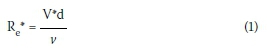
Where:
V* = shear velocity (m/s)
d = particle diameter (m)
v = kinematic viscosity of water = 1.13 X 10⁻⁶ m2/s at 15°C.
Settling velocity Vss is the average velocity achieved by a particle falling alone in quiescent distilled water of infinite extent. Settling velocity is influenced by the particle size, shape, surface roughness, and density, as well as the density and viscosity of the fluid (Armitage & McGahey 2003). Settling velocity is defined by Equation 2 (Raudkivi 1998):
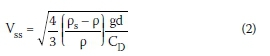
Where:
ps = particle density (kg/m3)
p = fluid density (kg/nï5)
g = gravitational acceleration (m/s2)
CD = drag coefficient.
Shear velocity V* is related to the real fluid velocity that gives rise to a shear stress (Henderson 1966). Many researchers (Armitage 2002; CIRIA, CUR & CETMEF 2007; Simons & Sentürk 1976) have expressed V* as follows:
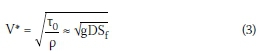
Where:
T0= bed shear stress (Pa)
Sf = energy slope (m/m)
D = flow depth (m).
Many researchers have proposed Movability Numbers for laminar and turbulent flow conditions, as presented in Table 1 on page 16. The analytical solutions in Table 1 are presented graphically in Figure 1. The graph is easy to understand in that, if it plots above a specific Movability Number, movement will commence.
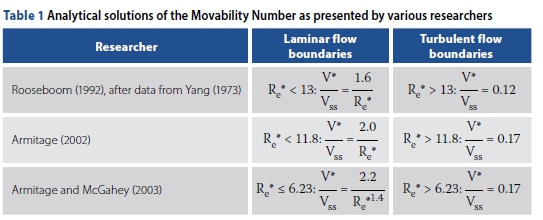
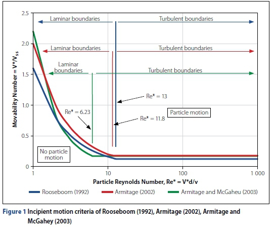
For turbulent flow conditions, in the vicinity of the particle, particle settling velocity is constant. By assuming that the flow is uniform and homogeneous, many researchers showed that the Movability Number plots along a horizontal line for a certain flow condition and particle size (Langmaak 2013), as shown in Figure 1.
Even though Shields and Liu assume uniform flow, researchers such as Yang (1973), Rooseboom (1992), Przedwojski et al (1995), Stoffberg (2005) and Langmaak (2013) support Liu's (1957) stream-power model for providing the soundest theoretical base of incipient motion theory for non-cohesive particles in natural rivers.
For prefabricated paving blocks the South African National Roads Agency Limited (SANRAL 2013) recommends a Movability Number of 0.12 at particle Reynolds Numbers larger than 13.
ARMORFLEX ARTICULATING CONCRETE BLOCKS
Background and physical characteristics
Armorflex blocks are machine-compressed concrete blocks of uniform size, shape and weight (Armortec Incorporated 1981). Armorflex aims to combine the favourable aspects of a flexible lining (such as porosity, vegetation and habitat enhancement, and ease of installation) with the high-force resistance of rigid linings. Armorflex mats are free to conform to the contours of the subgrade, even if settlement were to occur after installation (Schweiger & Holderbaum 2001). However, like many other revetments, Armorflex is not intended for slope stabilisation.
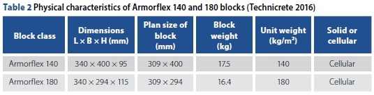
When licensed internationally, it was done so in the form of two cellular Armorflex types: Armorflex 140 and Armorflex 180, with the number referring to the weight of a packed block matrix per square metre (kg/m2). Table 2 presents the physical characteristics of Armorflex 140 and 180.
Armorflex blocks have holes on either side of the open cells to allow blocks to be linked longitudinally with either galvanised wire cables or polyester ropes. Even though the National Concrete Masonry Association (NCMA 2010) argues that cables do not increase the hydraulic stability of an Armorflex revetment system, it aids in making installation less labour-intensive and makes the use of soil anchors more effective (Schweiger & Holderbaum 2001). The City of Tshwane (2018) recommends that, for long-length cabled Armorflex installations, anchor beams are cast every 50 m (unless otherwise specified by the engineer) to prevent failure of the entire structure. The City or Tshwane (2018) also specifies intermediate anchoring in the form of Y-fencing bars driven into the ground at 2 m spacing through the block openings before encasing it with concrete.
Armorflex blocks are typically installed on a filter layer. Geotextile filters may be used as a simplified alternative to a graded filter, although not all roots may be able to penetrate the geotextile, constricting the establishment of vegetation (Technicrete 2016). The filter layer should be designed to permit seepage to occur freely, as well as to prevent fines from washing out from underneath the blocks, which could potentially cause the undermining of the revetment.
Manufacturer design guidelines
Armorflex manufacturers present design guidelines either in terms of limiting flow conditions or by means of moment stability analyses, i.e. factor of safety (FoS) methods. Limiting flow characteristics may include parameters such as flow velocity, bed shear stress, flow depth, Froude Number, and Movability Number, even though no manufacturers use Froude Number or Movability Number as a limiting condition. Factor of safety methods include the determination of overturning moments and resisting (stabilising) moments about a single block. For this study, Technicrete's (2016) design guidelines were of interest.
Technicrete's (2016) Armorflex product brochure specifies a critical flow velocity and a maximum desired slope as the hydraulic limitations for Armorflex 140 and 180 blocks, as presented in Table 3. Technicrete (2016) also mentions that the angle of repose of the embankment material should never be exceeded.
PHYSICAL MODEL STUDY
The hydraulic laboratory of Stellenbosch University had a discharge capacity of just under 600 l/s, which was not enough to initiate failure of full-scale prototype Armorflex blocks. An undistorted physical model study was therefore undertaken to determine the incipient motion conditions of Armorflex 140 and 180 blocks on steep slopes. A half-width canal cross-section was used, assuming symmetry with the aim to decrease the effects of scaling.
Prototype-to-model scaling and scale effects
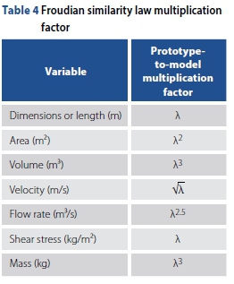
Hydraulic model studies aim to simulate the direct physical conditions in the same medium as in the prototype. In free-surface-flow conditions, inertial and gravitational forces govern the flow. Therefore, the Froudian similarity law (i.e. Froude Number remains constant) was used to convert model values into scale prototype values. Table 4 shows the model-to-prototype scaling rations used. The selected scale for this model study was 1:3 (i.e. X = 3).
According to Novak et al (2014), the main scale effects in model studies are model roughness and the model approach conditions associated with turbulent boundary layer development, cavitation effects, surface tension effects and aeration formation and vortex formation problems. However, some of these effects can be minimised with a high enough Reynolds Number. According to Novak et al (2014), open channel flow models require Reynolds Numbers above 103.5 - 104.5 to avoid scale effects. In addition, Novak et al (2014) recommends a minimum flow depth of 0.03 m to avoid surface tension effects. All results were deemed representative of the prototype based on the scale effects criteria of Novak et al (2014).
Manufacturing of Armorflex model blocks
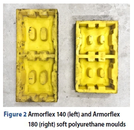
As volume is the most important parameter that controls, with the mass density, the mass of the unit and in effect its stability, high-quality moulds were manufactured to ensure precise and consistent block dimensions and shape. Figure 2 shows the manufactured moulds of the Armorflex 140 and 180 model blocks.
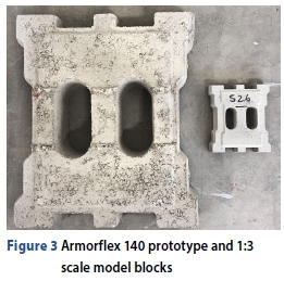
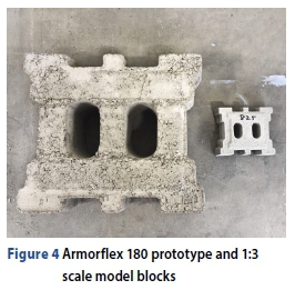
The model blocks were manufactured using a high-strength mortar mix design of sand, cement, water and a viscosity modifying agent (Chryso Aquaberton). Figures 3 and 4 show plan views of the prototype and model scale Armorflex 140 and 180 blocks, respectively. The model blocks were manufactured without holes for cables/wires, as it proved impractical at the selected scale. Furthermore, some researchers (Clopper 1989; NCMA 2010) disregard the effect of cables on system stability, while others (Escarameia 1995; 1998) show a difference in performance between cabled and loose concrete block revetments. As a result, the effect of cables on the stability of ACB revetments remains uncertain.
Experimental work
Weight and density of Armorflex
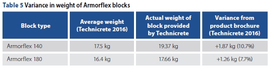
According to Technicrete (2016) the average prototype Armorflex 140 and 180 block weighs 17.5 kg and 16.4 kg, respectively. However, the weight of the sample blocks provided by Technicrete for the study differed from the average weights stated in their product brochure. Table 5 shows the discrepancy in weight, proposing that a big tolerance may exist in terms of block volume, unit weight and possibly concrete density in the manufacturing process of Armorflex blocks.
Another manufacturer of Armorflex 180 in South Africa, INCA Concrete Products (2018), states that the dry mass average of six samples should not be less than 16.4 kg, with no block weighing less than 15.25 kg (INCA Concrete Products 2018). A lower weight limit variance of ±7% was thus adopted. The manufacturer provides no upper weight limit.
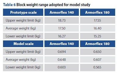
To set up an allowable weight range for the scaled blocks used in this model study, a 7% variance from the average weight stated by Technicrete (2016) was adopted. Table 6 presents the block weight envelope for both prototype and model scale Armorflex blocks. Each block was numbered before being weighed, using a calibrated digital scale (Digi DS-788 with a 6/15 kg capacity and a scale interval of 2/5 g). Blocks weighing outside the unit weight envelope of Table 6 were rejected and discarded.
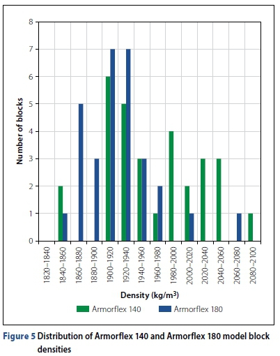
The density of the Armorflex 140 and 180 model blocks was determined using the mass and a simple water displacement test to determine volume on a sample of 30 randomly selected blocks of each type.
Figure 5 shows the distribution plot for the densities of the model Armorflex 140 and 180 blocks. Average concrete densities of 1921.9 kg/m3 and 1920.8 kg/m3 were determined for the samples of Armorflex 140 and 180 blocks, respectively. The variance in block volume was ascribed to human error during the filling of the moulds. An average concrete density of 1 921.4 kg/m5 was therefore adopted and used in all calculations. For concrete, this density is strikingly low. INCA Concrete Products (2018) claim that Armorflex blocks are manufactured using concrete with density no less than 2 100 kg/m3. The difference could be ascribed to a possible safety factor incorporated by the manufacturers of Armorflex to ensure that the minimum unit weight criteria are always comfortably met.
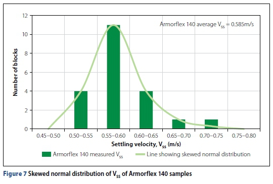
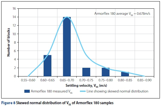
Settling velocity of Armorflex
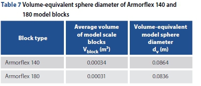
Incipient motion studies require the accurate determination of the settling velocity. Equation 2 calls for a particle size d, which generally refers to a specific sieve size. Due to the shape of an Armorflex block, however, a representative sphere diameter was determined instead. In order to remain impartial to particle orientation during free-fall conditions, a volume-equivalent sphere diameter was determined using Equation 4 (Pabst & Gregorova 2007). Table 7 presents the calculated values.
Where:
dv = volume-equivalent sphere diameter (m)
Vblock= volume of Armorflex block (m3)
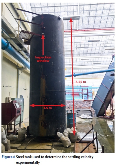
The settling velocity of the blocks was determined experimentally in a 5.55 m high steel tank in the hydraulic laboratory of the Stellenbosch University. Figure 6 shows the steel tank with its dimensions. The steel tank was filled with water up to its brim. Blocks were released from a stationary position and the time that the blocks took to fall to the bottom was recorded. A sample size of 30 blocks of each type was tested. The initial acceleration of the blocks (from rest to terminal velocity), after being released, was taken into account. Respective average settling velocities of 0.585 m/s and 0.678 m/s were calculated for Armorflex 140 and 180 model blocks. Figures 7 and 8 present the distribution of the viable settling velocity test results.
Drag coefficient of Armorflex
With dv and Vss known, the drag coefficient could be determined by solving Equation 2. Average drag coefficient values of 3.045 and 2.191 were determined for Armorflex 140 and 180, respectively.
Definition of incipient motion for model study
For the model study it was important to define what constitutes as block failure. Incipient motion was defined as the loss of solid contact between one or more blocks and the foundation bed, i.e. the point at which one or more blocks are lifted out of plane. This definition is in accordance with the ASTM's (2008a) first condition of what can be used as guidance for blocks reaching their stability threshold. As the foundation bed was rigid and non-erodible, the loss of soil beneath the filter layer and the mass slumping/sliding of the foundation were not possible, i.e. block failure due to bed failure was impossible.
Hydraulic tests
Test scenarios investigated
Tests were conducted on three different bed slopes (1:30, 1:20 and 1:10), after which a side slope of 1V:1.5H was added to each bed slope. This side slope was selected as it is the maximum desired slope recommended by Technicrete (2016). Given that two types of Armorflex blocks were investigated, 12 different test canal setups were constructed. These 12 canal setups could be classified into four test scenarios:
■ Armorflex 140 on bed slopes
■ Armorflex 140 on side slopes
■ Armorflex 180 on bed slopes
■ Armorflex 180 on side slopes.
Each test canal setup was referenced using a three-part code, with the first part referring to canal bed slope, the second to canal side slope and the third to the block type. Table 8 lists the 12 test canal setups investigated.
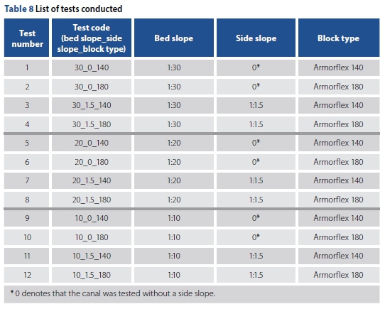
Each test was repeated at least twice to investigate the repeatability of the results obtained. In total, 39 tests were conducted, of which 24 rendered viable results for data analyses.
Test canal layout and construction
The rectangular canal used for the model study was constructed with brick walls, 23 m long (measured from inlet pipe to the end of canal), 1.2 m deep and 0.935 m wide. Figure 9 schematically shows the test canal layout of the hydraulic laboratory model. Water was pumped through a 600 mm ND mild steel pipeline, through the calibrated flow meter and into the stilling basin at the upstream end of the test canal. An in-line gate vale controlled the discharge into the stilling basin. Downstream of the stilling basin, stacked hollow bricks straightened the flow and prevented waves from entering the approach canal, forcing the flow to be uniform. Flow would then overtop a weir at chainage 0 (CH 0) and enter the 6 m long test section starting at CH 3. On the downstream end the water flowed freely into the downstream catchpit, without controlling tailwater depths.
Flow was measured using an electromagnetic Flowmetrix Safmag flow meter that was installed into the 600 mm nominal diameter ND inlet pipeline. The flow meter accurately measured flow rates with an approximate error of 0.0005 m3/s. Typical cross-sections of the constructed canals for the bed slope tests and side slope tests are shown in Figures 10 and 11, respectively.
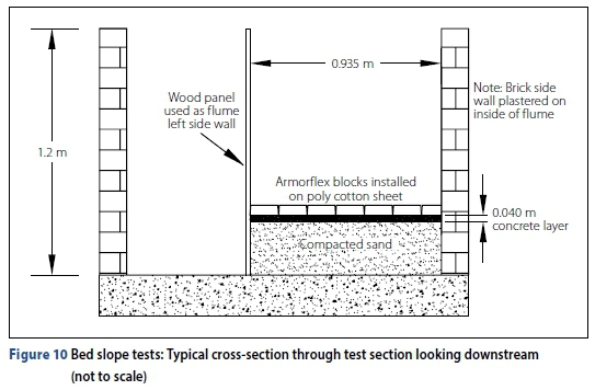
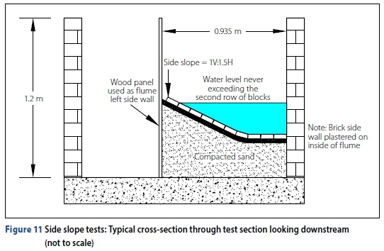
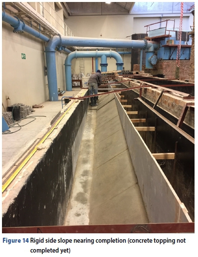
Blocks were tested on rigid embankments which were formed using a 40 mm cement plaster layer. The rigid bed eliminated the possibility of the foundation eroding, resulting in block failure. It was deemed fair to assume that results obtained from a rigid bed study would be similar to those obtained from tests on stable erodible beds. A smooth transition of flow into the test section was promoted by "sinking" the test section into the bed. Figure 9 shows this step on the upstream and downstream ends of the test section.
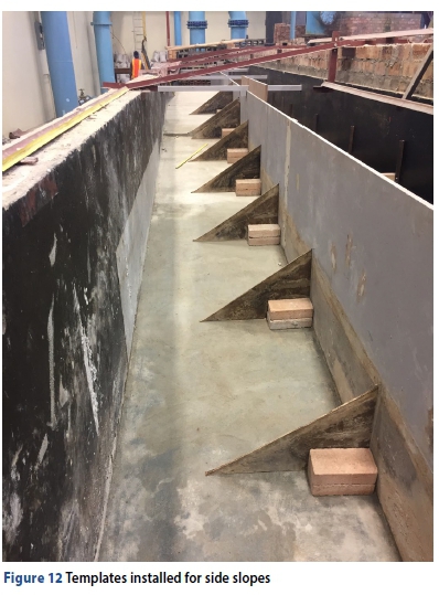
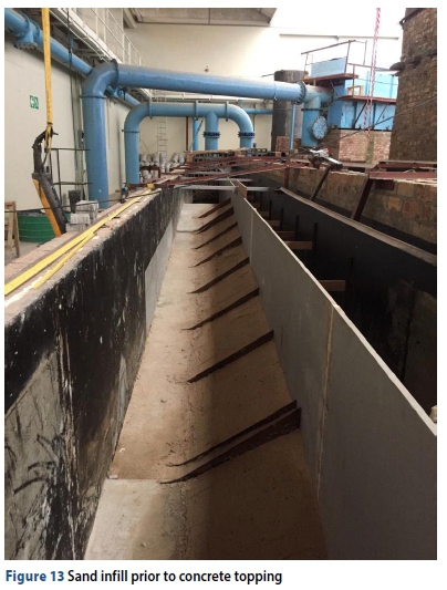
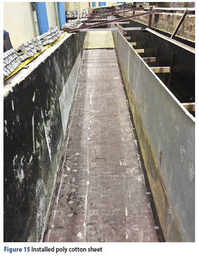
The side slopes of the half-trapezoidal canals were set out using 6.4 mm thick masonite templates, installed at 1 m spacing and levelled using a dumpy level. Figures 12 to 15 show how the canals were constructed, prior to block installation. A permeable poly cotton sheet was installed along the length of the test section to represent a scaled geotextile filter layer.
Installation of Armorflex block units
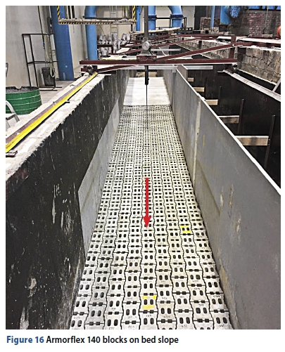
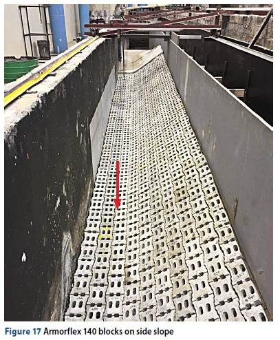
Armorflex model blocks were installed according to the guidelines of Armortec (2016), from the downstream end proceeding in an upstream direction. As the blocks were not linked with cables, blocks were hand-packed. Figures 16 and 17 show Armorflex 140 blocks installed for a bed slope and side slope test, respectively. Flow direction is indicated by a red arrow.
The column of blocks against the symmetry wall (brick wall in Figure 16) had to be cut to fit into the test canal. SikaFlex was used to glue the cut blocks to the canal side and underlying cotton sheet to prevent failure. Additionally, the first three rows of blocks at the upstream end and last three rows at the downstream end of the test section were also glued to the floor, preventing failure to occur in these areas. Furthermore, in the side slope tests, the blocks installed on the bed had to be fixed to the floor, as they proved to be less stable than those installed on the side slope.
Methodology followed
After installation, the structure was visually inspected for blocks protruding more than the allowed maximum of 3.3 mm (10 mm full scale) as recommended by The City of Tshwane (2018). The structure was also inspected for blocks not tightly packed or with no contact with adjacent blocks. The test section was surveyed using a dumpy level, with bed levels (i.e. the top of block levels) recorded at 500 mm intervals along the centre line of the test section.
At the start of each test, a small flow, typically in the range of 30-50 l/s, was released over the revetment to identify any protruding blocks. Protruding blocks would typically result in local turbulence in the area. In such a case the cause of the protrusion would be investigated and rectified. The flow was slowly increased at a rate of ±10 l/s every five minutes, with water surface elevation measurements recorded at each goal discharge, until failure was observed. The test would then be repeated to investigate the repeatability of results. As the test canal walls were non-transpar ent, blocks could only be monitored for movement from the top.
Block movement would not always result in catastrophic failure only. There were cases where blocks were lifted out of plane without completely dislodging from the structure. At greater flow depths, however, the visual monitoring of blocks for slight movement was challenging and, in most cases, only catastrophic failure of the revetment could be recorded as the point of incipient motion.
Data collection
The data collected during the hydraulic tests included embankment elevations, water-surface elevations (WSEs), the position of block failure and the flow rate at incipient motion. Flow rate was read from the laboratory's calibrated flow meter. Embankment and water surface elevations were measured at 500 mm intervals along the canal centre line using a needle gauge attached to a trolley moving on a rail along the length of the canal. Only the WSE readings upstream of the point of block failure could be used in the analysis of the collected data because of the sudden increased turbulence and change in flow conditions downstream of the point of block failure.
The high turbulence of flow in the test canal made WSE readings challenging to capture accurately. To correct possible errors made during the recording of the WSEs, a linear trendline of the observed WSE data points was plotted, effectively obtaining a representative WSE at each measurement station upstream of the point of failure.
The laboratory refilled the tanks with clean water only after Tests 1 and 2 had already been completed. Upon removing the blocks from the canal after Tests 1 and 2 it was noticed that sand particles from the dirty water had been washed in between the blocks, reinforcing the system by increasing the friction between adjacent blocks. This resulted in postponed block failure in Test 1 and no failure in Test 2. The results presented in the next section clearly show the abnormal stability of the Armorflex systems tested in Tests 1 and 2. The results were, however, still included in the analysis, but were disregarded in defining the critical flow conditions at incipient motion.
DATA ANALYSIS
Typical flow parameters at failure
Collected data from the laboratory tests was analysed to determine typical flow parameters such as hydraulic radius (R), cross-sectional average flow velocity (V), Froude Number (Fr), energy grade line (EGL) elevation and shear stress (t) at each measurement station upstream of the point of block failure. The analysis also included the determination of the optimal Manning's n value that best represents the observed data of each test. As the main aim of this study was to develop design guidelines in terms of Liu's Movability Number, the parameters required to plot the results on Liu's Diagram were determined.
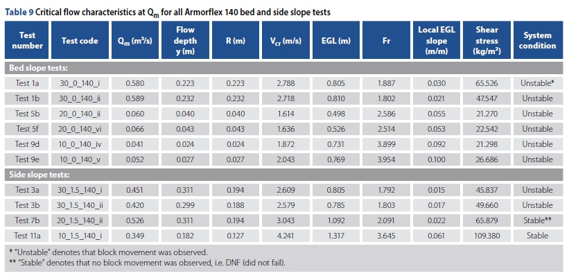
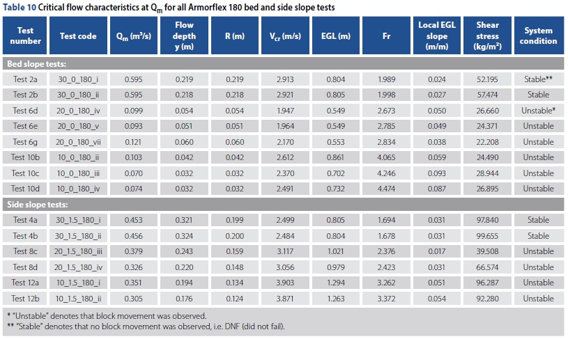
Tables 9 and 10 present the critical station in each of the tests conducted on Armorflex 140 and Armorflex 180, respectively. The flow at which block movement was observed is referred to as Qm. The flow conditions at the measurement station just upstream of the point of block failure were assumed to represent the critical flow conditions resulting in failure. Where no failure was observed, the station with the highest Movability Number was taken as the most critical station not resulting in failure. As mentioned under study limitations, the side walls were not considered in the calculation of the wetted perimeter. Therefore, R = y for all bed slope tests.
Observed Manning's n value
The optimal Manning's n value that best represents the data observed in each test was determined using the method presented by ASTM (2008b). The average optimal Manning's n values minimising the objective functions in all Armorflex 140 and 180 test scenarios are presented in Table 11. Technicrete (2016) presents a typical Manning's n value range of 0.025 - 0.035 for Armorflex blocks.
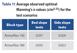
The difference between Technicrete's specified roughness values and those obtained in this study could be attributed to differences in how the blocks were manufactured. Prototype Armorflex blocks are typically dry-packed and hydraulically compressed in the mould, whereas the model blocks were wet-cast into soft polyurethane moulds. The surface finish on the wet-cast concrete blocks was smooth and even, while that of the dry-packed prototype blocks is more textured, resembling the surface finish of a paving brick. Reference is made to Figures 3 and 4 that show the difference in surface finish between the prototype and model Armorflex blocks. Another possible cause of the low Manning's n values is that the tests were conducted under controlled laboratory conditions, meaning no debris or foreign material could influence the roughness parameter, whereas field measurements might be affected in such a way.
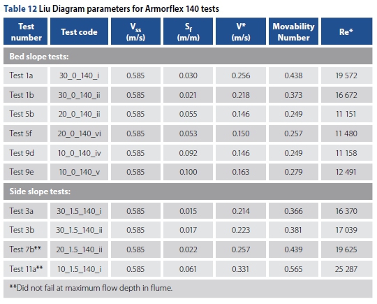
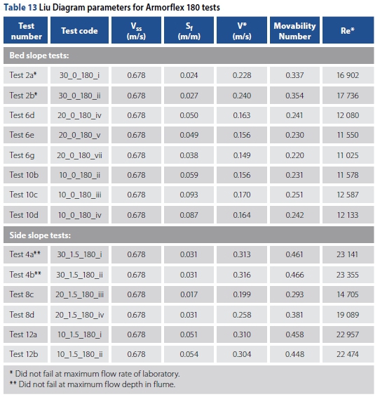
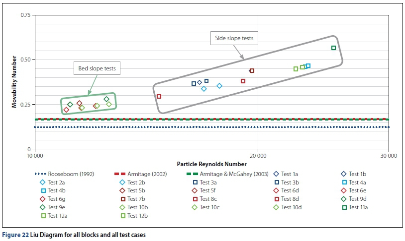
Liu Diagram parameters and plots
Liu's Diagram plots the Movability Number (V*/Vss) against the particle Reynolds Number. With settling velocity determined experimentally, shear velocity and particle Reynolds Number could be determined using the laboratory data. Even though Liu assumes uniform flow conditions (So = Sf ), Sf was calculated as the local EGL slope at the measurement station just upstream of the point of failure. With Sf determined, shear velocity and particle Reynolds Number could be calculated using Equations 3 and 1, respectively. The kinematic viscosity of water was taken as 1.13 X 10⁻⁶ m2/s in the calculation of the particle Reynolds Number, even though no water temperature measurements were taken in the laboratory. Tables 12 and 13 present the processed data required to plot the test results on the Liu Diagram for Armorflex 140 and Armorflex 180, respectively.
The results of each of the four test scenarios were plotted on the Liu Diagram, as presented in Figures 18 to 21. Figure 22 presents the plot for all blocks and all cases on one graph. Figure 22 illustrates that the side slope test results plotted higher on the Liu Diagram than bed slope test results.
This verifies the observation that blocks installed on bed slopes are less stable than blocks installed on the 1H:1.5H side slope.
All test scenarios show a trend of increasing the Movability Number with an increasing particle Reynolds Number. SANRAL (2013) equates the Movability Number of loose articulating concrete blocks (such as Armorflex) to 0.12, for particle Reynolds Numbers larger than 13. The results obtained from this study show that SANRAL's (2013) Movability Number is indeed conservative for design purposes.
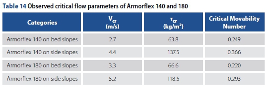
Table 14 shows the critical flow velocity, shear stress and Movability Numbers for the four test scenarios investigated, with the Movability Number being recommended for use in defining the point of incipient motion. For each test scenario, a 100% exceedance value was assumed, meaning that the lowest obtained Movability Number was taken as the critical value. No safety factors were applied to the values presented in Table 14.
EVALUATION OF TECHNICRETE'S (2016) DESIGN GUIDELINES
Figure 23 presents the critical flow velocities for each test scenario investigated, compared to the limiting flow velocities specified by Technicrete (2016). The graph shows that Technicrete's limiting flow velocity of 3.5 m/s for Armorflex 140 blocks may be an overestimation for blocks installed on bed slopes, while the critical velocity achieved on side slopes was greater than the 3.5 m/s limiting flow velocity. Armorflex 180's bed and side slope tests resulted in suggested critical flow velocities lower than Technicrete's limiting flow velocity of 5.5 m/s. However, incipient motion theory clearly argues against the use of flow velocity as a parameter to define incipient motion conditions of non-cohesive particles.
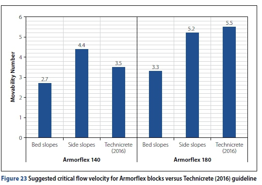
Technicrete's (2016) design guidelines are therefore not suitable for design.
COMPARISON TO INCIPIENT MOTION CRITERIA OF RIPRAP AND RENO-MATTRESSES
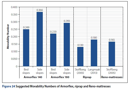
The incipient motion criteria for riprap and Reno-mattresses have been thoroughly investigated by many researchers, being mainly presented in terms of critical flow velocity and shear stress. Stoffberg (2005) and Langmaak (2013) managed to apply the stream-power-based incipient motion studies of Rooseboom (1992) and Armitage (2002) to define incipient motion conditions for riprap and Reno-mattresses in terms of Liu's Movability Number.
Stoffberg (2005), basing his findings on tests conducted by Simons et al (1984), suggested Movability Numbers of 0.13 and 0.165 for riprap and Reno-mattresses, respectively. Langmaak (2013), however, found that a critical Movability Number of 0.18 can be used for riprap on extremely steep bed slopes under non-uniform flow conditions, which is close to the 0.17 recommended by Armitage (2002).
Figure 24 shows that the suggested Movability Numbers of Armorflex 140 and 180 blocks are greater than those suggested for riprap and Reno-mattresses, as proposed by Stoffberg (2005) and Langmaak (2013). Unlike riprap and Reno-mattresses, Armorflex has no material smaller than the design weight that can be dislodged by the forces of flowing water, subsequently undermining the larger material (Armortec Incorporated 1981).
CONCLUSIONS
The study showed that Liu's Movability Number can be used to define the critical point of incipient motion for Armorflex blocks. The Movability Numbers recommended for design of Armorflex 140 installed on bed and side slopes are 0.249 and 0.366, respectively, while those for Armorflex 180 are 0.220 and 0.293, respectively. In a wide trapezoidal channel, Armorflex blocks installed on a side slope of 1V:1.5H are more stable than blocks installed on a bed slope. Dimensionless stability factors of 1.47 and 1.33 can respectively be applied to the Movability Numbers of Armorflex 140 and 180 blocks installed on bed slopes to determine the Movability Numbers of the blocks on side slopes. Blocks installed on channel side slopes experience smaller local flow velocities than blocks on the bed. Furthermore, the additional load from blocks resting on top of each other on a side slope could possibly have a stabilising effect.
The model study showed increased system vulnerability once a block was dislodged from the structure. Consideration should be given to intermittent concrete beams across a channel at appropriate intervals to prevent failure of an entire Armorflex structure.
All recommended Movability Numbers for Armorflex are greater than SANRAL's (2013) proposed Movability Number of 0.12 (for natural sediments like sand, gravel, boulders and rocks), rendering SANRAL's (2013) criteria conservative for design. The recommended Movability Numbers are also greater than those recommended for riprap and Reno-mattresses. Unless site conditions fall outside the limitations of this study, no safety factor needs to be applied to the recommended Movability Numbers. Recommended Movability Numbers represent the beginning of movement. Selected design Movability Numbers smaller than the recommended Movability Numbers constitute a safe design.
The respective critical flow velocities of 2.7 m/s and 3.3 m/s obtained in this study for Armorflex 140 and Armorflex 180 on bed slopes propose that Technicrete's (2016) respective limiting flow velocities of 3.5 m/s and 5.5 m/s are overestimations. However, according to incipient motion theory, average flow velocity is not a suitable parameter for defining incipient motion conditions. Therefore, Technicrete's (2016) design guidelines alone are not suitable for the safe and stable design of Armorflex-lined structures.
RECOMMENDATIONS FOR FUTURE STUDIES
This study investigated the hydraulic performance of Armorflex blocks in super-critical flow conditions (Fr > 1), which is typically the flow regime concrete-lined canals are designed for to limit costs. A study is required to determine the incipient motion conditions of Armorflex in sub-critical flow conditions (Fr < 1).
For this study, hydraulic testing was conducted on loose Armorflex concrete blocks.
Even though the NCAMA (2010) argues that cables do not increase the hydraulic stability, it is recommended that this research be extended with follow-up research to include interlocking cables/wires to test the impact thereof and how the results differ.
Given that this study investigated the stability of Armorflex blocks in a straight channel only, further research is recommended whereby sharp bends in the horizontal alignment of ACB channels are considered.
As settling velocity is a critical parameter in any Movability Number analysis, the accurate determination thereof is crucial. It may be an interesting experiment to determine the settling velocity of prototype Armorflex blocks and to compare the findings with the settling velocities determined in this study.
The Movability Numbers presented were not adjusted with slope correction factors. To consider the effect of the respective slopes on incipient motion conditions, the angle of repose of Armorflex blocks is required. It is recommended that future incipient motion studies determine the angle of repose of Armorflex.
The results from this study showed that blocks installed on a side slope of 1V:1.5H are more stable than blocks installed on a bed slope ranging between 1V:30H and 1V:10H. An investigation is required to determine the optimum side slope of Armorflex blocks in channelised applications.
REFERENCES
Armitage, N P 2002. A unit stream power model for the prediction of local scour. PhD Thesis. University of Stellenbosch. [ Links ]
Armitage, N & McGahey, C 2003. A unit stream power model for the prediction of local scour in rivers. WRC Report 1098/1. Pretoria: Water Research Commission, p 3. [ Links ]
Armortec 2016. Armorflex installation guide. https://www.conteches.com/technical-guides/search?filter=PNNA22FI91. [ Links ]
Armortec Incorporated 1981. Armorflex erosion control system: Bank and channel protection. Technical Bulletin BC-1. Georgia: Armortec. [ Links ]
ASTM 2008a. ASTM D7277-08. Standard Test Method for Performance Testing of Articulating Concrete Block (ACB) Revetment Systems for Hydraulic Stability in Open Channel Flow. West Conshohocken, PA: ASTM International. [ Links ]
ASTM 2008b. ASTM D7276-08. Standard Guide for Analysis and Interpretation of Test Data for Articulating Concrete Block (ACB) Revetment Systems in Open Channel Flow. West Conshohocken, PA: ASTM International. [ Links ]
CIRIA, CUR & CETMEF 2007. The Rock Manual. The Use of Rock in Hydraulic Engineering, 2nd ed. Report C683. London: CIRIA. [ Links ]
City of Tshwane 2018. Armorflex typical standard details. http://www.tshwane.gov.za/sites/residents/Services/Documents/STD012_sh1of1.pdf. [ Links ]
Clopper, P E 1989. Hydraulic stability of articulating concrete block revetment systems during overtopping flow. Report No. FHWA-RD-89-199. Washington, DC: Federal Highway Administration. [ Links ]
Escarameia, M 1995. Channel protection: Gabion mattresses and concrete blocks. Report SR 427. Wallingford, UK: HR Wallingford. [ Links ]
Escarameia, M 1998. River and Channel Revetments: A Design Manual. London: Thomas Telford. [ Links ]
Henderson, F M 1966. Open Channel Flow. New York: Macmillan. [ Links ]
INCA Concrete Products 2018. Armorflex Brochure. https://www.specifile.co.za/wp-content/uploads/2017/10/inca-armorflex-2017-08-pdf.pdf. [ Links ]
Langmaak, K R 2013. Incipient motion of riprap on steep slopes. MEng Dissertation. University of Stellenbosch. [ Links ]
Leidersdorf, C B, Gadd, P E & McDougal, W G 1988. Articulated concrete mat slope protection. Proceedings, 21st International Conference on Coastal Engineering, 20-25 June 1988, Costa del Sol, Malaga, Spain, pp 2400-2415. [ Links ]
Liu, H K 1957. Mechanics of sediment-ripple formation. Journal of the Hydraulics Division, ASCE, 83(2): 1-23. [ Links ]
NCMA (National Concrete Masonry Association) 2010. Design Manual for Articulating Concrete Block (ACB) Revetment Systems.2nd ed. Herndon, VA: NCMA Publications. [ Links ]
Novak, P, Moffat, A I B, Nalluri, C & Narayanan, R 2014. Hydraulic Structures. Boca Raton, FL: CRC Press. [ Links ]
Pabst, W & Gregorová, E 2007. Characterization of particles and particle systems. Proceedings, ICT Conference, Prague. [ Links ]
Przedwojski, B, Btazejewski, R & Pilarczyk, K W 1995. River Training Techniques: Fundamentals, Design and Applications. Rotterdam: AA Balkema. [ Links ]
Raudkivi, A J 1998. Loose Boundary Hydraulics. Rotterdam: AA Balkema. [ Links ]
Rooseboom, A 1992. Sediment transport in rivers and reservoirs: A southern African perspective. WRC Report No. 297/1/92. Stellenbosch: Sigma Beta. [ Links ]
SANRAL (South African National Roads Agency Limited) 2013. Surface drainage. Chapter 5. In Drainage Manual, 6th ed. Pretoria: SANRAL. [ Links ]
Schweiger, P G & Holderbaum, R E 2001. The ABC's of ACB's: An assessment of articulating concrete blocks for embankment overtopping protection. MEng Dissertation. Uiversity of Stellenbosch. [ Links ]
Shields, A 1936. Application of similarity principles and turbulence research to bed-load movement. Pasadena, CA: California Institute of Technology. [ Links ]
Simons, D B & Sentürk, F 1976. Sediment transport technology. Fort Collins, CO: Water Resources Publications. [ Links ]
Simons, D B & Sentürk, F 1992. Sediment transport technology: Water and sediment dynamics. Littleton, CO: Water Resources Publications. [ Links ]
Simons, D B, Chen, Y H & Swenson, L J 1984. Hydraulic test to develop design criteria for the use of Reno Mattresses. Fort Collins, CO: Colorado State University, Civil Engineering Department. [ Links ]
Stoffberg, F 2005. Evaluation of the incipient motion criteria for rock in Reno Mattresses and rip rap. MSc Dissertation. University of Stellenbosch. [ Links ]
Technicrete 2016. Armorflex Brochure. http://www.technicrete.co.za/product-category/erosion-protection. [ Links ]
Van der Walt, S C 2005. Mathematical modelling of sediment transport dynamics in the Berg River considering current and future water resources. MEng Dissertation. University of Stellenbosch. [ Links ]
Yang, C T 1973. Incipient motion and sediment transport. Journal of the Hydraulics Division, ASCE, 99(10): 1679-1704. [ Links ]
 Correspondence:
K Delport
AECOM SA, Waterside Place, South Gate, Tyger Waterfront
Carl Cronje Drive, Bellville 7530, South Africa
T: +2 7 74 1 01 4 877; E: kobus.delport@aecom.com
G R Basson
Water Division (Hydraulics), Department of Civil Engineering, Stellenbosch University
Private Bag X1, Matieland 7602, South Africa
T: +27 82 920 6511; E: grbasson@sun.ac.za
A Bosman
Water Division (Hydraulics), Department of Civil Engineering, Stellenbosch University
Private Bag X1, Matieland 7602, South Africa
T: +27 82 200 9353; E: abosman2@sun.ac.za

KOBUS DELPORT (AMSAICE) is a Civil Engineer in the Floods and Stormwater Department at AECOM. He has over seven years of experience mainly in flood hydrology assessments, the design of stormwater and hydraulic structures and hydraulic modelling. He obtained his Masters {cumlaude) in Hydraulic Engineering from Stellenbosch University in 2019.

PROF GERRIT BASSON (Pr Eng, FSAAE, MSAICE) is professor in Hydraulic Engineering in the Civil Engineering Department at Stellenbosch University. He obtained his PhD from Stellenbosch University in 1996 and has 35 years' experience mainly in the fields of river hydraulics, sedimentation management and the design of large hydraulic structures. He has worked on projects in 21 countries and is an Honorary Vice-President of ICOLD (International Commission on Large Dams).

DR ADELE BOSMAN (Pr Eng) Is a lecturer In Hydraulic Engineering in the Civil Engineering Department at Stellenbosch University. She has more than 12 years' experience mainly in stormwater, river hydraulics, rock scour and the design of large hydraulic structures. She obtained her PhD from Stellenbosch University In 2021.

