


Services on Demand
Article
 English (pdf)
 Article in xml format
 Article references
Indicators

Related links
-
 Cited by Google
 -
 Similars in Google
Share

 Permalink
Journal of the South African Institution of Civil Engineering
On-line version ISSN 2309-8775
Print version ISSN 1021-2019
J. S. Afr. Inst. Civ. Eng. vol.63 n.1 Midrand Mar. 2021
http://dx.doi.org/10.17159/2309-8775/2021/v63n1a5
TECHNICAL PAPER
Review of compatibility between SANS 10400 deemed-to-satisfy masonry wall provisions and loading code
W I de Villiers; G P A G van Zijl; W P Boshoff
ABSTRACT
South Africa has a housing shortage estimated in excess of 2 million units. This backlog is being addressed predominantly with the construction of 40 m2 low-income, single-storey, detached, state-subsidised houses built with conventional concrete masonry units, regulated by the Application of the National Building Regulations, SANS 10400. However, several developments warrant a reconsideration of SANS 10400 deemed-to-satisfy masonry wall provisions. Two critical configurations of single-storey, unreinforced, bonded masonry walls are generated, based on these deemed-to-satisfy provisions. Subsequently, a simplified micro-scale finite element model is used to analyse these configurations under serviceability and ultimate limit state loading conditions. Characterisation tests of the concrete masonry material, together with numerical fitting to test data and data taken from literature, generate the necessary parametric input. The numerical analyses reveal that in half of the load cases, the walls' resistances failed to achieve the design load as required by the South African loading code. A significant shortfall was found for the out-of-plane resistance against the wind load, as well as structural vulnerability under seismic loading due to the geometric layout permitted by the deemed-to-satisfy rules. This indicates that the SANS 10400 provisions for masonry wall panel geometries require reconsideration, especially given the recent revision of the South African loading code.
Keywords: low-income housing, National Building Regulations, SANS 10400, South African loading code, concrete masonry, simplified micro-model
INTRODUCTION
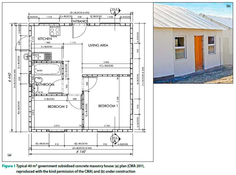
The South African government has provided nearly 3 million subsidised housing units since 1994 (Department of Human Settlements 2017). However, a backlog of over 2 million units persists (Sisulu 2016). Government-subsidised housing units are typically a stand-alone dwelling of 40 m2 (Laubscher 2014), containing a kitchen, living area, two bedrooms and a bathroom (see Figure 1).
The structural design of housing in South Africa is regulated by the Application of the National Building Regulations, based on the National Building Regulations and Standards Act of 1977 (RSA 1977). The standard was first published in 1985 but has since been updated several times to the current edition SANS 10400 (SANS 2010a). On a practical level, all housing construction in South Africa is regulated by the National Home Builders Registration Council (NHBRC), the establishment of which is enshrined in The Housing Consumers Protection Measures Act (RSA 1995; NHBRC 2015).
The NHBRC stipulates general home building technical requirements and guidelines in the form of the Home Building Manual and Guide, which is based on SANS 10400.
Both SANS 10400 and the Home Building Manual rely on normative reference standards for the material-specific design aspects, which have typically been prescriptive in nature. For masonry, this reference standard is SANS 10164 The structural use of masonry (prescriptive-based), as well as the recently adopted SANS 51996 Design of masonry structures (performance-based). SANS 10400 is performance-based in nature but contains extensive deemed-to-satisfy solutions, the typical mixed approach taken in transitioning from prescriptive to performance-based regulation.
A number of developments over the past decade or two warrant a reconsideration of these deemed-to-satisfy solutions in SANS 10400, specifically with regard to masonry walling solutions:
■ Loading: The South African loading code SANS 10160 2011 (SANS 2011) has been revised, in the form of an adaption of EN 1990 (EN 1990) and EN 1991 (EN 1991), with notable changes and additions. The design of single-storey masonry structures must take seismic loading into account more comprehensively in certain areas of the country, and significant improvements have been made to the South African wind data map.
■ Category 1 buildings: The Application of the National Building Regulations (SANS 2010b) has been revised with significant changes, including the introduction of Category 1 buildings, specifically aimed at drawing more low-income structures into a regulatory framework.
■ Adoption of Eurocode 6: The South African masonry industry is in the process of updating its suite of masonry standards to the EN approach, Eurocode 6 Design of Masonry Structures, marking a transition from prescriptive to performance-based standards.
■ Advances in numerical analyses: A significant amount of research has been conducted internationally, using finite element modelling, to better understand the discontinuous behaviour of masonry structures, and these advances need to be taken into consideration in the specifications for masonry.
■ Outdated mechanical limits: Current mechanical limits set in the South African prescriptive standards of conventional masonry units are largely based on yield line theory analysis (JSD 1995), taken from the withdrawn British Standard BS 5628-1 (BS 1978). This paper therefore investigates the response of conventional concrete masonry walls in the context of South African low-income housing (LIH) by means of finite element (FE) analysis. The analyses are performed on single-storey, unreinforced, single-leaf, external masonry walls, which conform to the deemed-to-satisfy solutions of SANS 10400. Two critical wall layouts are identified (W1 and W2), modelled in DIANA FE analysis software and subjected to three load conditions as required by SANS 10160: the serviceability limit state (SLS) and the ultimate limit state for wind (ULS-W) and seismic (ULS-S) actions. The results of the analyses provide insight into the in-plane and out-of-plane structural behaviour of conventional concrete masonry walls of LIH housing, relative to the expected loading.
FINITE ELEMENT MODEL
Modelling approach
Significant advances in numerical methods and computational capabilities in recent decades have altered the way in which masonry is analysed. For masonry finite element modelling, two main approaches have been established, namely macro- and micro-modelling, with the level of abstraction directly related to the complexity and size of the problem to be analysed, (Giambanco et al 2001; Reyes et al 2008; Roca et al 2010; Abdulla et al 2017).
Macro-modelling assumes a smeared continuum approach, where the unit, mortar and unit-mortar interface behaviours are combined in a representative continuous material. In contrast, micro-modelling represents a high degree of detail where the unit, mortar and unit-mortar interface are modelled distinctly. Simplified micro-modelling (SMM) is a subset of micro-modelling as its name implies, wherein the units are modelled as expanded elements, with solely elastic material properties, to encompass the volume of the unit and the mortar in order to maintain the overall geometry. The relatively weak mortar joint and unit-mortar interface are combined into a single zero-thickness interface element in which the nonlinear material behaviour is concentrated (Lourengo 1996). The SMM approach is considered the most appropriate for this study in terms of the wall scale to be analysed and the computing requirements (Figure 2 refers).
Constituent material model
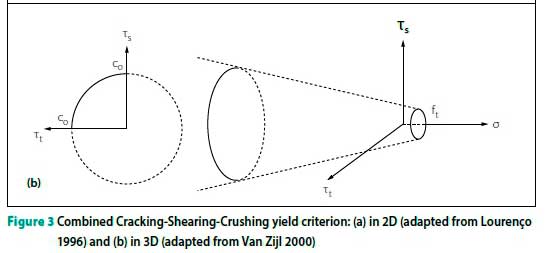
The constitutive material model chosen is the Combined Cracking-Shearing-Crushing (CCSC) model, implemented in DIANA. The plasticity-based model is defined by a multi-surface yield function, shown in Figure 3, consisting of a tension cut-off, a Coulomb friction criterion and an elliptical compression cap. The depiction of the composite yield surface in 3D in Figure 3(b) does not include the elliptical compression cap, but it has been implemented in DIANA (2017).

WALL CONFIGURATIONS
In an effort to make buildings that meet regulatory requirements more affordable to low-income communities and to reduce the immense health and safety risk that unregulated informal structures present (Watermeyer 2004), the Joint Structural Division (JSD) of the South African Institution of Civil Engineering (SAICE) developed a new category of buildings in 2000 (Watermeyer & Milford 2003). This Category 1 building type was introduced in The Application of the National Building Regulations: SANS 10400 in 2004.
These buildings are restricted in size and occupancy class. The floor area is limited to 80 m2, wall lengths to less than 6 m between lateral supports, and the structure to a single storey with no basement. The wall thickness can be as little as 90 mm, compared to 140 mm in non-Category 1 buildings (SANS 2011b). Occupancy classes are restricted to places of instruction or worship, small shops, offices, dormitories, domestic residences and dwelling houses. Category 1 buildings also make allowance for lower performance levels with regard to size and serviceability limits, but no distinction is made between the categories regarding seismic and wind loading.
Deemed-to-satisfy requirements
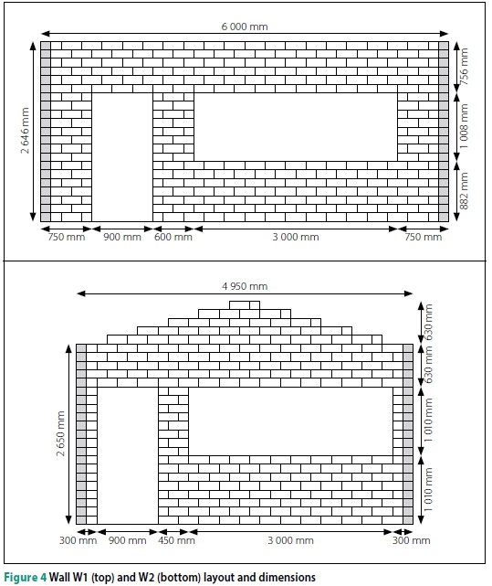
Society's expectation of a wall's performance is implicitly represented by the deemed-to-satisfy masonry wall solutions in SANS 10400-K (SANS 2011b). Therefore, these solutions are used to identify appropriate wall configurations for the LIH context. Additional recommendations and limitations regarding the geometry, roof configuration, energy use and seismic loading, as set out in SANS 10400-A (SANS 2010b), SANS 10400-L (SANS 2011c), SANS 10400-XA (SANS 2011d) and SANS 10160-4 (SANS 2017) respectively, are also taken into consideration. Two different wall configurations, panel wall W1 and gable wall W2, are derived by selecting the most extreme and critical combinations of distance between lateral supports, wall height and openings. These two wall configurations are detailed in Figure 4, where the hatched areas designate positions of return walls which provide lateral support.
The selection criteria for these two representative single-leaf wall layouts are detailed in Table 1. Although only the walls are modelled, the walls are set within the context of representative 40 m2 Category 1 houses to derive loading and support conditions. The roof construction is assumed to be timber, with metal sheet covering.

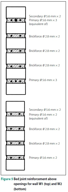
Typical reinforcement according to SANS 10400-K (SANS 2011b) of 5.6 mm steel rods and 2.8 mm brickforce (Figure 5) is modelled in the bed joints above the openings, instead of concrete lintels. The rod reinforcement yield strength is taken as the required proof stress of rod reinforcement by SANS 10400-K (SANS 2011b), namely 485 N/mm2. Whilst brickforce proof stress is not specified in SANS 10400, tensile tests conducted by Talocchino (2005) on typical South African brickforce found a proof yield stress of 500 N/mm2. Therefore, the brick-force yield strength is taken as 485 N/mm2 as well. The elastic modulus of both reinforcement types is taken as 200 000 N/mm2.
Boundary conditions
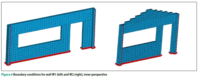
In modelling the support conditions of the wall models, a number of assumptions need to be made. The foundations are modelled as fixed, as depicted in Figure 6, hence fully supported with no potential for differential settlement. Pin supports on the short return walls provide lateral support to the modelled walls, whilst allowing for some rotation of these joints. It is assumed that the roof truss system does not provide substantial lateral load transfer, based on the type of connection and the typical poor quality of the connection between the roof and walling in LIH. Therefore the roof line is modelled as unsupported laterally for both wall configurations.
MATERIAL INPUT PARAMETERS
Material characterisation
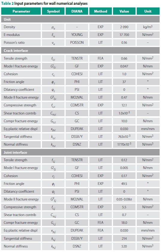
Solid conventional concrete masonry units form the basis of the masonry analysed, together with 10 mm mortar joints. The blocks have a length of 290 mm, width of 140 mm and height of 116 mm. Extensive material parameter characterisation is required for the selected constituent material model, CCSC, that was selected in DIANA. Table 2 contains the material input parameters that were used to define the concrete masonry, as well as the method by which they were determined. Experiments were conducted by Fourie (2017) to determine several of the unit, crack and joint interface parameters, indicated by EXP in Table 2 under Method. Finite element analysis (FEA) was used to determine the tensile strength of the crack interface and the compressive fracture energy and equivalent plastic relative displacement of the joint interface by numerically fitting data to experimental data. Suitable literary sources (LIT) were used to determine the remaining parameters. For further details on the material input parameters or the process to obtain them see De Villiers et al (2018).
Characteristic values of the current material input data cannot be established since the data is statistically insufficient.
The use of nominal values is allowed in such instances according to SANS 10160-1 (SANS 2018a), and it requires the use of mean values for the parameters governing the structural stiffness. The choice of input parameters, as well as the modelling approach, was validated experimentally in a separate process for both the in-plane and out-of-plane behaviour by comparing numerical results to experimental data of dedicated large- and medium-scale masonry wall tests (see De Villiers 2019).
Material partial factors
Material partial factors make a significant contribution to the design process in limit states design. The main considerations in both SANS 51996-1-1 (SANS 2018c) and SANS 10164-1 (SANS 1989) in determining partial factors for materials are manufacturing and construction or execution control. The greater the certainty regarding the unit and mortar strength and the manner in which they are combined on site, the greater the reward is in terms of the load magnitude that the masonry is allowed to bear.
Given the inadequate guidance for the execution control classification in Eurocode 6 (Sýkora & Holický 2010), and the disparity in classifications, a direct comparison of the material partial safety factors is not reasonable. However, in broad terms, the SANS 51996-1-1 (least conservative) ranges from 1.5 to 3.0, the UK National Annex to Eurocode 6 of 2005 (BSI 2005) from 2.3 to 3.0, and SANS 10164-1 (most conservative) from 2.9 to 3.5.
Despite their importance, material partial factors are not included in this study. Admittedly, this may result in a less conclusive evaluation of the concrete masonry walls and the design loads applied to them, which are adjusted with partial factors. However, including the material partial factors renders the finite element output less clear, impacting in particular the fracture behaviour of the concrete masonry as well as the investigation into the relative importance of the parameters.
DESIGN LOADS
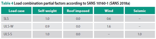
SANS 10400-B (SANS 2012) requires the structural strength and stability of the structure to be assessed by loading it with the relevant actions as determined according to the South African loading code, SANS 10160 (SANS 2011). All relevant design situations are taken into consideration to arrive at the most critical combinations of permanent, imposed, wind and seismic actions for the two wall configurations under consideration. The three load cases considered are the serviceability limit state (SLS) and the ultimate limit states under wind (ULS-W), based on basic fundamental wind speeds of 44, 40 and 36 m/s respectively, and seismic (ULS-S) actions. The latter are determined by means of the equivalent lateral static force method. Table 3 summarises the factored loads applied in the numerical analyses for the vertical loads on the roof and the horizontal out-of-plane (OP) and in-plane (IP) loads on the walls, whereas Table 4 details the partial load factors for the three load cases, according to SANS 10160-1 (SANS 2018a).

Load assumptions
The assumptions made in determining these critical load cases are detailed in the following three sub-sections according to self-weight and imposed load, wind load and seismic load.
Self-weight and imposed load
The self-weight of the walls is based on the density determined experimentally, as detailed in Table 2. The roof assembly consists of six bay Howe type trusses, assuming a timber density of 5 000 N/m3 according to Table A.4 of SANS 10160-2 (SANS 2011a) for the structural pine, and 0.5 mm metal sheeting with a self-weight of 39.5 N/m2 according to Table A.5 of SANS 10160-2 (SANS 2011a). The roof is classified as an inaccessible roof according to Table 5 of SANS 10160-2 (SANS 2011a) and loads for normal maintenance and repair of 400 N/m2 would be included. However, since an additional compressive load on the walls is favourable, the load combination nullifies the roof-imposed load.
Wind load
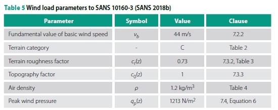
The loads due to wind actions are determined according to SANS 10160-3 (SANS 2018b). The pertinent parameters are summarised in Table 5 and assumptions discussed thereafter.
In most instances, the parameter resulting in the most critical load is selected. The basic fundamental wind speed is taken as the highest value for any area in South Africa of 44 m/s; however, loads based on basic fundamental wind speeds of 40 and 36 m/s are also included in the results for comparative purposes. The terrain category is chosen as the most likely scenario for single-storey residential structures in a suburban or peri-urban setting. The default topography factor is chosen, on the assumption that it is unlikely that low-income housing is developed on extreme terrain, which is costly to construct on. The highest air density value is chosen, to result in the highest critical load.
Additionally, SANS 10400-B (SANS 2012) specifies minimum wind pressures to be applied to housing structural systems of 370 N/m2 and to housing structural elements of 450 N/m2. The peak wind pressures determined according to SANS 10160-3 (1 213 N/m2) (2018) exceed these minimum load requirements.
Seismic load
The loads due to seismic actions are determined according to SANS 10160-4 (SANS 2017). The pertinent parameters are summarised in Table 6 and assumptions discussed thereafter.
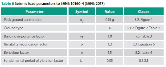
The highest peak ground acceleration for natural seismicity in South Africa is selected. The most unfavourable of ground types is chosen and the selected building importance factor is commensurate with a typical residential structure. The behaviour factor for unreinforced masonry is used, given that minimum detailing and reinforcement requirements are adhered to. The fundamental period of vibration is chosen based on structural system type.
The reliability redundancy factor is not present in the parent standard, Eurocode 8 (EN 1998), but was taken from the Uniform Building Code (ICBO 1997) and introduced in the South African loading code to compensate for a lower nominal peak ground acceleration of 0.1 g (Wium 2010). However, the UBC permits a reliability redundancy factor range of 1.0 to 1.5, compared to a range of 1.2 to 1.5 in SANS 10160-4 (SANS 2017). The lower limit of 1.2 was set to compensate for the higher behaviour factors for reinforced concrete shear walls used in the UBC (ICBO 1997) compared to Eurocode 8 (EN 1998; Wium 2010).
For determining the seismic design load, the reliability redundancy factor is chosen as the lower limit of the allowable range (1.2 to 1.5), hence less conservative, for two reasons. First, a higher peak ground acceleration of 0.15 g was selected for the analyses, not 0.1 g. Second, the lower limit of 1.2 in SANS 10160-4 (SANS 2017) was introduced to compensate for the higher behaviour factors of reinforced concrete shear walls. This discrepancy in behaviour factors is less relevant for this study, given that a consistent behaviour factor for unre-inforced masonry of 1.5 is used. It would hence be justifiable to use a reliability redundancy factor of 1.0. However, compliance with SANS 10160-4 (SANS 2017) is considered salient and a factor of 1.2 is used.
Load application
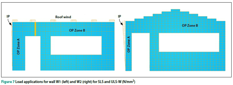
The critical design loads, detailed in Table 3, are applied to the two wall configurations, as shown in Figure 7 for the SLS and ULS-W, and in Figure 8 for the ULS-S. Loads that act out-of-plane (OP) of the wall, are applied as a uniform distributed load over the entire wall, including the wind or seismic load, as applicable. Under wind action, the most critical load case is the modelled wall acting as side wall in the context of a 40 m2 house structure. The OP wind loads are therefore differentiated into Zones A and B, according to SANS 10160-3 (SANS 2018b). The total OP force (N) is applied uniformly over the masonry portions of the model walls to account for the lack of surface area over the wall openings.
The horizontal in-plane (IP) load is distributed over the full height and thickness of the wall. The load arises from the lateral loads on the walls adjacent to the wall modelled, and includes either the wind or seismic load, as applicable. The IP load varies linearly for the wind load case, with the maximum (presented in Table 3) applied at the top of the wall. Using the principle that lateral loads are applied at the location of the mass, the IP load for the seismic load case is distributed uniformly over the height of the wall.
The vertical loads transferred from the roof to the wall are applied at each truss support point and distributed over the width of masonry block to prevent stress concentrations at these points. The roof self-weight and the wind load, if applicable, are included in this load. Vertical uplift is indicated by a positive value, whereas a compressive force is indicated by a negative value. Since W2 is a gable wall configuration, which does not support trusses, the roof load is only applied to the W1 configuration.
In the past, numerical and experimental studies on unreinforced masonry walls have been focussed on the effect of either OP or IP loading. In more recent research, the significance of the interaction of these two load conditions has gained prominence, but still focused on masonry infill walls. Few numerical investigations have taken into account the combined effect of IP and OP actions on load-bearing unreinforced masonry, and even fewer experimental studies (Milani 2008; Agnihotri et al 2013; Najafgholipour et al 2013; Dolatshahi et al 2015). Typically the findings are that the IP load may have a crucial effect on the OP capacity of the wall. The wall slenderness and aspect ratios largely determine the interaction level. Therefore, this study applies the simultaneous action of OP and IP loading.
RESULTS
Results overview
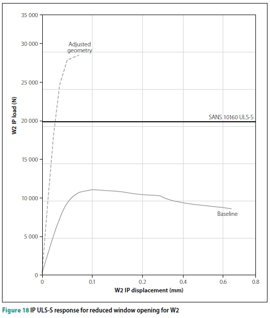
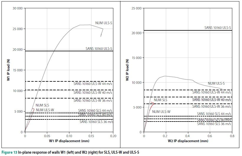
Figure 9 provides an interpretation key for results discussed later. The OP deflections provided in Figures 12 and 17 are measured at the top midspan position, as indicated in Figure 9. The IP displacements provided in Figures 13 and 18 are measured at the top left corner of each respective wall. Typical crack positions found in the numerical analyses are also identified in Figure 9, for the later discussion on crack damage classification and crack width in Figure 14.
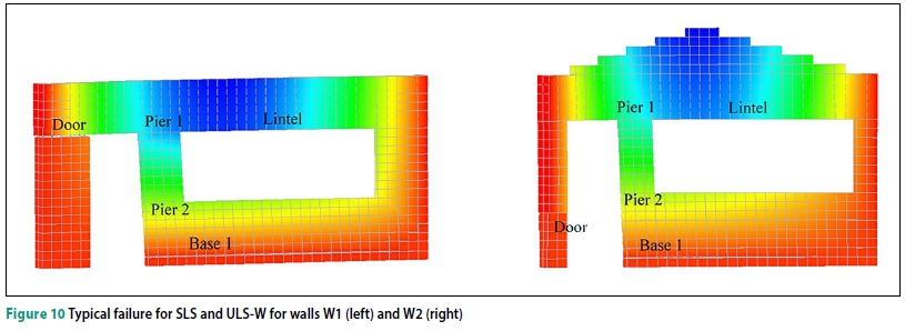
Typical failure modes are presented in Figure 10 for the SLS and ULS-W and in Figure 11 for the ULS-S. Compressive failure or crushing is not identified in either of the wall configurations for both OP and IP failures. This is not remarkable given the small structure size and low vertical loads. The contours in Figure 10 indicate the OP deflections and OP failure dominates for both the SLS and ULS-W, since most of the total load applied is in the lateral direction. The 'Base 1' crack, located in the lowest bed joint of the wall, indicates tensile failure, together with shear failure in columns adjacent to the door openings ('Door') for wall configurations W1 and W2 for both load cases. Subsequent tensile cracks also form in the pier adjacent to the window opening ('Pier 1' and 'Pier 2').
The contours in Figure 11 indicate the IP displacements. IP failure dominates for the ULS-S load case, due to shear action in the walls bearing most of the seismic load. Tensile/flexural cracks dominate, starting with 'Base 2' next to the door and 'Pier 1' to 'Pier 3' surrounding the window opening. Crack onset at 'Base 2' is tensile, and progresses to sliding shear, whereas 'Pier 4' is a combination of shear and tensile stepped cracks. The W2 wall configuration is made particularly vulnerable by the slender column to the left of the door opening.
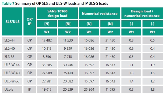
As an overview, the design loads and numerical wall resistance determined through the numerical analyses are presented in Table 7 for the three load cases, namely SLS, ULS-W (for three basic fundamental wind speeds of 44, 40 and 36 m/s) and ULS-S. For each instance of the critical load direction, the ratio of the design load to the numerical wall resistance is included. Failure is therefore indicated by a ratio of greater than 1.0.
Out-of-plane response
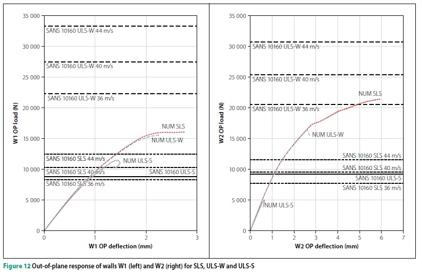
The OP load/deflection responses for W1 and W2 are depicted in Figure 12 for the three load cases. The South African loading code (SANS 10160 2011) OP design loads for each of the three load cases are also included to contextualise the results. In Table 3 the design loads were provided in the form of pressures (N/mm2) but are converted to forces (N) to facilitate the comparison of the design loads and the resistance capacities of the walls.
Of the six analyses presented in Figure 12, in half of them the OP design load significantly exceeds the OP load-carrying capacity of the walls, namely in W1 ULS-W, W2 ULS-W (both for all three basic fundamental wind speeds) and W2 ULS-S. It is important to note that, in line with recent findings in literature (Vaculik 2012; Derakhshan et al 2018), the OP response for the ULS-S is inadequate and that OP behaviour of unreinforced masonry cannot be disregarded under seismic action. SANS 10400-B (SANS 2012) imposes a 1:175 deflection limit on such building walls, which is well above the OP deflection range encountered in these analyses of between 2.5 mm and 7 mm.
The gable of the W2 configuration was not buttressed, contrary to the specifications of SANS 10160-4 (SANS 2017). It was presumed that this lack of lateral support to the gable would cause instabilities in the analyses, but this element was noncriti-cal in the OP loading conditions under consideration. This is most probably due to the presence of more vulnerable, slender elements in the wall in other locations. A wall with better-proportioned openings may well cause the gable to become critical, requiring buttressing.
In-plane response
The IP load/displacement responses for W1 and W2 are depicted in Figure 13 for the three load cases. The South African loading code (SANS 10160 2011) IP design loads for each of the three load cases are also included to contextualise the results.
Reflective of the OP response, in three of the six analyses presented in Figure 13, the IP design load significantly exceeds the IP load-carrying capacity of the walls, namely in W1 ULS-W, W2 ULS-W (both for all three basic fundamental wind speeds) and W2 ULS-S. Notably, the seismic IP capacity of W1 is 2.3 times greater than W2. This is explained in part by the particularly weak geometry derived for W2.
The IP displacement of both of the wall configurations is not significant (less than 1 mm). Arguably, the IP displacement would be greater if the load/displacement path is continued numerically, but the laborious work of overcoming the post-peak divergence prevents this pursuit. There are no limitations specified for IP displacement in SANS 10400 as they are for IP deflections. However, the pronounced reduction in load-carrying capacity, together with the negligible IP displacement, is typical of the extremely brittle behaviour of masonry.
Crack damage classification
The crack damage is classified and presented in Figure 14 for W1 and W2. Only the dominant crack for each load case combination is included for clarity. The frame of reference for the crack widths is taken from the damage categories and maximum crack widths in SANS 10400-B (SANS 2012) and the South African Home Building Manual (NHBRC 2015). The damage categories vary from less than 0.25 mm, classified as negligible, to greater than 25 mm, classified as very severe. These classifications were developed by Watermeyer and Tromp (1992) to serve as serviceability performance criteria for masonry walls and were subsequently included in SANS 10400.
Several typical crack positions were identified in Figures 9, 10 and 11 for the SLS and ULS-W and ULS-S load cases respectively. The most dominant crack is identified for each of the analyses performed and plotted against the OP loads for W1 and W2 in Figure 14. Cracks occurred in a number of typical positions for the IP and OP-dominant loading conditions, as illustrated in Figure 10, as well as in Figure 11 for the ULS-W and in Figure 12 for the ULS-S. For each analysis performed, the most dominant crack is identified and plotted against the OP load in Figure 14 (left) for W1 and (right) for W2. For both W1 and W2, the 'Base' cracks as well as cracks around the window openings in the 'Piers' are prolific. Most cracks measured in the numerical analyses of the concrete masonry walls fall below the 'negligible' (less than 0.25 mm) classification. With further development of the walls' post-peak responses, the cracks would undoubtedly widen. However, in the numerical analyses performed, these initial cracks suffice to demonstrate crack development and to produce a significant reduction in the load-carrying capacity, which is typical of the brittle nature of masonry.
Summary
The progression of most of the analyses was limited by divergence. Several steps were taken to move the analyses past these points of diversion, such as adjusting the step size, increasing the tolerance of the convergence criteria, employing other iterative procedures, etc, and the arc length method was used throughout. However, convergence was rarely achieved. It is clear, though, from the load-displacement or load-deflection trace, that the linear-elastic region has been surpassed and that post-peak global stiffening is improbable.
Given the conventional strength and stiffness range of the concrete masonry studied, as well as the typically conservative nature of deemed-to-satisfy solutions, it was anticipated prior to the study that the resistance of these conventional masonry walls would exceed the design loads in both ULS load cases. Contrary to this expectation, both wall configurations failed to resist the ULS-W design loads for basic fundamental wind speeds of 44, 40 and 36 m/s, as did W2 for the ULS-S design loads, and by a large margin. Plausible origins of these failure are the applied design load, the material input parameters, the derived geometry of the wall configurations and the assumed boundary conditions. These aspects are discussed in the following section.
DISCUSSION
Design load
Most of the assumptions or selections detailed for determining the wind load were made to achieve the most critical wind loading, not the most likely. However, even design wind loads based on 40 and 36 m/s basic fundamental wind speeds, which account for the majority of areas in South Africa, exceed the walls' capacities in most instances.
It is also noteworthy that the wind pressure determined in this study (1 213 N/m2, Table 5) is over three times the minimum wind pressure specified in SANS 10400-B (SANS 2012) (370 N/m2). The substantially higher design load for the ULS-W case is in part due to the recent revision of the wind loading code, SANS 10160-3 (SANS 2018b).
The wind load partial factor has increased from 1.3 to 1.6 and the highest fundamental basic wind speed from 36 m/s to 44 m/s. These two changes combined result in a 1.5 times higher load than would have been the case before these revisions. However, the ratios of design load to resistance are 2.1 and 1.9 for original configurations of W1 and W2, respectively. These revisions alone do not account for the discrepancy, and they were implemented for good reason. The reliability performance of the original wind load partial factor of 1.3 was found to be inadequate (Botha et al 2018) and the South African wind map has improved due to, in part, a seven-fold increase in the historical extreme wind data available in South Africa (Kruger et al 2017).
Material
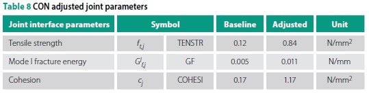
To investigate the potential increase in OP load-carrying capacity due to improved material properties, reasonable maximum values for the three most influential OP parameters (joint tensile strength, joint cohesion and joint mode I fracture energy) were sought in literature. Thereafter, ULS-W load analyses were performed on W1 and W2 with these three adjusted joint parameters. Experimental data on the joint tensile properties is scarce, but reasonable maximum values for mode I fracture energy and cohesion were found in literature for normal density concrete blocks with general purpose mortar joints, conducted by Van Der Pluijm (1999), and are detailed in Table 8. All other parameters, as provided in Table 2, are kept constant.
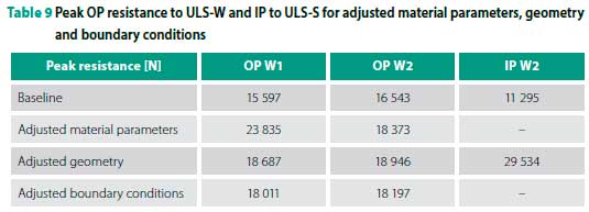
The outcome of these analyses (Table 9 and Figure 17) shows an increase in the load-carrying capacity of 53% for W1 and 11% for W2, due to the improved material properties. This reduces the discrepancy to the most critical design load by 47% and 13% for W1 and W2, respectively. Increasing the critical joint parameters to reasonable maximum values does not increase W2's resistance sufficiently to withstand any of the wind design loads. In the case of W1, the wall's resistance is increased such that the ULS-W load case based on the 36 m/s basic fundamental wind speed can be resisted, but the 40 and 44 m/s not.
It is important to recall that in all the analyses of W1 and W2, mean material parameter values are used, and the material resistance has not been reduced by means of material partial safety factors. Applying this necessary reduction for ULS-based design would further widen the discrepancy.
Geometry
The limitations on wall panel sizes and openings set out in the SANS 10400-K deemed-to-satisfy solutions are taken from the JSD Code of Practice: Foundations and Superstructures for Single Storey Residential Buildings of Masonry Construction (JSD 1995). Different wall panel configurations were analysed using the yield line approach to derive the panel sizes, and the then current South African masonry structural design code SABS 0164-1 (SABS 1980) was applied to the respective elements to derive the opening limitations (Watermeyer 1996).
The total area of openings for both W1 and W2 falls within the specifications of seismic design principles set out in the loading code, SANS 10160-4 (SANS 2017) Clause 6.2.2, of being less than one third of the overall wall area. The openings are positioned "as uniformly as possible", but given the large opening length of 3 m permitted in the deemed-to-satisfy solutions of SANS 10400-K (SANS 2011b), it does result in large openings at both wall ends, which is undesirable according to the seismic design principles of the loading code.
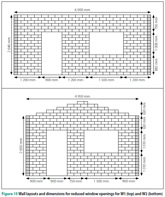
To investigate the potential improvement in OP resistance of both walls under ULS-W loading and IP resistance for W2 under ULS-S loading due to more robust geometry, the original window opening length is halved to 1 500 mm, and the door and window openings are positioned in less extreme positions in the wall, as illustrated in Figure 15 for W1 and W2. All other original dimensions of the walls are maintained.
The outcome of the OP ULS-W analyses (Table 9 and Figure 17) shows an increase in the load-carrying capacity of 20% for W1 and 15% for W2, due to the reduced window opening and the less extreme positions of the openings. This reduces the discrepancy to the most critical design load by 17% for both W1 and W2. The outcome of the IP ULS-S analyses on W2 (Table 9 and Figure 18) shows an increase in the load-carrying capacity of 160% for W2, due to the reduced window opening and the less extreme positions of the openings. The IP resistance of W2 now exceeds the seismic design load by 40%. Reducing the window opening by half does not increase the walls' OP resistances sufficiently to withstand any of the wind design loads. However, this mitigation strategy significantly increases W2's IP load-carrying capacity to successfully resist the full seismic design load.
Boundary conditions
The conservative assumption was made that the timber truss system provides negligible lateral support to the top of the walls. The effect of this assumption could be meaningful, but its validity is sustained given the similarly weak OP resistance of the opposite wall, which is meant to provide the additional lateral resistance, as well as the typically poor quality of connection between truss and wall in LIH.
A potential source of error could be excessive rotation of the short return walls, which provide lateral restraint to the walls. The pinned modelling of the walls could underestimate the rotational restraint that a full-length return wall would offer, thereby allowing greater OP deflection. To investigate the effect of this, the trans-lational restraint on the return walls is applied to all nodes in the boundary plane, as opposed to just the central row of nodes, as shown in Figure 16.
The outcome of the OP ULS-W analyses (Table 9 and Figure 17) shows an increase in the load-carrying capacity of 15% for W1 and 10% for W2, due to the adjusted boundary conditions and increased rotational restraint. This reduces the discrepancy to the most critical design load by 14% for W1 and 12% for W2.
Increasing the rotational restraint provided by the return walls does not increase the walls' resistances sufficiently to withstand any of the wind design loads.
CONCLUSIONS
The FE analyses were executed successfully for the two wall configurations under three load cases. The failure modes can be broadly classified as tensile for the OP-dominant cases and a combination of tensile/shear failure for the IP-dominant cases. The analyses revealed the wall configurations' failure to resist the design loads in most instances, and significantly so in the OP response to the ULS-W load case. This is in part, but not exclusively, due to recent increases to two important parameters in the wind loading code.
Three mitigation strategies were employed, namely improving the tensile performance by increasing three critical joint material parameters, improving the distribution of openings, and increasing the rotational restraint of the return walls. None of these strategies improved the resistance of the walls to the point of successfully resisting the full design wind load. However, reducing the length and improving the distribution of openings significantly increased the IP resistance of W2 to seismic loading.
Additionally, it is important to recall that these analyses were performed without the use of material partial safety factors. Current standardised partial factors for conventional masonry materials range between 1.5 and 3.5. Reducing the material strength by these factors, as is required by limit states design, would further significantly increase the discrepancy between the walls' resistances and the design loads. This raises the issue of possible inconsistencies between the deemed-to-satisfy provisions in SANS 10400-K for wall panel and opening sizes and the current EC-based loading code, both for wind, i.e.
SANS 10160-3 (SANS 2018b) and seismic, i.e. SANS 10160-4 (SANS 2017) loads.
Based on a case study of extreme wind loads on an inland housing development in South Africa, Mahachi et al (2018) came to the conclusion that a review of the technical standards in housing development is necessary, specifically the NHBRC Home Building Manual. Griffith (2000) reports on a similar case of discrepancies between the capacity of the 'deemed-to-comply' wall provisions of the South Australian Housing Code and the Australian masonry standard's design load. It has long been found that, within the field of masonry buildings, low-rise, unreinforced ones with light roofs (such as LIH), experience the most wind damage (Sparks et al 1989), especially non-engineered ones, relying on empirical design procedures. This, coupled with the significant changes in the required wind and seismic design loads with the revision of the South African loading code, warrants a review of the SANS 10400 deemed-to-satisfy wall provisions.
It is recommended that this is done with the preferential housing solution in mind, by first specifying desired wall configurations, based on constructability, typical South African building practice and skill level, fen-estration requirements for building energy usage, natural lighting and ventilation, and fire safety. Numerous such specifications are well documented in the relevant parts of SANS 10400 and can be used as a basis to determine the desired geometry. Subsequently, the derived wall configurations can be structurally analysed using the simplified micro-modelling approach.
ACKNOWLEDGEMENTS
Funding: This work was supported by the National Research Foundation of South Africa (grant numbers 87961, 106965).
REFERENCES
Abdulla, K, Cunningham, L & Gillie, M 2017. Simulating masonry wall behaviour using a simplified micro-model approach. Engineering Structures, 151: 349-365. [ Links ]
Agnihotri, P, Singhal, V & Rai, D 2013. Effect of in-plane damage on out-of-plane strength of unreinforced masonry walls. Engineering Structures, 57: 1-11. [ Links ]
Botha, J, Retief, J & Viljoen, C 2018. Reliability assessment of the South African wind load design formulation. Journal of the South African Institution of Civil Engineering, 60(3): 30-40. [ Links ]
BS (British Standard) 1978. BS 5628-1:1978. Code of Practice for the Use of Masonry. Structural Use of Unreinforced Masonry. London: British Standards Institution. [ Links ]
BSI (British Standards Institution) 2005. NA to BS EN 1996-1-1. UK National Annex to Eurocode 6. Design of Masonry Structures. General Rules for Reinforced and Unreinforced Masonry Structures. London: BSI. [ Links ]
CMA (Concrete Manufacturers Association) 2011. Initiatives. http://www.cma.org.za/Initiatives/The-CMA-House. [ Links ]
De Villiers, W I 2019. Computational and experimental modelling of masonry walling towards performance-based standardisation of alternative masonry units for low-income housing. PhD Thesis. Stellenbosch University. [ Links ]
De Villiers, W I, Fourie, J & Boshoff, W P 2018. Numerical modelling of alternative masonry units. Proceedings, International RILEM Symposium on Concrete Modelling (CONMOD18), 26-29 August 2018, Delft, The Netherlands. [ Links ]
Department of Human Settlements (DHS) 2017. Delivery of Serviced Sites and Houses/Units from HSDG. Pretoria: DHS. [ Links ]
Derakhshan, H, Lucas, W, Visintin, P & Griffith, M 2018. Out-of-plane strength of existing two-way spanning solid and cavity unreinforced masonry walls. Structures, 13: 88-101. [ Links ]
DIANA 2017. Finite Element Analysis User's Manual 10.2. Delft: DIANA FEA BV. [ Links ]
Dolatshahi, K, Aref, A & Whittaker, A 2015. Interaction curves for in-plane and out-of-plane behaviours of unreinforced masonry walls. Journal of Earthquake Engineering, 19: 60-84. [ Links ]
EN (European Standard) 1990. EN 1990 (2002). Eurocode: Basis of Structural Design. Brussels: European Committee for Standardization (CEN). [ Links ]
EN (European Standard) 1991. EN 1991 (2002+). Eurocode 1: Actions on Structures. Brussels: CEN. [ Links ]
EN (European Standard) 1998. EN 1998-1 (2004). Eurocode 8: Design of Structures for Earthquake Resistance. Part 1: General Seismic Actions and Rules for Buildings. Brussels: CEN. [ Links ]
Fourie, J 2017. Characterisation and evaluation of the mechanical properties of alternative masonry units. MEng Dissertation. Stellenbosch University. [ Links ]
Giambanco, G, Rizzo, S & Spallino, R 2001. Numerical analysis of masonry structures via interface models. Computer Methods in Applied Mechanics and Engineering, 190: 6493-6511. [ Links ]
Griffith, M 2000. Experimental Study of the Flexural Strength of URM (Brick) Walls. Adelaide, Australia: University of Adelaide. [ Links ]
ICBO (International Conference of Building Officials) 1997. Uniform Building Code (UBC)™. Whittier, CA: ICBO. [ Links ]
JSD (Joint Structural Division) 1995. Code of Practice: Foundations and Superstructures for Single Storey Residential Buildings of Masonry Construction. Halfway House: SAICE and IStructE Joint Structural Division. [ Links ]
Kruger, A, Retief, J & Goliger, A 2017. Development of an updated fundamental basic wind speed map for SANS 10160-3. Journal of the South African Institution of Civil Engineering, 59(4): 12-25. [ Links ]
Laubscher, J 2014. Reviewing challenges between the need for government-subsidised housing in South Africa and the sustainability requirements of the National Building Regulations. Proceedings, World SB14, 28-30 October 2014, Barcelona, Spain, pp 18-24. [ Links ]
Lourengo, P B 1996. Computational Strategies for Masonry Structures. Delft, The Netherlands: Delft University Press. [ Links ]
Lourengo, P B & Rots, J 1997. Multisurface interface model for analysis of masonry structures. Journal of Engineering Mechanics, 123: 660-669. [ Links ]
Macorini, L & Izzuddin, B 2011. A non-linear interface element for 3D mesoscale analysis of brick-masonry structures. International Journal for Numerical Methods in Engineering, 85: 1584-1608. [ Links ]
Mahachi, J, Bradley, R & Goliger, A 2018. Wind storm damage to houses: Planning and design consideration. Proceedings, Out-Of-The-Box Conference, 24-25 October 2018, Pretoria, pp 82-92. [ Links ]
Milani, G 2008. 3D upper bound limit analysis of multi-leaf masonry walls. International Journal of Mechanical Sciences, 50: 817-836. [ Links ]
Najafgholipour, M, Maheri, M & Lourengo, P B 2013. Capacity interaction in brick masonry under simultaneous in-plane and out-of-plane loads. Construction and Building Materials, 38: 619-626. [ Links ]
NHBRC (National Home Builders Registration Council) 2015. Home Building Manual and Guide. Johannesburg: NHBRC. [ Links ]
Reyes, E, Casati, M J & Gälvez, J C 2008. Cohesive crack model for mixed mode fracture of brick masonry. International Journal of Fracture, 151: 29-55. [ Links ]
Roca, P, Cervera, M, Gariup, G & Pela, L 2010. Structural analysis of masonry historical constructions: Classical and advanced approaches. Archives of Computer Methods in Engineering, 17: 299-325. [ Links ]
RSA (Republic of South Africa) 1977. National Building Regulations and Building Standards Act, 103 1977, Government Gazette, No 145 (5640), 6 July 1977, Pretoria: Government Printer. [ Links ]
RSA (Republic of South Africa) 1995. Housing Consumers Protection Measures Act, 9 of 1995. Government Gazette, 401(19418), 2 November 1995, Pretoria: Government Printer. [ Links ]
SABS 1980. SABS 0164-1:1980. Code of Practice. The Structural Use of Masonry, Part 1: Unreinforced Masonry Walling. Pretoria: South African Bureau of Standards. [ Links ]
SANS (South African National Standard) 1989. SANS 10164-1 1989. The Structural Use of Masonry, Part 1: Unreinforced Masonry Walling. Pretoria: SABS Standards Division. [ Links ]
SANS 2010a. SANS 10400 2010. The Application of the National Building Regulations, 3rd ed. Pretoria: SABS Standards Division. [ Links ]
SANS 2010b. SANS 10400-A 2010. The Application of the National Building Regulations. Part A: General Principles and Requirements, 3rd ed. Pretoria: SABS Standards Division. [ Links ]
SANS 2011. SANS 10160 2011. Basis of Structural Design and Actions for Buildings and Industrial Structures, 1.1 ed. Pretoria: SABS Standards Division. [ Links ]
SANS 2011a. SANS 10160-2 2011. Basis of Structural Design and Actions for Buildings and Industrial Structures. Part 2: Self-weight and Imposed Loads. Pretoria: SABS Standards Division. [ Links ]
SANS 2011b. SANS 10400-K 2011. The Application of the National Building Regulations. Part K: Walls, 3rd ed. Pretoria: SABS Standards Division. [ Links ]
SANS 2011c. SANS 10400-L 2011. The Application of the National Building Regulations. Part L: Roofs, 3rd ed. Pretoria: SABS Standards Division. [ Links ]
SANS 2011d. SANS 10400-XA 2011. The Application of the National Building Regulations. Part X: Environmental Sustainability; Part XA: Energy Usage in Buildings. Pretoria: SABS Standards Division. [ Links ]
SANS 2012. SANS 10400-B 2012. The Application of the National Building Regulations. Part B: Structural Design, 3rd ed. Pretoria: SABS Standards Division. [ Links ]
SANS 2017. SANS 10160-4 2017. Basis of Structural Design and Actions for Buildings and Industrial Structures. Part 4: Seismic Actions and General Requirements for Buildings. Pretoria: SABS Standards Division. [ Links ]
SANS 2018a. SANS 10160-1 2018. Basis of Structural Design and Actions for Buildings and Industrial Structures. Part 1: Basis of Structural Design. Pretoria: SABS Standards Division. [ Links ]
SANS 2018b. SANS 10160-3 2018. Basis of Structural Design and actions for Buildings and Industrial Structures. Part 3: Wind. Pretoria: SABS Standards Division. [ Links ]
SANS 2018c. SANS 51996-1-1 2018. Eurocode 6: Design of Masonry Structures. Part 1-1: General Rules for Reinforced and Unreinforced Masonry Structures, 1st ed. Pretoria: SABS Standards Division. [ Links ]
Sisulu, L 2016. Housing Backlog at 2.1 million, says Minister Sisulu. Engineering News, 22 April 2016. [ Links ]
Sparks, P, Liu, H & Saffir, H 1989. Wind damage to masonry buildings. Journal of Aerospace Engineering, 2(4): 186-198. [ Links ]
Sýkora, M & Holický, M 2010. Probabilistic model for masonry strength of existing structures. Engineering Mechanics, 174(1): 61-70. [ Links ]
Talocchino, G 2005. Design and construction criteria for domes in low-cost housing. MEng Dissertation, Johannesburg: University of the Witwatersrand. [ Links ]
Vaculik, J 2012. Unreinforced masonry walls subjected to out-of-plane seismic actions. PhD Thesis. Adelaide, Australia: University of Adelaide. [ Links ]
Van Der Pluijm, R 1999. Out-of-plane bending of masonry: Behaviour of bed joints. PhD Thesis. Eindhoven, The Netherlands, Technische Universiteit Eindhoven, pp 1849-1862. doi.org/10.6100/IR528212. [ Links ]
Van Zijl, G P A G 2000. Computational modelling of masonry creep and shrinkage. PhD Thesis. Delft, The Netherlands: Delft University of Technology. [ Links ]
Watermeyer, R 1996. Recent developments in providing houses of masonry construction in South Africa. The Structural Engineer, 74(19): 325-331. [ Links ]
Watermeyer, R 2004. The impact of structural engineering on the sustainability of human settlements in developing countries. Proceedings, 2nd International Conference on Structural Engineering, Mechanics and Computation, Cape Town. [ Links ]
Watermeyer, R & Tromp, B 1992. A systematic approach to the design and construction of single-storey residential masonry structures on problem soils. The Civil Engineer in South Africa, March: 83-96. [ Links ]
Watermeyer, R & Milford, R 2003. The use of performance-based building codes to attain sustainable housing objective: The South African approach. Presented at the Global Policy Summit on the Role of Performance-Based Building Regulations in Addressing Societal Expectations, International Policy, and Local Needs. Washington, DC, US. [ Links ]
Wium, J A 2010. Background to draft SANS 10160 (2009) Part 4. Seismic loading. Journal of the South African Institution of Civil Engineering, 52(1): 20-27. [ Links ]
 Correspondence:
Wibke De Villiers
Department of Civil Engineering, Stellenbosch University Private Bag X1
Matieland 7602, Stellenbosch, South Africa
T: +27 21 808 4072, E: wdv@sun.ac.za
Gideon Van Zijl
Department of Civil Engineering, Stellenbosch University Private Bag X1
Matieland 7602, Stellenbosch, South Africa
T: +2 7 21 80 8 4 436, E: gvanzijl@sun.ac.za
Billy Boshoff
Address at the time of preparing this paper: Department of Civil Engineering, Stellenbosch University Private Bag X1
Matieland 7602, Stellenbosch, South Africa
Current address:
Faculty of Engineering, Built Environment and Information Technology University of Pretoria
Private Bag X20, Hatfield 0028, South Africa
T: +27 12 420 2746, E: billy.boshoff@up.ac.za

DR WIBKE DE VILLIERS is a senior lecturer at Stellenbosch University, where she obtained her BEng (2006), MSc Eng (2008) and PhD (2019), the latter in the development of performance-based specifications for alternative masonry units. As part of the Unit of Construction Materials, her research interests lie in alternative and sustainable construction materials, and their structural and thermal performance. She has supervised a number of postgraduate students and authored or co-authored several publications over the past nine years. Prior to this, she spent two years at Aurecon as a structural design engineer.

PROF GIDEON VAN ZIJL (Pr Eng) is a professor in structural engineering at Stellenbosch University. He obtained his Bachelor's (1986) and Master's (1990) degrees in Civil Engineering from Stellenbosch University, and his PhD (2000) from Delft University in the Netherlands. As Director of the Centre for Development of Sustainable Infrastructure, his research interests are 3D construction printing, structural and computational mechanics, including the development, characterisation, and constitutive and durability modelling of advanced construction materials.

PROF BILLY BOSHOFF (Pr Eng) is a professor in civil engineering at the University of Pretoria. He was head ofthe Structural Engineering Division at Stellenbosch University for seven years, and served as the president of the Concrete Society of Southern Africa from 2012 to 2014. He completed his PhD at Stellenbosch University in the field of fibre-reinforced concrete in 2007, and has published over 100 papers in journals and conference proceedings. His research interest is in the field of construction materials, but more specifically fibre-reinforced concrete, concrete cracking in the fresh state, as well as unconventional and eco-friendly construction materials.

