


Services on Demand
Article
 English (pdf)
 Article in xml format
 Article references
Indicators

Related links
-
 Cited by Google
 -
 Similars in Google
Share

 Permalink
Journal of the South African Institution of Civil Engineering
On-line version ISSN 2309-8775
Print version ISSN 1021-2019
J. S. Afr. Inst. Civ. Eng. vol.62 n.4 Midrand Dec. 2020
http://dx.doi.org/10.17159/2309-8775/2020/v62n4a2
TECHNICAL PAPER
The interception capabilities of slotted drains as pavement surface drainage systems
B Jansen van Vuuren; M van Dijk; W J vdM Steyn
ABSTRACT
The following two slotted drain installation scenarios were reviewed in this paper: a slotted drain operating individually without a median barrier and a slotted drain operating with an adjacent barrier installed along the longitudinal length of the drain. The interception capability of the two installation scenarios was experimentally reviewed and compared while imitating various conditions typically expected on South African pavements. The applied sheet flow, slotted inlet sizes and pavement slopes (longitudinal and cross slopes) were varied throughout the experiment. Interception efficiencies of the slotted inlets were experimentally calculated as a ratio of total intercepted sheet flow to the total sheet flow applied to the pavement layouts. The sheet flow applied during the experiment was analysed to estimate the rainfall intensities and flow depths that can typically occur on the different pavements for which the interception capability of the slotted inlets was reviewed. It was estimated that rainfall intensities of more than 1 000 mm/hr and flow depths higherthan 10 mm were imitated during the experiment. More than 98% of the maximum applied sheet flow of approximately 3.0 £/s/m was intercepted by the 30 mm slotted inlets regardless of the pavement slope values and type of slotted drain layout. The conclusion reached was that both these slotted drain installation scenarios operating in practice for the conditions tested would have the capability to sufficiently remove the surface water to promote road safety during wet pavement conditions.
Keywords: slotted, inlets, drainage, interception, efficiency
INTRODUCTION
One of the most common hydraulic risks on a pavement surface is the accumulation of surface runoff caused by insufficient surface drainage, Hydroplaning and splash and spray, the two phenomena associated with insufficient surface drainage and ponding water on a pavement surface, are directly proportional to the water film depth on a pavement surface. Three techniques to reduce the water depth on a pavement surface are:
■ regulating the pavement geometry utilising different pavement surface textures
■ implementing efficient surface drainage systems.
The placement of slotted drains between adjacent lanes on wider pavements with three to four carriageways is a recommended drainage technique to enhance surface drainage (Anderson et al 1998), Slotted drains are normally identified as pipe segments cut along the longitudinal length to form an opening and are often spaced with bars perpendicular to the pipe opening to form slotted inlets, Slotted drains are installed within a pavement structure to intercept sheet flow by functioning individually, or are installed to operate with a concrete barrier placed along the slotted drain's longitudinal length. The decision whether to implement a median barrier with a slotted drain usually depends on the geometric design and the total width of the pavement. Various slotted drain installations are implemented on South African pavements (for example on the Gauteng Freeway Improvement Project (GFIP) and on airport runways) to improve surface drainage, However, for numerous pavement designers the implementation of slotted drains as surface drainage systems in South Africa is still a questionable drainage solution due to uncertainty around the drainage capabilities and maintenance possibilities of these drains.
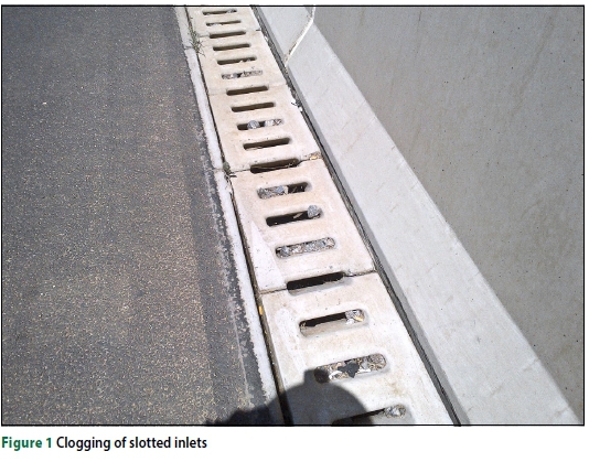
The operation of slotted drains on pavements has potential disadvantages. Slotted drains are highly susceptible to clogging (Figure 1) and the implementation of slotted drains in environments where significant sediment and debris are presented is not recommended, as severe ponding can develop on the pavement surface, creating safety hazards for pavement users (Brown et al 2009), Slotted drains, subjected to traffic loads within trafficking areas, are likely to deteriorate and cause unevenness on the roadway surface, The location, spacing and the inlet size of the slotted drains installed on pavement surfaces should thus be kept in mind when designing for these pavement drainage systems.
The cleaning of slotted inlets can be relatively easy but should be maintained on a regular basis in high-sediment areas, Special equipment is used, such as cleaning paddles or cleaning brushes which match the shape and the profile of the bottom of the drain for cleaning smaller slotted drains, A water compressor can also be used to clean more significant drains where a high force of water and air is blown into the slotted inlets to remove clogging materials, Debris is then manually removed from the catch basin, The clogging of debris can become problematic, as heavy stormwater can easily transport sediments and debris over a large pavement area, causing clogging of the slotted inlets.
Slotted drains functioning as pavement surface drainage systems can be evaluated on their capability to intercept and remove surface water, as well as their ability to dispatch debris, The primary objective of this paper was to evaluate slotted drain performance by experimentally reviewing the interception efficiencies of two different slotted drain layouts, Various factors affecting the interception efficiencies of slotted drains were imitated during the experiment to evaluate whether these drains are able to sufficiently remove surface water from a pavement.
Hydroplaning and splash and spray
Hydroplaning, also defined as aquaplaning, is the partial or full separation between the wheels of a vehicle and the pavement surface, caused by the excessive water pressure accumulated between the vehicle's wheels and the pavement surface, An increase in the water pressure (which is initially equal to the forces exerted by the wheels) causes a reduction in skid resistance, which ultimately leads to non-existent steering ability, Hydroplaning is directly proportional to the depth of the water film on the pavement surface and is highly influenced by fundamental factors such as the driving characteristics, vehicle dynamics, pavement conditions (geometric design, drainage design and maintenance) and several environmental factors (Chaithoo & Allopi 2012), According to Brown et al (2009), hydroplaning can occur at travelling speeds from 89 km/hr with water depths starting at 2 mm, NAASRA (1974) states that water depths ranging between 2,5 mm and 5 mm can cause friction loss between tyres and the pavement surface without actual aquaplaning occurring, However, the critical water film depth for aquaplaning to initiate may vary between 4 mm and 10 mm depending on other characteristics of the pavement surface (NAASRA 1974).
The South African Road Agency Limited (SANRAL 2013) recommends that the water film thickness on the pavement surface during a l:5-year storm should not exceed 6 mm to reduce aquaplaning risks to within acceptable limits.
Another safety concern associated with wet pavement conditions is the "splash and spray" effect, When a vehicle travels on a wet pavement surface, the tyres of the vehicle accumulate the water from the pavement surface and spread clouds of small droplets into the air, resulting in poor visibility and unsafe driving conditions for road users.
Water film depths
A review of relevant literature has shown that the water film depth (WFD) on a pavement surface can accurately be predicated with a variety of empirical or analytical methods, These methods apply influencing variables such as drainage flow path slopes, drainage flow path lengths, rainfall intensities, Manning n-values, time of concentration and texture depths.
The RRL (Road Research Laboratory) method (Russam & Ross 1968) is an approved method to determine the water film depth on pavements in South Africa.
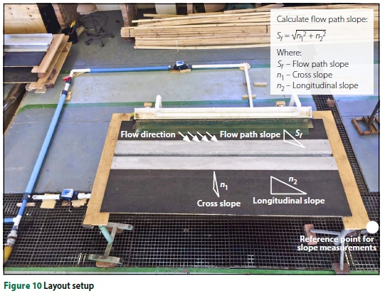
This method is defined by two concepts, namely the gradient (slope) and distance (length) of the drainage flow on the pavement surface, The drainage flow path length is the minimum distance that the water must flow from the point at which it falls on the surface to the edge of the pavement and is measured along its flow path slope which depends on a combination of the pavement width, cross slope and longitudinal slope, The following equations are used and adapted from the SANRAL drainage manual (SANRAL 2013) to estimate the water film depth on a pavement surface according to the RRL method:
To calculate the slope of the flow path (laminar flow conditions are assumed):
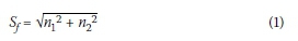
Sf =flow path slope (%)
n1 = pavement cross fall (%)
n2 = pavement gradient (%)
(The flow path slope is determined assuming a planar road surface, without super-elevation.)
To calculate the length of the flow path (laminar flow conditions are assumed):
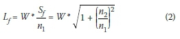
Lf = length of flow path (m)
W = pavement width (m)
The water flow depth can consequently be determined as:

d = water flow depth (mm)
I = rainfall intensity (mm/h)
Gallaway et al (1979) developed a different empirical method for the United States Department of Transportation in cooperation with the Federal Highway Administration (FHWA) to accurately predict the water film depth (WFD) on a pavement surface, This method, detailed in the Texas Department of Transportation's (TxDOT) hydraulic design manual (Bohuslav 2004) is an empirical relationship between the drainage flow path length, the pavement slope, the rainfall intensity and the mean texture depth of the pavement surface, Gallaway (1979) and Oakden (1977) both recommended that the WFD on a pavement surface should be limited to a maximum depth of 4 mm.
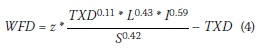
WFD = water film depth above the top of the surface asperities (mm)
z = constant (0,01485)
TXD = mean pavement texture depth (mm, 0,5 mm for design)
L = length of drainage path (m)
I = rainfall intensity (mm/h, with a minimum of 50 mm/hr)
S = slope of drainage path (%)
(The values for the variables provided were obtained from TxDOT's hydraulic design manual (Bohuslav 2004)).
Chaithoo and Allopi (2012) developed an independent software tool to determine flow depths on pavement surfaces by considering various hydraulic factors, The calculations confirmed that the flow depth of surface water will increase when the width of the road increases or the road gradient increases, Conversely, the flow depth will decrease if the road cross fall increases.
Anderson et al (1998) have studied and identified three different techniques to control water film thickness on pavement structures:
Controlling the pavement geometry
■ Implementing textured pavement surfaces (asphalt, grooved concrete, ultra-thin friction course (UTFC))
■ Installing effective drainage appurtenances.
The surface drainage systems implemented to reduce water film depths on pavements should have the capability to intercept surface water efficiently with a minimum susceptibility to clog.
Interception efficiency of slotted inlets
The interception efficiency (E) of an inlet is the ratio between the total amount of water flow intercepted and the total amount of flow approaching the inlet, expressed as a percentage, This is dependent on a number of influencing factors, such as the inlet characteristics (length, width, curb opening, etc), the pavement slopes (longitudinal and cross slopes), the velocity, and the flow depth of the approaching flow, The interception efficiency of an inlet decreases as the approaching flow velocity increases towards the inlet, as well as when the flow width of the approaching flow is greater than the inlet width (Brown et al 2009).
The interception efficiency of an inlet is expressed by the following equation:

E = interception efficiency (%)
Q = total flow (m3/s)
Qi = intercepted flow (m3/s)
Some slotted inlets are installed in the centre of highways or multi-carriageway pavements to operate individually or with a type of barrier placed along the longitudinal length of the drain, This barrier can improve the road safety during wet pavement conditions, as the surface water which is not intercepted by the inlets accumulates against the barrier without flowing to the opposite side of the roadway, These two installation scenarios were experimentally evaluated in this paper.
METHODS
Description of test facility
Two different experimental layouts were designed and constructed to simulate slotted drains operating under two different installation scenarios in practice (Figure 2).
Layout 1 (A) was built to simulate the operation of a slotted drain functioning individually without an adjacent median barrier, which in practice is installed with the same gradient as the cross slope of the pavement, Layout 2 (B) was built to simulate the operation of a slotted drain functioning with an adjacent median barrier, which in practice is installed with the same gradient as the median barrier (horizontally to the cross slope of the pavement with a zero per cent slope).
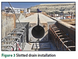
The layouts were designed and constructed with similar full-scale dimensions as the precast concrete slotted drains manufactured by Salberg Concrete Products (Pty) Ltd in South Africa, The inlet sizes of the proprietary slotted drains reviewed in the experiment were 20 mm, 40 mm and 60 mm wide, Figure 3 shows the proprietary slotted drain installation in practice, followed by Figure 4 that shows the cross-sectional slotted drain design, with the respective dimensions summarised in Table 1, The test procedures and results discussed in this paper were only for the two layouts with the 20 mm slotted inlet width.


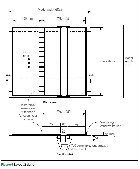
Each layout was constructed from 1,22 m x 2,44 m shutter wood representing a pavement section, a slotted inlet and a fixed catchment drainage area underneath the slotted inlet of the layout to capture intercepted surface water for flow measurements. The surface of the pavement sections was treated with bitumen paint and sieved sand particles (between 1 mm and 2 mm) to obtain an asphalt-like surface texture, An average surface texture depth of 0,628 mm was achieved by the sand patch test method (CSRA 1984), The different layouts were placed individually on portable and adjustable support footings to achieve different pavement slope configurations during the experiment. The pavement section and the slotted inlet of Layout 1 were fixed to adjust as a unit on the support footings, while the pavement section of Layout 2 was partially fixed to the slotted inlet with a stitchbond fabric membrane. The membrane performed as a hinge which allowed the pavement section to adjust independently from the slotted inlet system on the support footings for different slope configurations. More additions were made to Layout 2 imitating the operation of a median barrier.
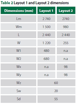
A small piece of shutter board with a height of 95 mm was fixed to the end of the slotted inlet, which in practice represents the bottom part of the median barrier, Figures 5 and 6 are schematic illustrations of Layout 1 and Layout 2 respectively, followed by the layout dimensions as specified in Table 2.

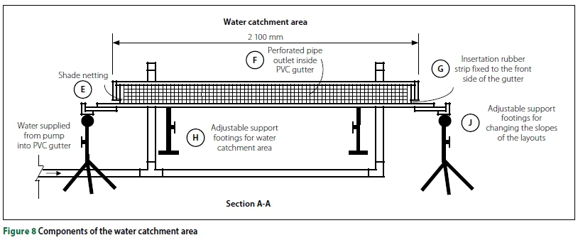
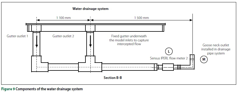
The experiment was conducted in the hydraulic laboratory of the University of Pretoria next to a large sump which served as a water reservoir for the experiment, The experimental setup consisted of a water supply system, a water catchment area, the constructed pavement section and a water drainage system, The experimental setup is illustrated schematically in Figures 7, 8 and 9 with the components listed in Table 3.
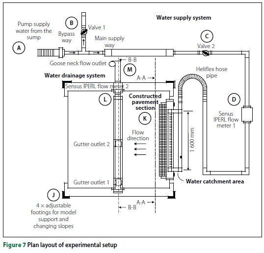
In Figure 7 a submersible pump (A) was used to deliver water from the sump through a network of pipes, filling a self-constructed catchment area (PVC gutter), Two PVC ball valves were used to control the volume of water applied to the system, Valve 1 (B), was manually operated to bypass the excess volume of water to discharge back into the sump, while Valve 2 (C) was used to control the flow rate delivered through the pipe network into the water catchment area, A Sensus IPERL flow meter (D) was used to measure the applied flow rate.
In Figure 8 the self-constructed water catchment area was a 2,1 m long gutter section fixed to two adjustable footings for support (H), The catchment area was located just above the pavement section of the layout and was elevated as required for the different slope setups of the layouts, Water settled in the gutter before discharging uniformly over the side onto the pavement section of the layouts, An insertion rubber strip (G) was sealed to the frontal side of the gutter to prevent water leakage underneath the gutter, Shade netting (E), was fixed to the front side of the gutter to enhance sheet flow conditions by reducing the water turbulence when exiting the gutter.
In Figure 9 the sheet flow intercepted by the slotted inlet was captured in the gutter fixed underneath the slotted inlets of the layouts, A drainage system was connected to two gutter outlets to drain the intercepted water, preventing the gutter to overflow, Another Sensus IPERL flow meter (L) was connected to a pipe on the drainage system to measure the total volume of water intercepted by the slotted inlet, Any water not intercepted by the slotted inlet flowed directly into the sump below the installation, A gooseneck flow outlet (M) was installed at the end of the drainpipe, ensuring that the drainpipe was constantly full to conduct accurate flow measurements.
Figure 10 shows the experimental setup with the water flow direction and slopes.
Test procedures and measurements
Different flow rates were reviewed in the experiment, The flow rates were regulated by opening or closing the two valves (B and C in Figure 7), Flows were recorded after a few minutes when a smooth sheet flow runoff had been obtained on the pavement surface, Flow measurements were manually logged every 180 seconds for four consecutive periods at a constant discharge, Flow depths were measured with a digital point gauge across the width of the sheet flow at three different positions - left, middle and right, The pavement slope was altered by adjusting the heights of the support footings individually, Once the specific slope of the pavement layout had been obtained, the test procedure was repeated for different flows, A droplet of liquid dye was applied to the sheet flow to obtain a visual illustration of the flow path for different slopes. Data obtained from the flow measuring devices (with a calibrated accuracy of 2%) was used to determine inlet interception efficiencies for each test configuration as the ratio between the total intercepted flow and the total applied sheet.
Layout components and test variables
Table 4 reflects the characteristics and test values of the layouts.

DATA ANALYSIS AND RESULTS DISCUSSION
Six different slope combinations were tested for the five different flow rates that were applied to the layouts, Longitudinal and cross slopes were varied up to 6% as flow measurements were taken three times per constant applied sheet flow, The applied flow rates were measured with the flow meter connected to the water supply system, and intercepted flow rates were measured with the flow meter connected to the drainage system of the experimental setup. The interception efficiency (%) was determined by dividing the average intercepted flow rate by the average applied flow rate (see Equation 5), These results are summarised in Tables 5 and 6.

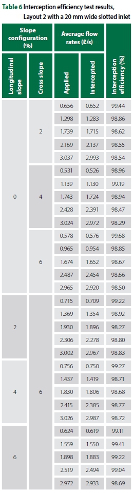
Both layouts with a 20 mm wide slotted inlet intercepted more than 98% of the applied sheet flow up to approximately 3,0 l/s. It was found that the median barrier of Layout 2 did not have any effect on the interception efficiency of the inlet, as the sheet flow was intercepted without overflowing the inlet before the barrier could be in function.
Additionally, the applied flow rate per square metre was analysed to estimate the rainfall intensities (I) and water flow depths (d) that can typically occur on different pavement widths, for which the interception capability of the slotted inlets was reviewed, Calculations were made for pavement widths up to four carriageways, assuming that each carriage way is 3,6 m wide, The variables used in the calculations are shown in Figure 11.

The rational method was used to convert the applied sheet flow to rainfall intensity for a specific flow area (SANRAL 2013):
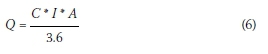
Q = peak flow (m3/s)
C = run-off coefficient (C = 1 for this study) (dimensionless)
I = average rainfall intensity over a catchment (mm/hr)
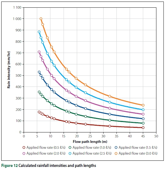
The rainfall intensities were plotted against the different flow path lengths (per metre width) obtained from the applied flow rates during the experiment (Figure 12). The flow path length, calculated using Equation 2, is a function of the slope of the pavement (longitudinal and cross slope) and the pavement width (calculated for 3,6 m, 7,2 m, 10,8 m, 14,4 m). A longer flow path represents a larger pavement area (m2) and vice versa, Figure 12 shows that longer flow lengths resulted in smaller rainfall intensities for a constantly applied flow rate, Similarly, for a constant flow path length, higher applied flow rates represent higher rainfall intensities tested in the experiment.
The flow depths that will occur on the different pavement widths were estimated using the RRL method (Equation 3), Gallaway method (Equation 4) and the broad-crested weir equation (Equation 7 below) (SANRAL 2013):
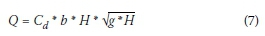
Q = flow rate (m3/sj
Cd = discharge coefficient (0,6)
b = total width of flow (m)
H = energy head (flow depth) (m)
g = gravitational acceleration (9,81 m/s2)
The estimated flow depths were summarised in Table 7 for a maximum flow rate of 3,0 l/s.
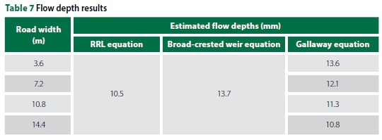
Depending on the slopes and width of the pavement, which affect the flow path length, calculations have shown that the flow rates applied during the experiment can simulate rainfall intensities of more than 1 000 mm/hr and flow depths of higher than 10 mm, The layouts reviewed under the test conditions have sufficiently intercepted more than 98% of the applied sheet flow.
CONCLUSIONS
The following conclusions were drawn by reviewing the interception capability of the slotted drain installation scenarios presented in this paper:
■ Both pavement layouts with an inlet width of 20 mm intercepted more than 98% of the applied flow rate with a capacity of approximately 3,0 l/s/m length.
■ The imitation of placing a median barrier along the longitudinal length of the slotted inlets did not affect the interception capabilities of the inlets, as all the sheet flow was intercepted before the barrier could be in operation.
■ Both outlets tested in the experiment have the capability of intercepting surface water with flow depths higher than the recommended flow depth of not exceeding 6 mm to reduce aquaplaning risks to within acceptable limits (SANRAL 2013).
■ The installation of the slotted drains as pavement surface drainage systems is concluded to be a safe and efficient method to remove surface water from pavement surfaces.
REFERENCES
Anderson, D A, Huebner, R S, Reed, J R, Warner, J C & Henry, J J 1998. Improved surface drainage of pavements. Washington, DC: National Cooperative Highway Research Program (NCHRP). https://doi.org/10.17226/6357. [ Links ]
Bohuslav, K 2004. Hydraulic Design Manual. Austin, TX: Texas Department of Transportation. [ Links ]
Brown, S A, Schall, J D, Morris, J L, Doherty, C L, Stein, S M & Warner, J C 2009. Urban Drainage Manual, 3rd ed. Hydraulic Engineering Circular (HEC) No. 22 Publication No. FHWANHL10-009. Washington, DC: Federal Highway Administration, US Department of Transportation. [ Links ]
Chaíthoo, D B & Allopí, D R 2012. A software tool approach to re-evaluating super elevation in relation to drainage requirements and vehicle dynamics -A case study. Proceedings, 31st South African Transport Conference (SATC), 9-12 July 2012, Pretoria. [ Links ]
CSRA (Committee of State Road Authorities) 1984. Technical Methods for Highways 6 (TMH6) - Special Methods for Testing Roads. Pretoria: Department of Transport. [ Links ]
Gallaway, B M, Ivey, D L, Hayes, G, et al 1979. Pavement and geometric design criteria for minimizing hydroplaning. Report No. FHWARD-79-31, Washington, DC: Federal Highway Administration and College Station, TX: Texas Transportation Institute. [ Links ]
NAASRA (National Association of Australian State Road Authorities) 1974. Drainage of wide flat pavements. Sydney, Australia. [ Links ]
Oakden, G J 1977. Highway Surface Drainage: Design Guide for Highways with a Positive Collection System. Wellington, New Zealand: Roading Directorate, Ministry of Works and Development. [ Links ]
Russam, K & Ross, N F 1968. The depth of rain water on road surfaces. Report No. LR 23625, Road Research Laboratory, UK Ministry of Transport. [ Links ]
SANRAL (South African National Roads Agency Limited) 2013. Drainage Manual, 6th ed. Pretoria, SANRAL. [ Links ]
 Correspondence:
Bernard Jansen Van Vuuren
Department of Civil Engineering, University of Pretoria
Pretoria 0002, South Africa
T: +27 79 875 7838
E: bernardjvvuuren@gmail.com
Marco Van Dijk
Department of Civil Engineering, University of Pretoria
Pretoria 0002, South Africa
T: +27 12 420 3176
E: marco.vandijk@up.ac.za
Prof Wynand Steyn
Department of Civil Engineering, University of Pretoria
Pretoria 0002, South Africa
T: +27 12 420 2171
E: wynand.steyn@up.ac.za

BERNARD JANSEN VAN VUUREN graduated from the University of Pretoria with a degree in Civil Engineering in 2015, a BEng (Hons) degree in 2016 and an MEng degree in Transportation Engineering in 2018. After working in the civil industry for a year, where he obtained hands-on experience in civil estimating and pavement construction, he decided to pursue a career in Project Management. He obtained his PRINCE2 foundation certification and is now aiming to complete his Project Management Professional (PMP) certification in the near future.

MARCO VAN DIJK (Pr Eng, FSAICE) is a lecturer in the Department of Civil Engineering at the University of Pretoria, and a Principal Researcher for Water Research Commission research projects. He graduated from the University of Pretoria with a degree in Civil Engineering in 1996, completed his BEng (Hons) degree in 1998, obtained an MEng degree in Water Resource Engineering in 2003, and is currently completing his PhD. He has compiled numerous technical reports and journal publications, and has presented at various conferences in the field of pipelines, risk, hydropower generation, and water supply and distribution systems. He is also a member of SANCOLD (South African National Committee on Large Dams) and WISA (Water Institute of Southern Africa), and an Affiliate Member of ASCE (American Society of Civil Engineers).

PROF WYNAND STEYN (Pr Eng, FSAICE) is Head of the Department of Civil Engineering and Chair of the School of Engineering at the University of Pretoria. His field of speciality is pavement engineering, with specific research interest in vehicle-pavement interaction, accelerated pavement testing, pavement materials and instrumentation. He has authored, co-authored and edited more than 30 journal papers, 21 book chapters (as author, co-author or editor) and 101 conference papers. He is Associate Editor of the International Journal for Pavement Engineering, and has a B3 National Research Foundation (NRF) rating. He is a Fellow of the South African Academy of Engineering (SAAE) and an adjunct professor at the Chang'an University in Xian, China.

